Despite the previous article, "What determines the reliability of hard drives"People continue to contact us often, who in one way or another tried to repair their hard drive themselves and failed. Usually they are people who are techno-maniacs who enjoy their own" tinkering "in an unknown and complex electronic device. Naturally, like It is impossible to stop people, they are not affected by all the warnings that we tried to enumerate in the previous article. Since it is common to choose the lesser of two evils, in this article we will look at how to correctly diagnose put the drive and pick up a replacement electronics board for it, so if someone always wants to "pick" your hDD It’s not possible to dissuade him from this on his own, then let him do it with at least a minimal understanding of the essence of the matter - this is at least more humane in relation to his hard drive.
ATTENTION!!!
We are not responsible for any of your actions carried out on the basis of the information contained in this article.
A WARNING!!!
This article is designed for people with some technical training, therefore, if you are not able to solder and have a bad screwdriver in your hands, you are not recommended to perform the manipulations described here.
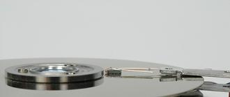
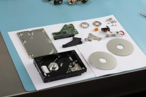
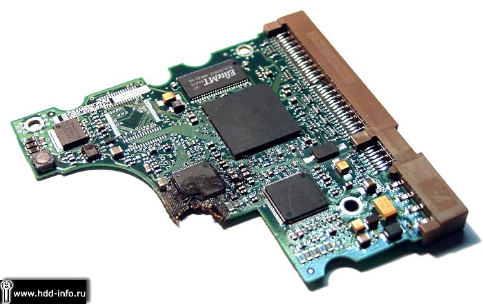
Diagnostics drive must begin with a visual inspection.
To do this, simply inspect the electronics board and try to find damage on it, which may include:
- Burned out items.
- Knocked down and chipped items.
If nothing abnormal on the electronics board is detected, then go to the second stage and connect the drive to the computer.
First you need to connect only power to the drive!
A normal drive should first unwind, then recalibrate, and then continue to rotate the spindle.
If the drive does not spin up, then several options are possible:
- damaged electronics board.
- block switch damaged magnetic heads.
- spindle shaft wedged.
- "stuck" heads.
Accurately understanding the reason is usually quite difficult, and most convenient way Diagnosis usually consists of a complete replacement of the electronics board. However, the electronics board must be compatible with the drive, and not only on the hardware, but also on the software level.
If the drive spins up, but starts knocking, then, as a rule, this indicates a malfunction inside the HDA and cannot be removed by itself. In rare cases, a malfunction of the electronics board is also possible.
If the disc is unwound, then it is necessary to evaluate it by software. For this it is very convenient to take the program MHDD. You can download it either on the website of the author, or on our website in the "Download" section. Works this program from MS-DOS, so it is distributed as a floppy image or ISO image CD from which you can boot. Before using the program, it is highly desirable to familiarize yourself with its documentation. To diagnose the hard disk is best to connect to the Secondary IDE port or any SATA, depending on the interface this drive. After downloading the program, select the channel to which the diagnosed drive is connected, and press F2. The program will attempt to read the drive's passport. If the passport of the drive was able to be counted, and it corresponds to what is indicated on the label hard drive, the problem is most likely not in the electronics board. The exception to this rule may be the "knocked-out" bits of the interface, which is manifested in the incorrect name of the drive or other "garbage" that appears when reading a passport. For example, the drive is not defined as Toshiba, but as To & hiba.
If everything is correct in the passport, you can try to scan the disk surface for the presence of bad blocks on it. This is done using the F4 key.
If there are no bad-blocks on the surface, or there are only a few of them, then the problem is definitely not in the electronics board, and you need to use means of recovering the logical problems of the drive like R-Studio or Easy Recovery. You can download these programs in the "Download" section of our website.
If the electronics board is damaged (i.e., the drive's passport could not be counted), then its repair or replacement is necessary. This repair is quite complicated and usually comes down to a complete replacement of the board. This question for each disk family is solved in its own way, so we consider the disks by families.
We consider the most common families of drives that are being produced at the moment, or those that have already been discontinued, but are the predecessors of current families.
Company stores Seagate.
Seagate drives are divided into two families:
- "Fish-like". (Modeled on Barracuda drives).
- U-series. (Patterned on U-Series Sigates).
For rough selection of the board on the Seagate “fish-like” series drives, it is necessary to match the version of the Firmware indicated on the label attached to the hot-block. In addition, the amount of cache should not be less than on the original board.
That is, on drives with a cache size of 2 megabytes, you can install boards with a buffer size of 8 megabytes, but not vice versa.
If a rough selection of the board failed, and the drive is still not detected and the BUSU indicator is active in the MHDD program, this means that the board most likely did not fit - the ROM version did not match the overlay version in the drive's service area.
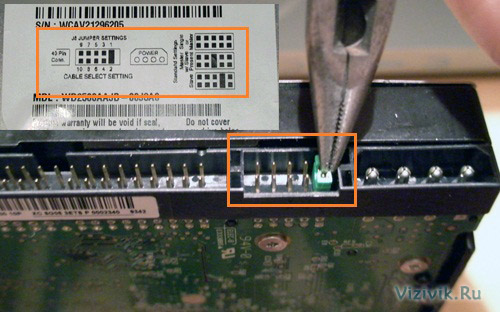
For a "fine" board selection, you need to find out what version of the ROM was in the motherboard. To do this, you need to make a special terminal adapter and connect it to the RS-232 diagnostic interface built into the drive. The adapter adapter is shown in the figure.
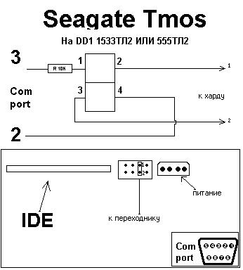
After connecting the drive through the adapter, you must run a terminal program, for example Hyperterminal or Putty at a speed of 9600 bps, and turn on the drive. A drive greeting will appear on the screen, and further diagnostics indicating the reason why the drive is not working. The approximate version of the diagnostics that is displayed on the screen is shown in the figure.

In this case, it is clear that the firmware version is M-14.
If the "native" board of the drive is damaged so much that it does not even issue greetings to the terminal, then you need to try to pick up a board with another version of the ROM than the one that has already been tried for installation. Different versions of the ROM, with the same version of the Firmware specified on the cover of the HDA, are characteristic of disks, starting with the Barracuda ATA V. The previous series for each version of the Firmware had one type of ROM. For Barracuda ATA V and older models, this problem It can be solved by simple soldering the ROM chip from the "dead" board to the "live" one. For families of drives, starting with Barracuda 7200.7, on some types of boards, a mask ROM is used that is inside the processor.
With drives Seagate U-series, everything is somewhat simpler. They are similar in this regard to drives Seagate Barracuda ATA 4 and below, i.e. it’s enough for them to choose an electronics board with the same version of Firmaware on the label. If the firmware version does not match, you can rewire the flash memory chip from one board to another.
Drives Maxtor.
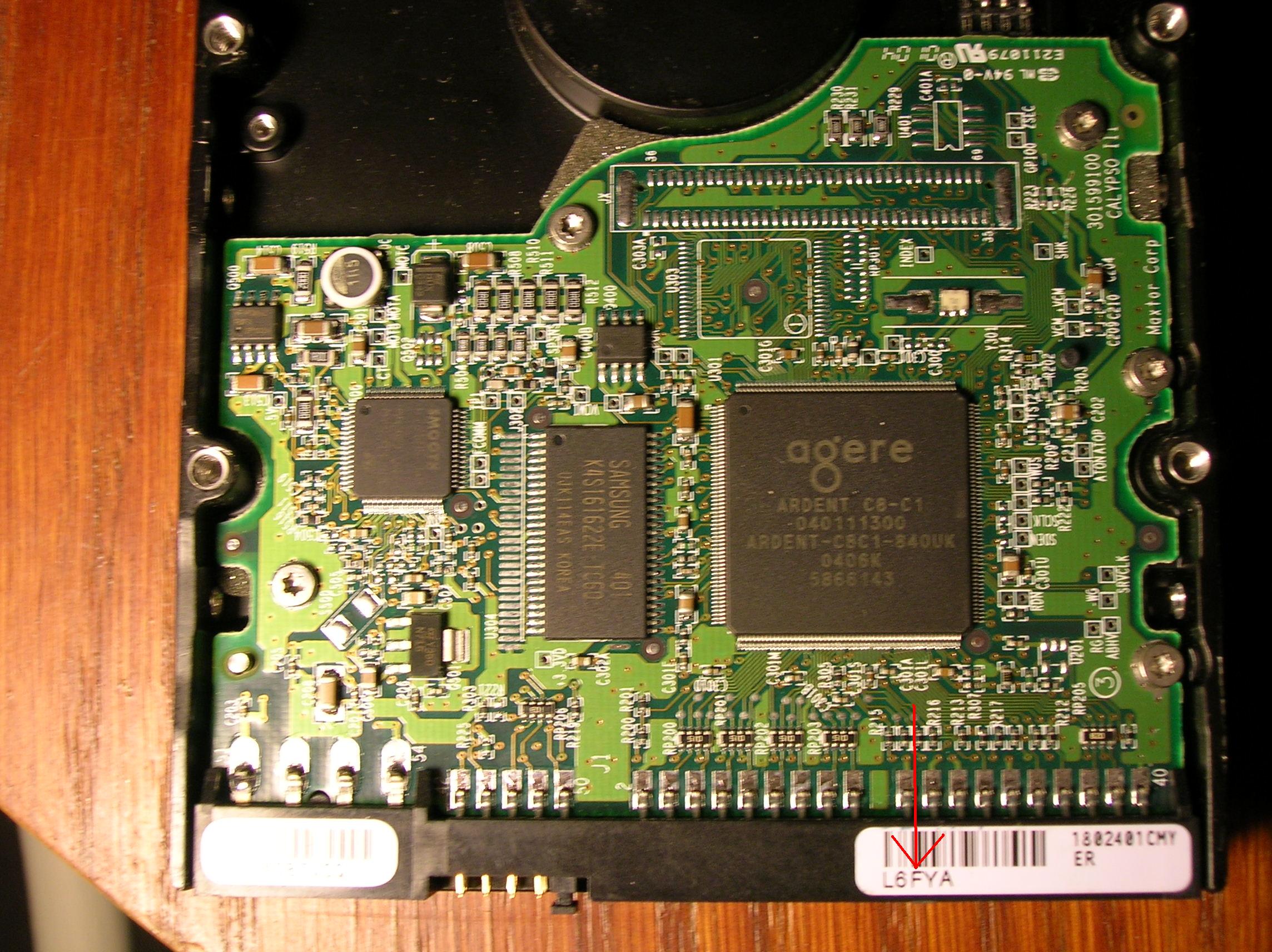
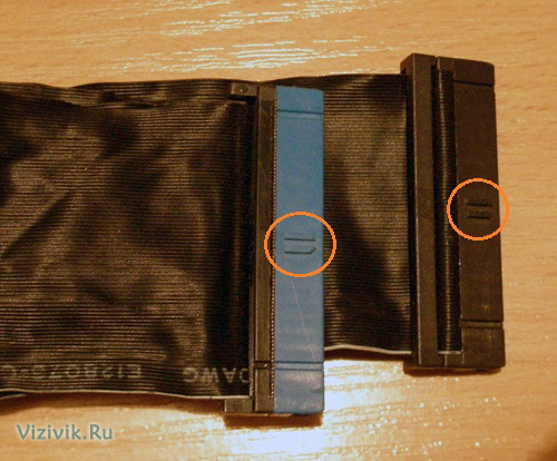
For Maxtor drives, control board malfunctions are quite common. Usually, the engine driver burns on the board. To replace the board, it is necessary to match the labels on the IDE connectors.
Drives Western digital .
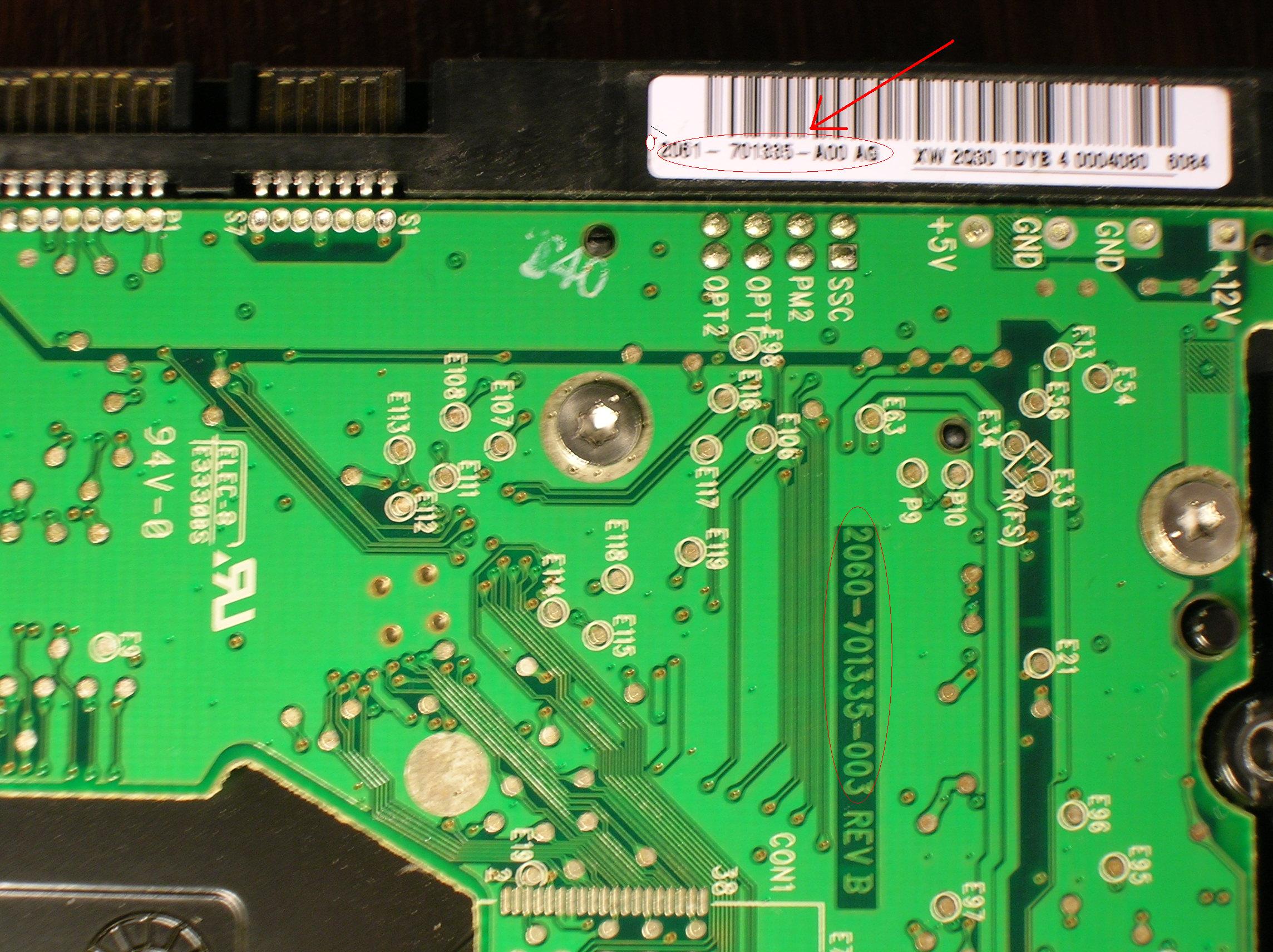
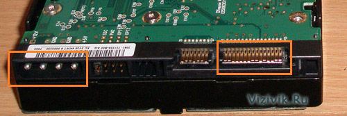
Western digital drives are characterized by a large number of different board versions. To select a suitable board, it is necessary that the boards have matching labels on the IDE connectors. Characters that must match are circled in red. However, besides this, it is necessary to match the ROM version and match additional parameters in ROM. Therefore, it is best to also solder the ROM when replacing the board. If there is no possibility to solder the ROM, then at least it is necessary to use a card from the same disk model. The MDL inscriptions on the cover of the HM unit (see figure) must coincide completely.
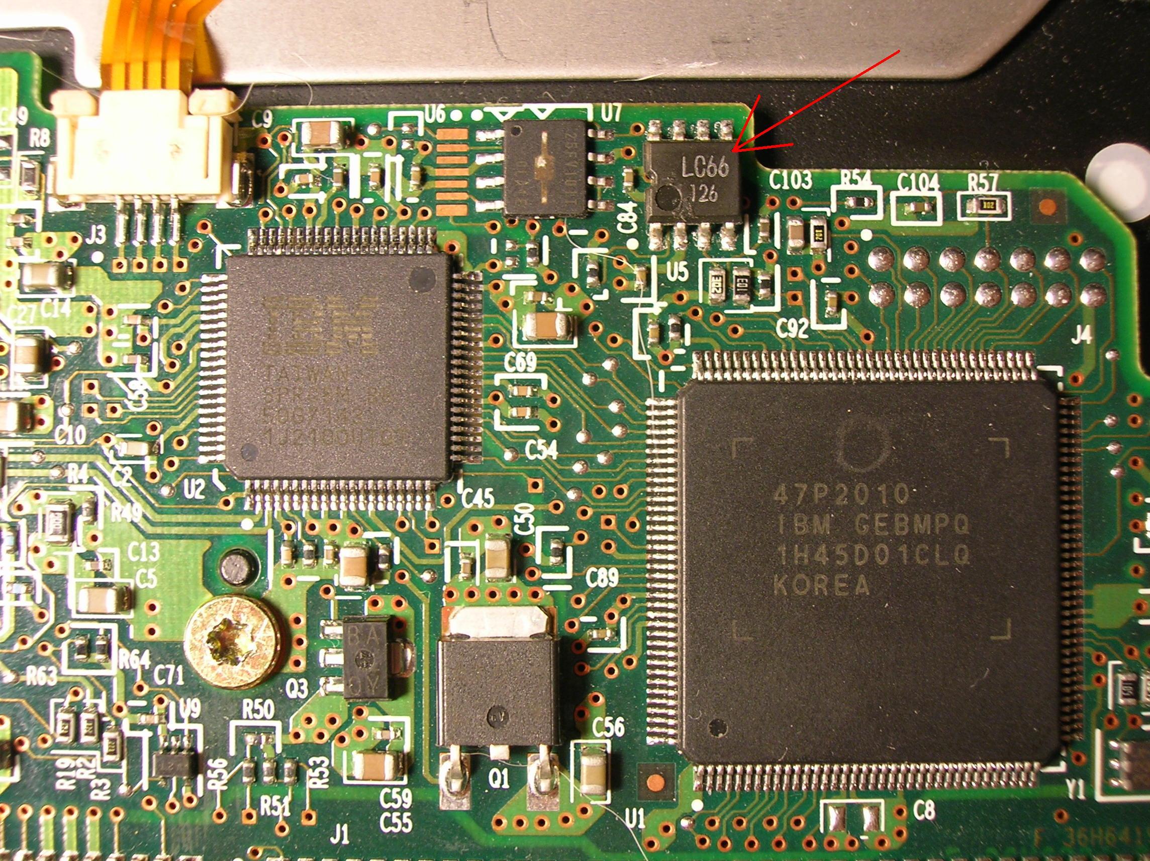
Drives IbmHitachi.
These drives on the board have a NVRAM non-volatile memory chip, which stores configuration parameters. For relatively old IBM drives, you can simply pick up a board with the same firmware version, but this is quite difficult and usually easier to solder the chip. In some cases, it is desirable to solder the ROM chip as well. The new drives in NVRAM also contain adaptive settings, so the chip will have to be re-soldered anyway. This should be done very carefully, because careless handling can lead to chip damage, and this will greatly complicate or make it completely impossible to recover information from the drive.
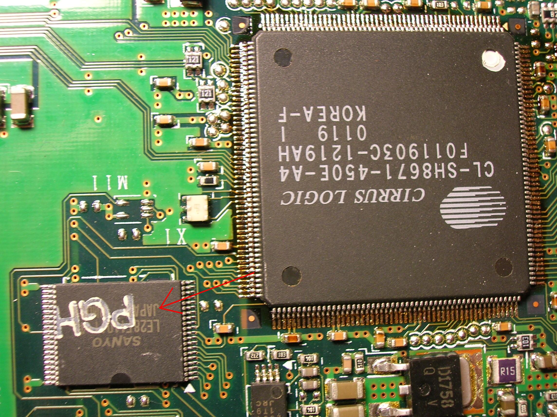
Drives Fujitsu.
These drives have many versions of the ROM. The ROM version is indicated on the cover. In addition to this, some instances of the MPG3XXXAT series of drives have adaptive settings in the ROM. In addition, ROM is a map of heads, which sometimes also matters. Therefore, it is better to re-read the ROM.

Of course, in this article it is impossible to highlight all the subtleties of repairing drives, and besides, in addition to knowledge, you also need to have some experience and skills to handle these "devices".
Therefore, if after reading the article and taking the measures described in it, your disk has not earned, then perhaps you should not continue to torment it and finally break it, but it makes sense to turn to experts?
Golovnyak Sergey.
Leading Specialist
Sergol group
In this article we will consider the installation of drives on hard drives. In particular, consider their configuration and physical installation.
In order to install in computer hard drive, you must do the following:
- configure the drive;
- configure the controller or interface device;
- install the drive in the computer case;
- configure the system as a whole for disk recognition;
- perform logical partitioning of the disk;
- perform high-level formatting of partitions or volumes.
Before proceeding with the installation of a hard disk, it is advisable to familiarize yourself with the documentation for this drive, controller or main adapter, system BIOS, and some other computer devices. But, as a rule, this will give nothing to a simple user, so the documentation can be put aside. In modern computer systems, it is optional.
If, after all, you decide to familiarize yourself with the documentation, the collecting company will provide you with only limited information about this device. As a rule, complete documentation should be searched and downloaded from the device manufacturer’s website. The same applies to other devices of most systems that are on the market today.
Hard drive configuration
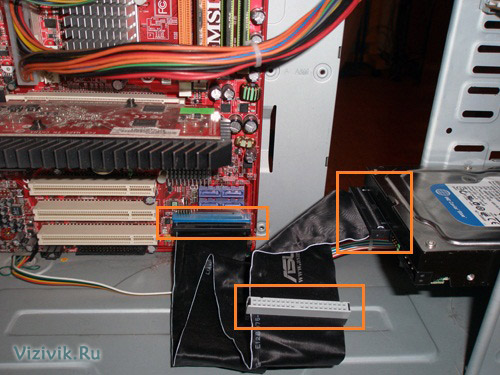
Before you proceed to the installation of a hard disk, it must be configured. IDE drives often require a master-slave switch, or you can also use the Cable Select option and an 80-core cable.
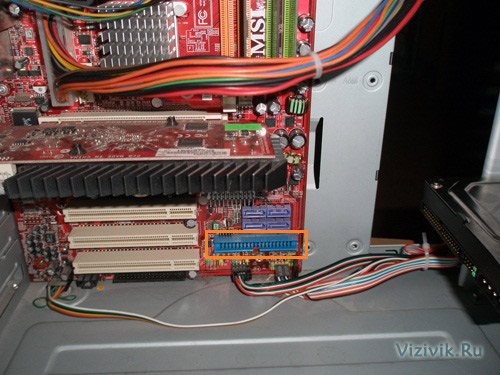
You do not need to install these jumpers to configure Serial ATA hard drives. There are cases that nevertheless drives have such jumpers installed directly at the factory.
SATA hard drives connect to the SATA controller using a cable, forming a point-to-point connection.

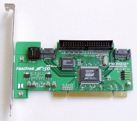
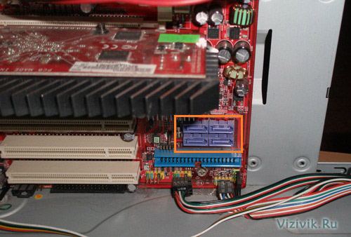
Unlike hard drives based on the parallel ATA interface (outdated version), SATA drives do not have any master or slave devices. The picture shows that some SATA drives have jumpers to allow compatibility. In modern hard drives with a data transfer rate of 300/150 Mbit / s to switch to a slower mode, which is necessary for the correct operation of the old controllers, you need to rearrange the jumper. For reasons of compatibility with drivers and other software most controllers can operate in a “compatibility mode”, in which the master-slave configuration is emulated, but this mode is not physically implemented.
Hard disk controller configuration
The hard disk controller in older models is installed in the slot motherboard. All recently developed IDE and SATA drives have an integrated controller on the motherboard. Almost always, the ATA device controller is integrated into the motherboard and configured using the BIOS setup utility. In this case, a separate controller does not exist. Some systems may have a controller on an expansion card in addition to an integrated controller. This situation can occur when the integrated controller does not support faster data exchange modes (300 Mbit / s for SATA and 133 Mbit / s for PATA) typical of new hard drives.
In such cases, you do not need to resort to installing the controller in the motherboard, it is better to upgrade the motherboard itself, so you will get additional functionality and spend a little more.
There are also cases when adding a controller card makes sense, for example, new drive SATA is "suspended" on an old motherboard, on which there is no this controller.
Controllers on expansion cards require a certain combination of the following system resources:
- boot ROM address (optional);
- interrupt (IRQ);
- direct memory access (DMA) channel;
- i / O port address
Not all controllers use each of these resources, but there are some. In most cases, modern controllers and systems supporting Plug Ang Play technology are automatically configured. basic system computer I / O and operating system. The system allocates such resources that do not lead to conflicts with other devices of the computer.
If the operating system or hardware does not support Plug and Play, then the adapter must be manually configured. Some controller cards come with utilities that allow you to program this configuration, while other controllers have a number of switches or jumpers.
The ATA interface driver is part of the standard system. Computer BIOS and allows booting from PATA and SATA devices. In such systems, which contain the SATA interface on the motherboard, the driver of this interface is also built into the BIOS. The BIOS provides the device functionality that the system needs to access the disk before it can download any file from it.
Notice!
Although the Windows operating system (OS) supports standard IDE / ATA drivers, this type of interface usually integrates into the components of the south bridge or the I / O controller chipset of the motherboard and requires the download of special drivers. When using a motherboard that is newer than your OS version (for example, a new motherboard purchased in 2010 that is operating windows environment XP), make sure that immediately after install windows the chipset drivers that came with the motherboard. If the controller supports SATA in the Advanced Host Controller Interface (ACHI) mode or a SATA RAID array (Redundant Array of Independent Disks is a redundant array of independent disks), and the computer is running Windows XP or earlier, it is usually necessary to install driver on floppy disk or pre-written to installation disk Windows
Keep in mind that all these drivers are included in the installation kit. Windows vista and 7. If the controller is older than the installed operating system, the necessary drivers will most likely be included on the installation CD. At the same time, it is always recommended to search the Internet for the latest version of the controller driver and install it immediately after the operating system.
There are SATA controllers that have their own BIOS that supports ACHI, RAID, large disks, or other functions. If you are not going to use these functions or the motherboard BIOS itself has this support, then it is not necessary to use the controller BIOS. Many controllers on expansion cards have switches, jumpers, or support programs that allow you to enable or disable BIOS support.
In addition to the features bIOS boot The controller provides other functions such as:
- configuring RAID
- controller configuration;
- diagnostics.
If the controller's BIOS is enabled, to place it you need an address space in the high memory area (UMA), which occupies the last 384 KB within the first megabyte system memory. The upper memory is divided into three sections with two segments each 64 KB in size, with the first section being allotted for the video adapter memory and the last one for the system BIOS. The C000h and D000h segments are reserved for BIOS adapters, in particular for hard disk controllers and graphics controllers.
Notice!
The memory areas occupied by the BIOS of various adapters should not overlap. Most boards have switches and jumpers with which you can change the BIOS addresses, sometimes it can be done programmatically, thereby preventing a possible conflict.
Installation of hard disk drives
Hard drives are mounted in the computer case. To do this, you need the appropriate screws, brackets, front panel, etc.
For the installation of some drives will require plastic guides that are attached to the device on both sides and allow you to install it in the appropriate place in the case.

These guides should be attached to the computer case or to the hard drive when purchased.
Since PATA and SATA devices use different types of cables, check if the cable matches the controller and the drive. To use PATA mode with a speed of 66 Mbps and faster (up to 133 Mbps), you will need an 80-wire cable. It is also recommended to use when more low speeds data transfer such as 33 Mbps or less. To determine which cable you have (40- or 80-wire), count the hillocks on the cable - each hillock corresponds to one core. One of the characteristic features of an 80-core cable is the color of its plugs: inserted into the motherboard is colored blue, and inserted into the master and slave devices is black and gray, respectively.
If you plan to install a 3.5-inch hard drive in a 5.25-inch frame, you will need a different type of mounting pad. Most 3.5-inch disks have such overlays in the kit.
They can also be included in the enclosure package.

Notice!
It is necessary to choose the length of the connecting cable (cable). In some cases, the cable does not reach the new hard drive. Try to move it to the nearest compartment, or use a longer cable. The length of the IDE drive cable is limited to 45 cm, the shorter the better. However, in the set of some cases you can find longer cables, up to 67cm, besides having 80 wires. Long cables, especially those with irregular, ‘‘ rounded ’’ length, are not recommended, especially for disks with a data transfer rate of 133 Mbps. Using too long cables causes transmission time errors and signal weakening; data may also be corrupted on disk. If you use a cable longer than 45 cm, then, as they say, you create problems for yourself.
After unpacking a new hard drive, you should have the following:
- the device itself;
- software (optional);
- mounting plates and screws.
Devices supplied as OEMs, i.e. in packages, except themselves may not have anything in the kit. In this case, you yourself will have to take care of the cables, screws and other accessories.
Mounting an ATA (PATA) hard drive
To mount an ATA hard drive, follow these steps:
1. See if there is an unused 40-core IDE connector in the computer. With a Pentium processor, you can install four IDE devices in your computer (two for each channel).
Tip!
To improve the performance of simultaneously used devices, such as drives and hard drives on optical discs, they are connected to various cables. Hard disk and drive is not recommended to "hang" on one cable.
2. Notice how the cable is connected to the drive. The red wire of the power cable is connected to the first pin of the drive connector. Although the plug has a special key for wrong connection to the hard drive, it can easily be incorrectly connected, which will lead to failure of the device.
The first contact of the cable is most often oriented closer to the power connector of the device. On the cable there is a special key for the correct connection to the device.
Tip!
Remember that modern ATA hard drives require an 80-wire cable for Ultra-DMA (66-133 Mbps) high-speed operation, and you can also use it to connect older devices. A 40-wire cable can be used to connect devices with a speed of 33 Mbps or less. The advantage of the 80-pin cable is that the devices will have to install only the CS (Cable Select) jumper, and you do not need to choose which device will be the master and which the slave. Today, ATA-connection is already quite rare, all modern hard drives connect via SATA interface.
3. Set the Master / Slave / Cable Select switches on the back of the hard drive. When using an 80-pin cable, it is enough to install the Cable Select jumper on all devices. Otherwise, one of the devices connected to the loop must be master (master) and the other slave (slave). Please note that some outdated devices, when used as a leader in a pair with another slave, require simultaneous installation of Master and Slave jumpers. But today, it is unlikely you will come across such hard drives in your hands.
4. Place the drive in the 3.5-inch chassis compartment and fasten it with screws. When performing this operation, it is impossible to exert considerable mechanical effort - the drive must freely fall into its place in the housing.
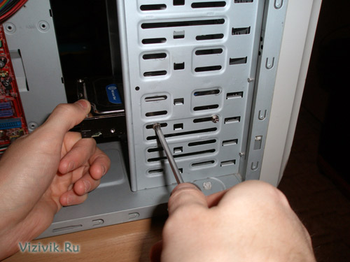
Make sure the screws are not too long. If the screw is longer than the depth of the hole into which it will be screwed, you can damage the device and disrupt the thread.
5. Attach the interface cable to the back of the drive. If an 80-pin cable is used, the blue plug must be plugged into the motherboard slot, the black plug into the master device slot, and the gray plug (usually the middle one) into the slave socket.

6. Connect the power cable to the hard drive, most often it is four-core with a standard connector.
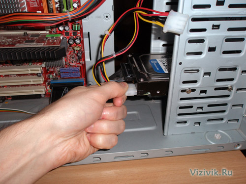
This completes the installation of the ATA hard drive.
Will consider connecting hard SATA drives.
Mounting SATA Hard Drives
Step-by-step installation procedure hard sATA drive somewhat different from installing ATA drives.
1. Check if there are unused SATA connectors in the system.
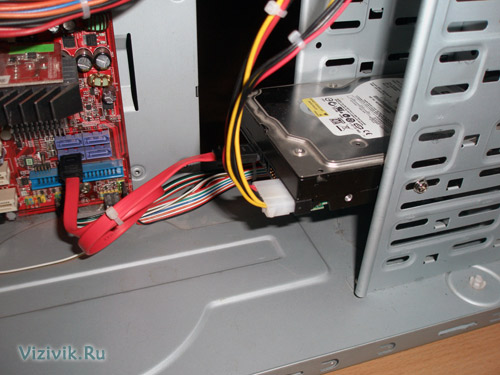
2. Gently insert the hard drive into the bay of the appropriate size, using pads if necessary, and tighten the fastening screws.
3. Connect the SATA data cable to the SATA controller. Data cables can be combined in a single sheath with a SATA power cable. When using a separate data cable, one connector is connected to the drive and the other to the SATA controller.

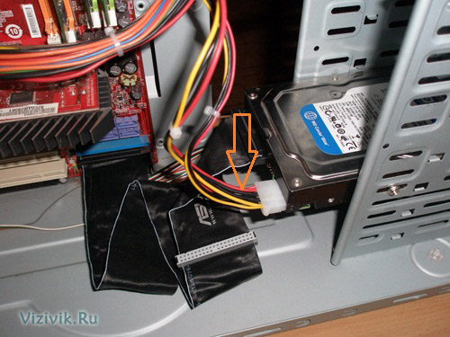
4. Connect the appropriate power cable to the drive. Some SATA devices have two power connectors: standard 4-pin and special 15-pin - in this case, apply power to any of them (but not two at the same time). If the device has only a 15-pin power connection, and the power supply does not offer such a plug, you will have to additionally purchase a special adapter “4 to 15” (if it is not included in the device kit).
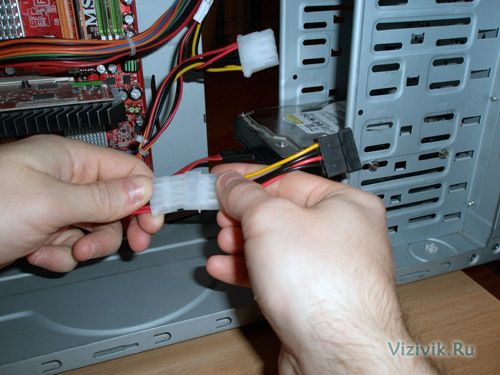
Power connection through a special adapter "4 to 15"
Attention!If the device has 2 power sockets at the same time (standard, 4-pin, and SATA-type, 15-pin), in no case do not apply power to both connectors at the same time, otherwise you may damage the device.
system configuration
After the hard disk is mounted in the computer case, you can begin to configure the system. The computer needs to provide information about the drive so that it can be loaded at power on.
On Windows 2000, XP, Vista and 7, the command is used. They can be found on the boot CD of the operating system. If an operating system is installed on a new disk, its division and formatting will be performed as part of the overall OS installation process.
If you want, you can create partitions and perform formatting manually before installing the operating system, but this will have to use special programs. It is easier to do this during the installation of the system and its means.
Automatically detect the type of hard disk
Almost all PATA and SATA drives in modern BIOS provide automatic type detection, i.e. from the drive on request, the system reads its characteristics and the necessary parameters. With this approach, errors that can be made when entering parameters manually are practically excluded.
And so, let's get started.
1. Turn on the computer and press the key required to enter bIOS settingsas a rule, it is Delete or F1. If the BIOS provides for automatic detection of devices, it is recommended to set this mode, since the optimal parameters of the device will be determined. SATA devices may also have support for ACHI mode and grouping multiple devices into a RAID array. Set the ACHI option for SATA drives, if supported, and exit the BIOS setup program.
2. Reboot the system. If a installed device is not bootable, and you are running Windows XP or a later version of this OS, the new drive will be automatically detected during the boot process, and the necessary drivers will be installed for it. It should be noted that the system will not see the new device as a volume (that is, it will not be assigned a letter) until the disk partitions are created and their formatting is performed.
If the new device is bootable, you will have to boot from the CD again to create partitions on the new disk, perform formatting, and install an operating system on it. If a motherboard supports SATA in ACHI mode or SATA RAID arrays and you are running Windows XP or an earlier version of this OS, to install the device you will have to use a controller driver diskette or rewrite these drivers to the installation windows disk or use a floppy disk drive. Otherwise, the system does not recognize the hard disk and the installation process will not be possible.
I note that all the necessary drivers are already integrated into the new operating systems Windows Vista and 7, and during their installation, problems with determining hard controller the disk does not arise.
Manually determine the type of drive
If your computer has a motherboard that does not support automatic detection, you will have to enter the appropriate information in the BIOS manually. Several standard combinations are available in the BIOS, however, they are most likely outdated, as they provide support for drives of only a few hundred megabytes, or even less. Most often you will have to select a custom hard disk type, and then specify the values of the following parameters:
- number of cylinders;
- number of heads;
- number of sectors per track.
The required parameter values can be found in the documentation that came with the hard disk, but they can be printed on a sticker on the hard disk case. Be sure to remember or write them down.
The latter option is preferable, since you will need the parameter values if the system BIOS suddenly “forgets” them due to a dead battery on the motherboard. Recorded information is best stored directly inside. system unitfor example, they can be glued to the body with adhesive tape. Sometimes it saves a lot of time.
In the event that you are unable to determine the correct values of the parameters of your hard disk, refer to the website of the manufacturer. You can also use one of the diagnostic tools available for download via the Internet.
Depending on the BIOS manufacturer and its version, you are given the opportunity to configure other parameters of the hard disk, in particular, the data transfer mode and logical unit addressing.
Still, if the BIOS of your motherboard does not support the automatic detection function, then you need to think about upgrading your computer and replacing the outdated motherboard with a more modern one, which includes many different functions, including support for modern hard disk drives.
This type includes faults associated with physical damage to the components of the disk controller: burned-out chips, damaged heads, detached interface cable, etc.
There are two options for determining such faults.
The first one is the simplest, when signs of destruction of the controller components, for example, holes on the microcircuits, are detected during external examination. In this case, before starting any action, replace the burned components.
The second option, respectively, is the most difficult: when there are no visible signs of damage, however, the hard disk behaves non-standard. Consider some situations.
- Engine not spinning, no sound is heard . Possible reasons - the spindle motor or read / write heads stuck to the disk surface.
If you try to turn the spindle, it can lead not only to damage the surface of the disk and, accordingly, to the loss of information, but also to a breakdown of the control mechanism of the heads and the heads themselves. In this case, the faulty hard drive is best attributed to service centerwhere, firstly, they will tell you exactly whether the hard disk is subject to repair, and secondly, they will overwrite all important information from it
- The engine spins up, a click is heard . This click is the result of unsuccessful unparking of heads. The most likely cause of this failure is the failure of the spindle motor generator or the head positioning system. It is also possible damage to the positioning coil, which is located on the head unit.
- The engine spins , but the disk is not detected or incorrectly determined . The cause of such a malfunction may be the failure of the controller interface chip or mechanical damage to the contact group to which the data loop is connected (for example, a bent or broken metal pin).
The disc is spinning, heard knock . This situation can mean a lot, starting with a faulty positioning system and ending with damage to the heads. Another option - bad sectors in the boot area of the hard drive. This situation you can fix yourself. Defining hard condition disk, connect the loop data. Now you can not only hear the published hard drive sounds, but also to see on the screen error messages during the hard drive. The following main situations are possible.
The appearance of messages like Invalid Drive Specification. Such messages mean that the BIOS contains incorrect information about the parameters of the installed hard drive, or it is incorrectly recognized. The last option says about the destruction of service information or damage to the heads. It is also possible that the interface contacts are broken on the controller board or in the data loop itself.
The appearance of messages like Disk boot failure. This clearly indicates that the MBR (Master Boot Record) is damaged - the master boot record.
The appearance of messages like Boot disk failed. The most likely reason is the presence of bad sectors on the zero track, so that booting from the hard disk is impossible. OSs normally recognize the hard disk, however does not display logical discs. If we exclude the option that the hard drive is simply not broken into logical drives, the main cause of this failure is the presence of failed disks in the system area or destruction file systemcontaining information about the current disk configuration. In this case, you should re-split the hard drive into logical disks, and then format it. You can also examine the problem in more detail using low-level utilities.
The hard disk is recognized normally, however OS is not fully loaded or does not load at all. This fact indicates that the hard drive area in which the files of the operating system are written contains bad sectors. In this case, refer to the low-level utilities, which will mark bad sectors and, if necessary, reschedule the hard drive.
HDD Prevention
Over time, the disc begins to work more slowly, malfunctioning, heats up, reading errors appear, etc. This means that the time has come for prevention, the main measures of which are:
- Check the logical and physical state disk using diagnostic tools type scandisk (for windows systems 95/98) . Such a check allows not only to correct logical errors, freeing up space on the hard disk, but also to learn about the appearance of bad sectors, which the utility marks accordingly. Windows XP checks the disk a little differently, but the verification mechanism is the same: to launch the utility, right-click on the disk of interest to you, select Properties Service Checkout... In the window that opens, set the required scan parameters and run the diagnostics for execution.
In Windows-7: “Start” “All Programs” “Standard” “Utility” “Disk Cleanup” or download and install TreeSize Free.
- Defragment files using standard utilities or third-party utilities. Fragmentation is the breaking up of a single file into several fragments and placing them on different parts of a disk. Fragmentation does not occur deliberately, but because of the specifics of recording information. Defragmentation - respectively, the connection of fragments of a single file. If the disk is defragmented, the speed of access to information increases. Over time, the fragmentation of new files again leads to slower work, in this case, the defragmentation process should be repeated.
- Disk temperature monitoring using specialized utilities. Temperature affects your hard disk performance like nothing else. As a result of the increase in temperature, the internal components of the controller may suffer, causing serious malfunctions. This is quite enough to ensure at least the logical "health" of the hard disk.
Practical part
EXERCISE 1. Replace the hard drive and install the operating system.
Problems with the controller in hard drives occur quite often. They may be due to a PC power failure, overheating, moisture ingress, or for no apparent reason. The defect of the board can be visible (for example, due to mechanical damage or burnout of the elements) or invisible (the board is usually screwed up so that all its elements are hidden by the disc case).
Symptoms
Most often there are no sounds, the engine does not rotate, the disk is not detected. The elements of the board may become excessively hot, and a short circuit on the disk will prevent the computer itself from turning on. Of unusual cases - the engine spins up, after which there will be a rhythmic knock. This is a symptom of broken heads, and sometimes the result of their lack of proper control, for which the board element is responsible.
Related problems
Since the disk with the faulty card is “immobilized”, this problem is an obstacle to the identification of many other diagnoses. The most frequent unpleasant addition is the malfunctioning of the magnetic heads unit, since the internal electronics may suffer as a result of power problems.
Cheating problems
Malfunction board is easily confused with other problems. If you do not hear the rotation of the disc, you can incorrectly diagnose the disc with a jammed motor. However, if you have already found out that the disk is faulty, it is important not to connect it to the power supply, since in this case the probability of failure of the entire electronics of the disk, and at the same time the engine, is high.
And one more interesting feature of the diagnosis
The “Controller” diagnosis can be made not because the board itself is faulty, but because in order to solve other disk problems, exactly the same manipulations are needed as with its malfunction. For example, it concerns. It's all about their “on-board”, that is, the USB interface soldered to the board itself. It does not allow sending ATA-commands to a disk and working in special technological modes, and therefore we can use all the advantages of the PC3000Express software and hardware complex only by circumventing an unsuitable USB interface. Therefore, for external WD 2.5 ′ drives, any diagnoses of hardware malfunctions are supplemented with a “controller” diagnosis, even if it is healthy.
The most common phrase that is heard from users who have problems with the hard disk: "Change my controller on the hard disk, I will copy the data myself." Yes, there are cases of HDD controller failure. The main reasons for its failure are electrical and mechanical stress.
Immediately we must make a reservation that on modern hard drives a simple rearrangement of the electronics board will do nothing. Even if hard are very similar in model and volume.
The hard disk controller contains firmware that is connected to a counter hard disk. The discrepancy between the firmware of the electronics board and the hard disk microcode will not allow it to be determined by the operating system. For a proper replacement of the controller, it is necessary that, in addition to the firmware, the markings of the central processor and all the chips on the hard disk electronics board should completely coincide.
When replacing the controller on the hard disk is not required
When power is applied, the hard disk is unwound, detected by the computer, but data is not available. The controller has nothing to do with it. Most likely the whole thing in a large number of other sectors (usually at the beginning of the hard drive), which interfere with the work of the HDD.
Bad areas may be in the service area of the hard disk. This may also be the reason that the drive does not go to readiness.
Characteristic example of a Seagate Barracuda 7200.11 hard drive. The well-known problem of the 7200.11 series is a violation of the drive firmware. However, more than half of the users who contacted us persistently asked to change the controller on the hard disk.
Another case. The hard disk is spun, not detected by the computer. An extraneous mechanical knock is heard. Here the controller is also not to blame. The problem with the unit magnetic heads.
Mechanical damage to the hard disk controller
The most common failure is damage to the electronics board connector. When inaccurately connecting cables or applying large efforts by the user, the socket of the connector breaks. After replacing the smart connector, we get a working hard drive.
But there are nuances. If the user tries to start the hard disk by applying power, begins to move (press) the power connector or interface cable. The consequence of such actions can be a variety of problems. And electrical damage to the elements on the controller board, and sticking of a block of magnetic heads on the magnetic surface of the hard disk due to the unstable operation of the drive.
Sometimes, if the hard drive is not carefully installed or removed from the computer, individual elements of the board break off (on those models of controllers where the elements are on the outer side of the board). In this case, after repairing the controller, we also get a working drive. If the user did not notice the breakdown and turned on the hard drive, then in this case there could be electrical damage to both the board and the switch on the head unit.
When the need to replace the controller on the hard disk
 Serious mechanical damage to the HDD controller that does not allow repairing it to restore functionality. In this case, yes, you need to select the correct controller for the replacement and rewire or reflash the firmware from the broken board.
The hard disk blocks the start of the computer. Either the hard disk does not show any signs of life during power up. This is due to the electrical breakdown of the controller.
If the damage is serious and it cannot be repaired, replacing the burned parts is impossible, then the controller should be replaced.