Currently, the most common are two standards for connecting a hard drive to a computer. The first, the most common among home and office PCs - IDE (Integrated Device Electronics - device with a built-in controller), also referred to as ATA (AT Attachment - connected to the AT). The second is most often found in servers and high-performance workstations - SCSI (Small Computer System Interface, pronounced as \\\\\\ "skazi \\\\\\"). It should be noted that this interface is not specialized for disk devices. Addition hard disks and CD-ROM drives, there is a huge mass of devices working on this standard.
The goal was that the disks could simply be installed and removed without changing the jumpers, without the possibility of conflict due to wrong settings crosspieces. With such a cable, the drive attached to the middle connector is slave; The drive attached to the connector farthest from the interface is the master. If only one drive is installed on this cable, this leaves a long "plug" of the cable hanging loose, nothing related to it. It is not possible to identify such cables visually, although you can check the type with a digital voltmeter or continuity tester between the two end connectors on the pin.
- Terminal 28 is not connected between the interface and the second drive position.
- Although this is a good idea in theory, in practice it rarely works.
The IDE interface standard was developed for some reasons. The most significant are:
An easier way to connect the hard drive to the computer bus. An IDE hard drive can be connected to the high-performance system bus of the computer and a slow LPT port with equal ease. Of course, in the latter case, the data exchange will be much lower, but there is such an opportunity.
Select this jumper position if this is the only device connected to the interface, or if this is the first of the two devices connected to the interface. Select this jumper position if it is the second device connected to the interface to which the host device is already connected.
Such devices may have an additional jumper position with the words "Single" or "Only". For such a device, drag it as the master if it is the only device on the interface or the slave device, if it is the second of the two devices on the interface.
Increase in speed. The disk controller is located directly on the device, which allows you to pass bypassing long interface wires.
You can connect an IDE device to a computer in several ways. The most common is a connection using a 40-wire cable (type of AT-BUS interface). The interface is 16-bit. The second type is the PC Card ATA - using the PC Card (PCMCIA), which also has a 16-bit interface. This type is used mainly in laptop computers. There are also XT IDE and MCA IDE, but we will not consider them here, since XT is already old enough to meet it very rarely, and MCA is used only for PS / 2 machines, which in our country practically do not occur.
The concept of computer hard disk interface
If it is a master on a channel that also has a slave device, connect both the master and slave jumpers. After you have connected your disks to the correct connectors on the cables and installed jumpers, it's time for the system to detect the disks. Reboot and you can use your disks. If you can not get your disks to work with the current configuration, try other settings as described. This will be useful if you determine on which interface you should connect your drive to make it the primary one.
In addition to the connection, the types of ATA interface are also different in terms of data transfer speed. Basic - CAM ATA (Common Access Method) - the standard defined by ANSI. Provides compatibility of IDE-devices at the level of signals and commands. Also allows you to connect up to two devices per cable. The length of the cable is not more than 46cm.
ATA-2 is an extension of the ATA specification. It has two channels, which allows you to connect up to 4 devices, support for disks up to 8GB. Supports the modes of operation PIO Mode 3, DMA Mode 1, Block mode. About these terms, we'll talk just below.
Simplified Cables and Connectors
This increased length enhances ease of use and flexibility when installing discs, especially in towers.
Operating System Compatibility
Most of them do not support hot-plugging. This helps to work in three ways.Command line support
Tips from Francisco Garcia Maseda. This is similar to an elevator that goes to each floor in the order in which the call buttons are pressed, ignoring people waiting for intermediate floors. This process, also called elevator lift, allows the drive to service read and write requests while minimizing head movement, which leads to increased productivity.
The next extension is Fast ATA-2. It differs only in support of DMA Mode 2, which allows you to achieve data transfer rates up to 13.3 MB / s and the presence of PIO Mode 4. This type is most often found in computer models based on 486-x and Pentium processors.
ATA-3. This expansion is more aimed at increasing reliability. Includes an improved power management tool and SMART technology (Self Monitoring Analysis and Report Technology - technology tracking, analysis and warning).
You simply connect the data cable to the drive and interface, connect the power cable to the drive and start using the drive. Data is written to the first disk until it is full, and then to the second disk until it is full, and so on.
Termination
In such an arrangement, called disk duplex, the array can continue to work after a single disk failure, a single host adapter, or both. Data is written to blocks in interleaved disks, with parity blocks alternating. Subsequent data blocks and parity blocks are written to three disks in such a way that data blocks and parity blocks are distributed equally on all three disks. The parity blocks are calculated in such a way that if either of the two data blocks is lost, it can be recovered using the parity block and the remaining data block.
Ultra DMA / 33 - the data transfer rate on the bus is 33 MB / sec. In addition, the control of the transmitted data is added. Relatively recently appeared the standard UDMA / 66, in which the speed was increased to 66 MB / sec, and only recently announced UDMA / 100.
It should be noted that these figures are only the maximum possible values. Actually, the data transfer speed can be significantly lower. It depends on the speed of the drives, the speed of the electronics, the memory and the processor.
This is absolutely wonderful information, it is always useful to remind the information that is taken for granted after the experience in the class. As shown in the diagram above, all three names of this popular interface hard drive have certain meanings that refer to the technology used.
To connect hard drives, this interface uses a 16-bit parallel connection. Inside the hollow interior of the box are several contacts arranged in two rows. This long port contains a cable that will connect the drive to the motherboard. Next to it is a power port containing four large contacts for connecting the cable to the computer.
In addition to the above types, there is also an ATAPI extension (ATA Package Interface). This extension is designed to connect to the ATA interface drives CD-ROM, CDRW, tape drives (tape drives), ZIP drives and other devices.
All of the above standards are electrically compatible.
Now let's talk a little about those terms that are used to describe the modes of operation of the hard drive. PIO (Programmed Input / Output) - when working in this mode, the process of information exchange with the hard disk buffer is handled by the CPU of the system. This, accordingly, takes away some part of the CPU time. There are six PIO modes that differ in data transfer speed. With PIO Mode 0, the speed is only 3.3 MB / s. And in the case of PIO Mode 5 already 20 MB / sec. Modes 0 to 2 refer to conventional ATA, 3 and 4 to ATA-2, and 5 to ATA-3.
Data transfer speed
It contains fewer contacts, which leads to fewer problems with electromagnetic interference. Its cable port is box-shaped, sometimes with three sides and without an upper side. Inside the box there is a small number of metal contacts.
These peripherals can be internal or external, including hard disks, and special enclosures containing several additional drives. They are commonly used in industry and server rooms of large companies. They are also louder and give more heat, which in turn requires more extensive cooling systems.
DMA (Direct Memory Access - direct memory access). When working in this mode, data exchange between the hard drive buffer and computer memory is performed directly by the hard disk controller. The DMA modes are divided into single word and multi word, depending on the number of words transmitted per bus operation. In the case of single-word mode, the maximum exchange rate is up to 8.3 MB / sec. When using verbose mode - up to 20 MB / sec. Appeals are made in pauses between CPU calls to memory. This mode saves CPU time, but somewhat reduces the rate of exchange.
This backward compatibility allows you to gradually update the old system components, while still retaining some of the benefits of the new technology. Connectors with 50 contacts still have a box-like structure containing two parallel rows of contacts. However, as the number of contacts increases, the connector slightly changes its shape, including inclined sides, rather than straight lines.
When you come to the sellers with questions about the hard drive, make sure that you are comfortable with them. A hard disk is a key component on any desktop computer. Because its reliability, storage capacity and interface functions directly affect the user's work, users should take care to examine the types of interfaces before making a choice. With a little research and careful consideration of the daily tasks that the computer must perform, users should be able to choose hDD with the type of interface that will be ideal for their needs.
When using a single-tasking operating system, for example MS-DOS, PIO mode is more preferable, in the case of multitasking systems it is better to use DMA mode. But in this case the support of this mode should be implemented at the level of drivers and special controllers.
LBA (Logical Block Addressing) - addressing of logical blocks. The ATA standard addresses the sector according to the classical scheme - the number of the cylinder, head and sector. However, due to historical reasons, Computer BIOS and operating system DOS limited the number of sectors (63) and cylinders (1024). As a result, there was a limit on the amount of hard disk in 540MB. In LBA mode, the address is transmitted as a linear absolute sector number. Winchester in this case, he himself converts it into the desired number of cylinders, heads and sectors. This allowed you to bypass the limitations on the amount of hard disk, but for DOS it still is 8GB. Operation of the device is possible only if this mode is supported by the driver (BIOS) and the device itself.
The ease of choice, coupled with increased productivity and lower cost of hard drives, led users to consume more terabytes than ever before. The storage volume became less dangerous, but there was one problem; The mechanical storage devices continued to serve as a bottleneck for overall system performance.
Today, to eliminate this bottleneck, a new generation of storage solutions is available, and this guide will help explain what's in the world of modern storage. The answer lies in the subsequent changes. Bandwidth rises, and the good news for consumers is that the physical connector has not changed.
There is also a Large mode - this mode is used Award BIOS to work with hard drives up to 1GB, not supporting LBA mode. Use this mode with disks over 1GB is not recommended.
Block Mode - block exchange mode. When using the normal mode, the hard drive receives a command to read the sector, puts it in its buffer, from which it moves to memory and waits for the command to read the next one. In the case of a block exchange, the hard drive first gets the number of reads by the sector, after which it reads them into the buffer, from where they are moved to the memory. Different models Winchesters have different buffer sizes, and accordingly can read a different number of sectors at a time. The maximum gain from working in this mode is possible only if the main work comes with data volumes no less than the number of sectors read. In the event that the data fragments are minimal (for example, no more than one sector), the use of this mode fades into nothing.
The mechanical device has rotating plates, from which the data is read and written magnetically. Consequently, the higher the rotation speed, the faster the disk, generally speaking. However, the raw speed is not the strong point of the hard drive, but what makes these storage solutions so attractive is the continuous improvement in the density of the areas, which provides greater bandwidth in the same form factor.
- Moving parts are subject to destruction.
- Limited resistance to shocks.
- Operation is limited to moving parts.
- Moving parts generate heat.
Finally, a few words about how to connect the IDE device. One IDE cable can connect up to two devices. One of the devices must be set to Master (master), and the second - to Slave (slave). Setting modes is carried out by setting jumper settings on the devices themselves. All modern IDE devices, as a rule, have a jumper setting table. If you have two hard drives, then the system will be loaded only from the Master device. Usually, the device is not allowed to operate in slave mode if there is no master device. However, modern drives and BIOS allow such work.
Cables and connectors
- High performance - significantly faster than the average hard disk.
- Without noise.
- Usually lower power consumption.
There is another mode - Cable Select. In this case, the definition of the master and slave device is made automatically based on the order of the connected connectors. To use this mode, you need a special cable and both devices must be installed in the CS.
I hope that this article was useful for you. In the next article, we will dwell in more detail on the SCSI standard and its modifications.
Hard Drive Interfaces
Advantages of performance only apply to cached data Generates noise when overclocking mechanical plates. Costs are twice as high as a hard disk with the same capacity. Limited impact resistance. One of the most expensive storage solutions. . However, now it is necessary to discuss the different types of hard drive interfaces that computer forensics will face. Therefore, to work with these devices, you may need older systems in your lab, and you also need to think about the appropriate drivers that will need to be installed.
In this article we will talk about what allows you to connect a hard drive to a computer, namely, the interface of the hard drive. More precisely, to talk about the interfaces of hard drives, because the technology to connect these devices for all of their existence was invented a great many, and the abundance of standards in this area can confuse inexperienced users. However, everything in order.
The disk controller is built into the drive itself. The disk controller facilitates communication between the computer's central processing unit and hard disks. As a rule, it is designed to prevent the possibility of turning it over. To create a connector with a key, the manufacturer usually removes pin 20 from the connector and locks pin 20 on the female cable connector, preventing the user from installing the cable back. Some cables also have a projection on the top of the female cable connector that is inserted into the recess in the casing surrounding the connector on the device.
Interfaces of hard disks (or strictly speaking, interfaces external storage devices, since they can act not only in their quality, but also other types of drives, for example, optical disc drives) are designed to exchange information between these devices external memory and motherboard. The interfaces of hard disks, not to a lesser extent than the physical parameters of the drives, affect many drive performance and performance. In particular, drive interfaces define such parameters as the data transfer speed between hard drive and the motherboard, the number of devices that can be connected to a computer, the ability to create disk arrays, the ability to hot-plug, support for NCQ and AHCI technologies, and so on. It also depends on the hard disk interface which cable, cord or adapter you need to connect to the motherboard.
It is recommended to use connectors and cables with keys. On this connector, pin 41 provides 5 V supply for the drive logic, pin 42 provides 5 V for the motor, and pin 43 provides power. The last contact is reserved and not used. Many manufacturers of inexpensive boards and cable networks do not use the keyboard. If they do not use a hidden connector with a recess and a corresponding protrusion on the cable connector, no manipulation exists, and the cables can be inserted back.
Tests can be different
Fortunately, the only consequence of this in most cases is that the device will not work until the cable is attached with the correct orientation. In rare situations, when you mix and match items, you may encounter a cable with a pin 20 lock and boards with pin 20 that are still present. In this case, you can break pin 20 from the board - or for more squeamish, remove the unit from the cable or replace the cable with one without a locked pin. In some cables, the unit is permanently installed as part of the connector housing, in which case you must disconnect the pin 20 on the card or the end of the device or use a different cable.
SCSI - Small Computer System Interface
The SCSI interface is one of the oldest interfaces designed to connect drives to personal computers. This standard appeared in the early 1980s. One of his developers was Alan Shugart, also known as the inventor of disk drives for floppy disks.
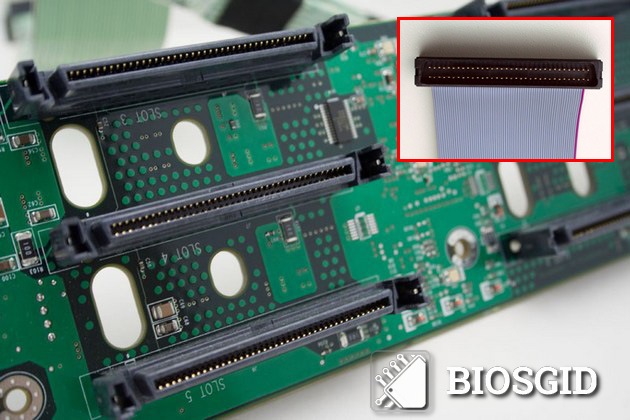
The appearance of the SCSI interface on the board and the connection cable to it
The SCSI standard (traditionally this abbreviation is read in Russian transcription as "skazi") was originally intended for use in personal computers, as evidenced by even the name of the format - Small Computer System Interface, or the system interface for small computers. However, it so happened that the drives of this type were used mainly in personal computers of the top class, and later in servers. It was due to the fact that, despite the successful architecture and a wide range of commands, the technical implementation of the interface was rather complicated, and did not fit the cost for a mass PC.
However, this standard has a number of features that are not available for other types of interfaces. For example, the Small Computer System Interface cable can have a maximum length of 12 m, and a transfer rate of 640 MB / s.
As with the IDE interface that appeared somewhat later, the SCSI interface is parallel. This means that the interface uses buses that transmit information over several conductors. This feature was one of the limiting factors for the development of the standard, and therefore, as a replacement, a more advanced, consistent standard SAS (from Serial Attached SCSI) was developed.
SAS - Serial Attached SCSI
![]()
This is the SAS interface of the server disk
Serial Attached SCSI was designed to improve the old enough interface for connecting hard drives to the Small Computers System Interface. Despite the fact that Serial Attached SCSI uses the main advantages of its predecessor, nevertheless, it has many advantages. Among them is worth noting the following:
- Using a shared bus by all devices.
- The serial data transfer protocol used by the SAS allows the use of fewer signal lines.
- There is no need for termination of the bus.
- Practically unlimited number of connected devices.
- Higher bandwidth (up to 12 Gb / s). In future implementations of the SAS protocol, it is planned to maintain a data rate of up to 24 Gb / s.
- The possibility of connecting to the controller SAS drives with Serial ATA interface.
As a rule, Serial Attached SCSI systems are built on the basis of several components. The main components include:
- Targeted devices. This category includes the actual drives or disk arrays.
- Initiators are microchips designed to generate requests to target devices.
- Data delivery system - cables connecting target devices and initiators
Serial Attached SCSI connectors can be of different shapes and sizes, depending on the type (external or internal) and SAS versions. Below are the internal connector SFF-8482 and the external connector SFF-8644, developed for SAS-3:
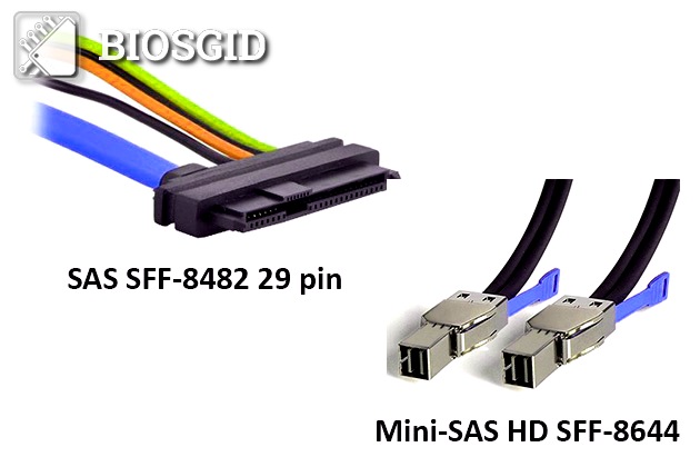
On the left - the internal SAS connector SFF-8482; On the right is the external SAS SFF-8644 connector with cable.
A few examples of the appearance of the strings and SAS adapters: the SAS-HD-Mini cord and the SAS-Serial ATA cord-adapter.
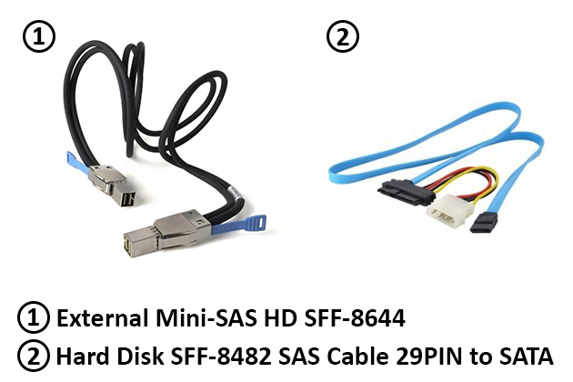
Left - HD Mini SAS cord; Right - an adapter cord with SAS on Serial ATA
Firewire - IEEE 1394
Today, you can often find hard drives with a Firewire interface. Although through Firewire interface to the computer you can connect any types peripherals, and it can not be called a specialized interface designed to connect exclusively hard disks, however, Firewire has a number of features that make it extremely convenient for this purpose.
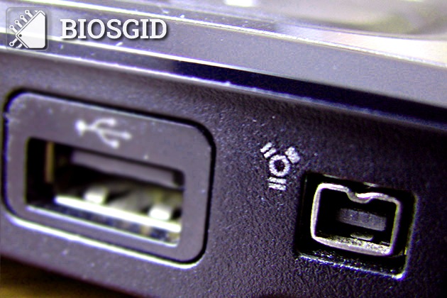
FireWire - IEEE 1394 - view of the laptop
The Firewire interface was developed in the mid-1990s. The beginning of development was laid by the well-known company Apple, which needed its own, different from USB, a bus for connecting peripheral equipment, primarily multimedia. The specification describing the operation of the Firewire bus is called IEEE 1394.
To date, Firewire is one of the most commonly used formats of high-speed serial external bus. The main features of the standard include:
- Ability to hot-plug devices.
- Open bus architecture.
- Flexible topology of connecting devices.
- Changing over a wide range of data transfer rates - from 100 to 3200 Mbit / c.
- The ability to transfer data between devices without the involvement of a computer.
- Possibility of organization local area networks by means of a tire.
- Transmission of power through the bus.
- A large number of connected devices (up to 63).
To connect HDDs (usually via external HDD enclosures) via the Firewire bus, a standard SBP-2 standard is usually used, using the Small Computers System Interface protocol set. It is possible to connect Firewire devices to a standard USB connector, but this requires a special adapter.
IDE - Integrated Drive Electronics
The abbreviation IDE is undoubtedly known to most users personal computers. The interface standard for connecting hard drives IDE was developed by a well-known firm that produces hard disks - Western Digital. Advantage of the IDE compared to other existing interfaces at that time, in particular, the interface of the Small Computers System Interface, as well as the standard ST-506, was the lack of the need to install a hard disk controller on the motherboard. The IDE standard meant the installation of a drive controller on the body of the drive itself, and on the motherboard there was only an interface host adapter for connecting the IDE drives.
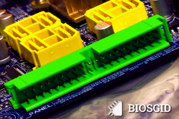
IDE interface on the motherboard
This innovation allowed to improve the parameters of the IDE drive due to the fact that the distance between the controller and the drive itself was reduced. In addition, the installation of the IDE controller inside the hard disk enclosure made it possible to simplify somewhat both the motherboards and the production of HDDs themselves, as the technology allowed manufacturers freedom in terms of optimal organization of the drive logic.
The new technology was originally called Integrated Drive Electronics (Built-in electronics). Subsequently, a standard describing it was developed, called the ATA. This name comes from the last part of the PC / AT computer family name by adding the word Attachment.
For hard wiring drive, or other device, such as an optical drive that supports Integrated Drive Electronics, to the motherboard, a special IDE cable is used. Since ATA refers to parallel interfaces (therefore it is also called Parallel ATA or PATA), that is, interfaces that allow simultaneous data transmission over several lines, its data cable has a large number of conductors (usually 40, and in recent versions protocol it was possible to use an 80-wire cable). A conventional data cable for this standard has a flat and wide view, but there are also cables of circular cross-section. The power cable for Parallel ATA drives has a 4-pin connector and is connected to the computer's power supply.
Below are examples of an IDE cable and a round PATA data cable:
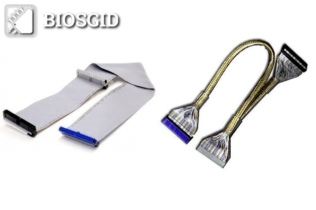
The appearance of the interface cable: left - flat, right in the round braid - PATA or IDE.
Due to the comparative cheapness of Parallel ATA drives, the simplicity of implementing the interface on the motherboard, and the ease of installation and configuration of PATA devices for the user, Integrated Drive Electronics drives have for a long time pushed other types of interface devices from the market for hard drives to personal computers.
However, the PATA standard has a number of drawbacks. First of all, this limitation on the length that a Parallel ATA data cable can have - no more than 0.5 m. In addition, the parallel organization of the interface imposes a number of restrictions on the maximum data transfer rate. Does not support the PATA standard and many advanced features that are available for other types of interfaces, for example, hot-plugging devices.
SATA - Serial ATA
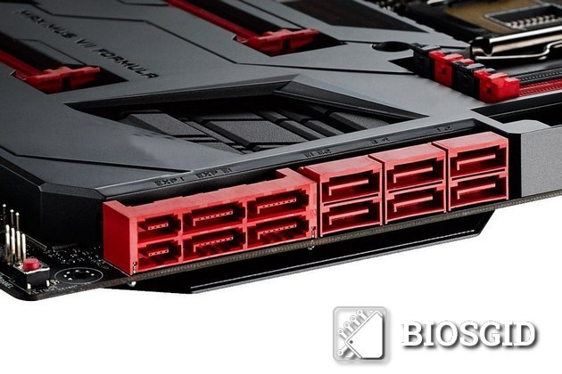
View of the SATA interface on the motherboard
The SATA (Serial ATA) interface, as you might guess from the name, is an improvement to ATA. This improvement is made, first of all, in the conversion of the traditional parallel ATA (Parallel ATA) into a serial interface. However, these differences in the standard Serial ATA from the traditional is not limited. In addition to changing the type of data transfer from parallel to serial, the connectors for data transmission and power supply have also changed.
Below is the SATA data cable:
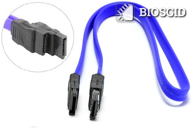
Data transmission cable for SATA interface
This allowed us to use a much longer cord and increase the data transfer rate. However, the downside was the fact that PATA devices, which before the advent of SATA were present on the market in huge quantities, could not be directly connected to new connectors. True, most new motherboards still have old connectors and support the connection of older devices. However, the reverse operation - connecting a new type of drive to an old motherboard usually causes much more problems. For this operation, the user usually requires a Serial ATA to PATA adapter. The adapter for the power cable usually has a relatively simple design.
Serial ATA to PATA Power Adapter:
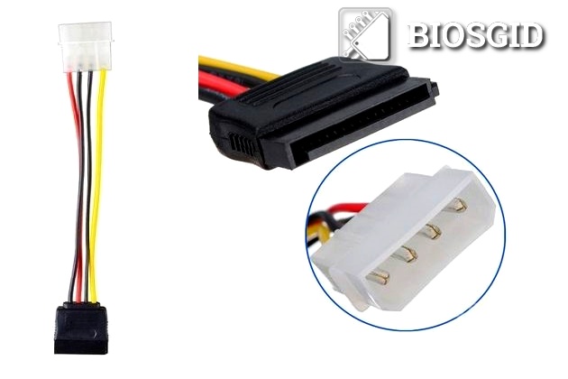
Left is the general view of the cable; On the right side is an enlarged view of the PATA and Serial ATA connectors
More difficult, however, is the case with a device such as an adapter for connecting a serial interface device to a connector for a parallel interface. Usually an adapter of this type is made in the form of a small chip.
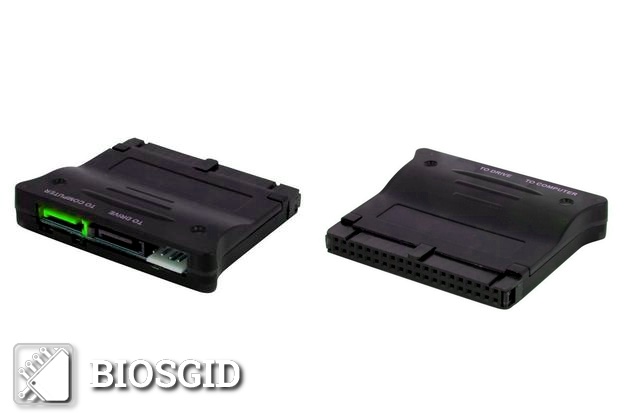
Appearance of the universal bi-directional adapter between SATA-IDE interfaces
Currently, the Serial ATA interface has almost supplanted Parallel ATA, and PATA drives can now be found mostly only in fairly old computers. Another feature of the new standard, which provided its wide popularity, was support.
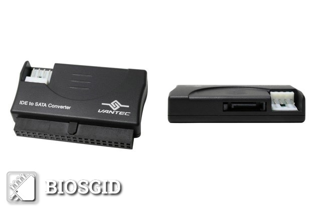
Type of adapter with IDE on SATA
On the technology of NCQ can be told a little more. The main advantage of NCQ is that it allows you to use ideas that have long been implemented in the SCSI protocol. In particular, NCQ supports the system of ordering read / write operations to several drives installed in the system. Thus, NCQ can significantly improve the performance of drives, especially hard disk arrays.
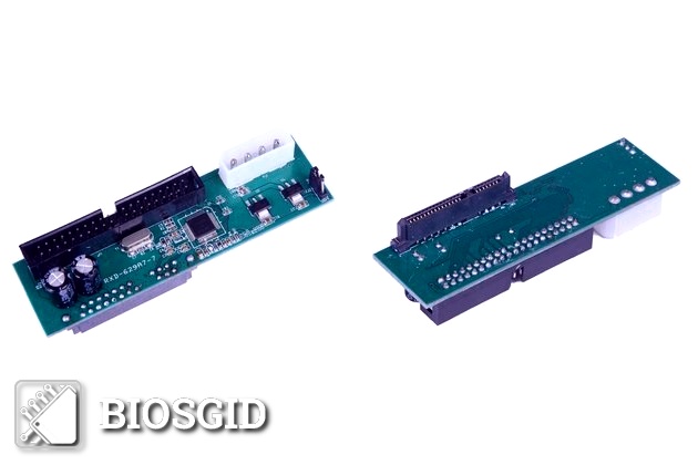
Type of adapter from SATA to IDE
To use NCQ, you need to support technology from the side of the hard drive, as well as the host adapter motherboard. Almost all adapters that support AHCI support NCQ. In addition, NCQ also supports some older proprietary adapters. Also, NCQ requires its support from the operating system.
eSATA - External SATA
Separately it is worth mentioning the seemingly promising in its time, but not widely disseminated format eSATA (External SATA). As you can guess from the name, eSATA is a kind of Serial ATA, designed to connect exclusively to external storage devices. The eSATA standard offers most of the standard features for external devices, i.e. internal Serial ATA, in particular, the same system of signals and commands and equally high speed.
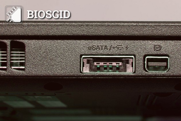
ESATA connector on laptop
Nevertheless, eSATA has some differences from the internal bus that generated it. In particular, eSATA supports a longer data cable (up to 2 m), and also has higher requirements for powering the drives. In addition, the eSATA connectors are slightly different from the standard Serial ATA connectors.
Compared to other external buses, such as USB and Firewire, eSATA, however, has one significant drawback. If these buses allow the power supply of the device through the bus cable itself, the eSATA drive requires special power connectors. Therefore, despite the relatively high data transfer speed, eSATA is currently not very popular as an interface for connecting external storage devices.
Conclusion
The information stored on the hard disk can not become useful to the user and is available for applications until the CPU of the computer accesses it. Hard disk interfaces are a means of communication between these drives and the motherboard. To date, there are many different types interfaces of hard drives, each of which has its advantages, disadvantages and characteristics. We hope that the information given in this article will in many respects be useful for the reader, because the choice of a modern hard disk is largely determined not only by its internal characteristics, such as capacity, cache size, access and rotation speed, but also by the interface for which it was developed.