Instructions
Restart the computer to enter the BIOS, and when the first screen saver appears, press the Delete key. Other options for the keys on different motherboards are possible, usually a message will appear on the screen saver like Press Del to enter setup. If another key is specified, for example, F2, press it to enter the BIOS.
Go to the Boot sector. The BIOS commands are controlled using the cursor buttons and the Enter key. Find the Boot device parameter - it is responsible for the boot sequence from the devices. Select the desired parameter with the arrow and activate it with the Enter key. Select for the first hard drive drive, select First Boot Device and press Enter, select HDD, and press Enter again.
Go to the Power section to set the BIOS settings for the cooler and processor. Turn on the control of the system cooler, as well as the CPU cooler. To do this, set the CPU Q-Fan Control option to Enabled, and select the Optimal option for the CPU Fan-Profile option.
Remove logo-logo download when you turn on the computer to speed up system boot. To do this, go to the Boot sector, select the Boot Settings Cohfiguration option, find the Full Screen Logo item, set this to Disabled.
Go to the Standard CMOS Setup section to configure the system date and time, as well as the settings hard disks computer. In the Integrated Peripherals section, you can set the interface settings, as well as additional system functions. To set the power and power options, go to the Power Management Setup section. The function of binding to the computer expansion cards can be set in the PnP / PCI Configurations section.
To determine the readings of the system sensors (processor temperature, fan speed), go to the Hardware Monitor section. To reset the BIOS to its default settings, go to Load Setup Defaults.
BIOS - base input-output system, basic system input-output - a set of parameters that determine the mode of operation of computer hardware. These settings can greatly affect the performance of the computer, affecting the performance of the processor, memory, hard drives, disk drives and other systems.
Before trying to set up bios, do backup copy important
Of course, you can configure bios and many other parameters, but we emphasize once again the seriousness of any operations with BIOS. As a rule, most bios settings are displayed in an optimal way, providing, if not the most productive, then the most reliable operation of the system.
note
Commands in different versions of the BIOS may differ slightly from those described above.
Introduction to the program, BIOS setup, which can also be called BIOS Setup Utility, CMOS Setup Utility or otherwise.
Very often the simplified names of this program are used, for example BIOS Setup or simply simple Setup. It's not so rare that this setup program is called and generally simple BIOS, although this is not very correct, for the simple reason that BIOS Setup - this is simply one of several components present in this program.
With the help of this program, it is possible to control the operation of the entire computer hardware, namely the processor, chipset, RAM and other components. The most important thing to remember at the beginning is that all the BIOS parameters are stored in the CMOS memory and not where else. It should also be noted that CMOS is basically insensitive to shutting down the computer, because of the energy consumption from a special battery on the motherboard.
Entering the BIOS Setup
To enter the program directly, you must press a certain key or a combination of these keys during the initial testing procedure. Please note that the most frequently used keys are Delete, a little less often F1 and F2; but there are other options. To know exactly which key is used to enter the BIOS Setup, first of all you need to look in the instructions to your motherboard or with the help of a hint that appears at the moment of passing the POST procedure, which will have, for example, the following: Press DEL to enter SETUP.If, nevertheless, you do not have such an instruction for some reason, and you can not see anything on the screen, do not be upset and try to try the most common variants:
- Delete;
- one of the function keys: F1, F2, F3, F10, F11, F12;
- Ctrl + Shift + S or Ctrl + Alt + S;
- Ctrl + Alt + Esc;
- Ctrl + Alt + Detete.
But even if this method did not lead to success, and you could not find the right key for entering BIOS Setup again, do not despair, there is another so-called trick trick.
Before turning on the computer, press and hold any key, and then turn on your PC. At boot, the system will necessarily detect a keyboard error and display a corresponding message on the monitor, in the text of which you can read the name of the "treasured" key necessary to enter BIOS Setup.
For example, a message like this:
Keyboard Error. Press F1 to continue, DEL to enter Setup (Keyboard error: Press F1 to continue or Delete to enter Setup). But also this method can not lead to the expected result, because in your BIOS Setup program you can simply turn off keyboard error control.
One of the most radical methods is a method that assumes a boot with a disconnected drive for floppy or hard disks, which will undoubtedly cause the system to display an error message with a possible mention of a hint about the name of the key for entering Setup.
But this trick would have been good 5-6 years ago, since the majority modern computers automatically determine the disk drives and this trick can be mildly expressed does not pass. But if you do not have the latest iron and decide to use this way, then very carefully unplug the cable from disk drive (required when the computer is turned off), and then turn it on. Please, do not use this method if you do not have the experience of assembling / disassembling the PC or your favorite computer for service.
Entering the BIOS Setup, the moment you press
It is not enough to know the name of the key for entering the BIOS Setup, it is very important to select the right moment to press it in the correct time. This moment comes immediately after the corresponding prompt appears on the screen, and if instead of a variety of POST messages on your monitor the manufacturer's logo is displayed, then try to press the Setup key several times with a certain interval, say 0.5-1 s.
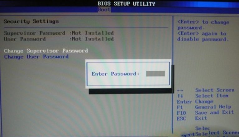
During the first attempt to enter Setup, you may encounter a surprise as a window with a prompt to enter a password. This means only that the previous user of the computer that worked with the BIOS Setup program before you simply protected it with a password.
BIOS Setup interface and methods for working with parameters
Basically, the BIOS Setup program assumes a text interface with the ability to control using the keyboard. In the main window of the BIOS Setup program there is a menu with a list of the main sections of the Setup program. This main menu BIOS Setup is usually presented in the form of two columns, this variant is inherent in different versions, such manufacturers as Award BIOS (Phoenix-Award BIOS) and AMIBIOS. I also want to note that the interface is used in motherboards of most manufacturers: Gigabyte, MSI, Foxconn, ECS, Abit and many others.
The second, so to speak, basic and common type of BIOS Setup interface is the menu bar at the top of the screen. This interface is used in PhoenixBIOS, Intel BIOS, as well as in certain versions of Award BIOS and AMIBIOS. This version of the interface is used on motherboards manufactured by ASUS, AsRock, Intel and others.
Not taking into account some minor differences between these BIOS Setup interfaces, all the techniques of working in sections with various parameters are in many respects similar. For example, to select the desired partition, subkey or parameter, you must use the arrow keys, and that to open them apply the Enter key.
Absolutely all sections of BIOS Setup have a similar structure.
- The name of the current section or sub-section is displayed at the top of the window.
- The left side lists all the available options for the selected partition. In addition to certain parameters, there may be names of subsections that have triangular arrows in their designation.
- To the right of the name of the parameters their current values are displayed. When a parameter and its values are displayed in a pale color, it means either it is read-only, or you need to change another associated parameter to edit it.
- In the right part of the window, as a rule, a brief information about the selected option is displayed, and at the bottom - a hint about the use of the function keys.
- In the BIOS Setup program, you can use the following control keys:
- Arrows to the right, left, up, down (cursor keys) - move the cursor by sections and parameters;
- Enter - Enter the selected section, execute the selected command, open a pop-up window with a list of values of the selected parameter;
- Page Up / Page Down or +/- to an additional numeric keypad - changing the values of the selected parameters; when you press these keys several times, it is possible to sequentially search through all the valid values of this parameter;
- Esc - exit from the section to the main menu, and when you click in the main menu - exit the BIOS Setup with the cancellation of all changes;
- F1 - call the BIOS Setup help;
- F2 - Change the color palette of the BIOS Setup program (this setting is not available in all versions of the BIOS);
- F5 - restoring the previous values for the selected partition: the values that were present at the time of entering the BIOS Setup program will be returned (in some versions of the BIOS this key is used to set the default values);
- F6 - setting for the selected section of the default values (the Load Fail-Safe Defaults command); in some versions of the BIOS, F5 or F9 keys can be used for this purpose;
- F7 - an optimized value is set for the selected partition parameters (Load Optimized Defaults);
- F10 - exit from the BIOS Setup with saving all the changes made, while confirming the actions with the Y and Enter keys.
ATTENTION: In some BIOS versions, the values of the F1-F10 function keys may be different, so it is better to check the manual for the motherboard or the prompt at the bottom of the screen before using them.
Exit the BIOS Setup
There are two ways to exit the BIOS Setup:
- exit with cancellation of all changes made;
- exit with saving all changes made.
This method should be used in the following cases:
- when you have no plans to make any changes, but only a desire to just look at the current value of any parameter;
- if you are not completely sure of the correctness of the actions you have taken, or if any parameter was accidentally changed.
In order to exit with saving all the changes you made in the program, you must select the command in the main window of the program Save and Exit Setup, after which a message box should appear SAVE to CMOS and EXIT (Y / N). You should press the keys Yand Enter, with all the settings that you have changed will remain saved, and your computer will continue to download. And if you still have changed your mind about making changes in CMOS, then you should click Nand Enter or use the key Esc.
This exit method is only used when you are absolutely sure of the correctness of the decisions you made and you know for sure that you did not make any mistakes or errors during the parameter editing procedure.
In the event that the BIOS setup program with the top menu bar is applied on your computer, select Exit in the main menu window, in which you need to find all the above commands Exit Without Saving or Save and Exit Setup.
Examples of editing BIOS Setup parameters
For those visitors who do not have experience with the BIOS, we'll take a closer look at one of the most typical examples of using BIOS Setup. So include the imagination, imagine that you need to boot the computer from a bootable CD, say, with the operating system distribution windows systems. To do this, you first need to change the boot order itself in the BIOS so that the CD-ROM drive is the first in the so-called list boot devices. In the event that the BIOS on your computer has an interface with the main menu in two columns, then the sequence of your actions should be the following.- To restart a computer.
- At the initial stage of the self-test (POST), you must press the BIOS entry key, which is basically Delete or F2. Wait until the main BIOS Setup screen appears. If you are late and you did not press the Setup key in time and the operating system started to boot, you should restart your computer and try again.
- With the help of the cursor keys you need to select the section necessary for you in the main program window, in our specific case this is Advanced BIOS Features, and press Enter.
- It is very important to remember, and it is better to write down the current values of the parameters of the selected section so that in case of careless actions on your part you could return all the initial values of the changed parameters.
- The parameter that defines the first boot device is usually called First Boot Device (1st Boot Device); Select it from the list using the arrow keys. And for him you will need to set the value of CDROM or CD / DVD.
- Exit to the main program window with the Esc key.
- To completely exit the BIOS Setup and save any changes you have made, run the command Save and Exit Setup, and in the window that appears, confirm these intentions with the Y and Enter keys.
- To check the validity of the changes made, do this by booting from the CD.
- Again, you must restart the computer and return the previous value of the parameter First Boot Device, then boot the computer in the normal mode.
You can change the value of the selected parameter in one of two ways:
You should successively press the keys Page Up / Page Down (or +/- on the additional numeric keypad) until the desired parameter value is set;
Press Enter, select the required value in the appeared window and press Enter again; This option is more convenient, but it is not supported by some older versions of the BIOS.
ATTENTION: Do not ever leave the BIOS Setup while retaining the changes, if you are affected by any parameter due to incalculability or curiosity. In this case, you need to exit the BIOS Setup with the cancellation of all the changes made, then again enter and re-edit the desired parameter.
For all BIOS versions in which a menu with a horizontal line is used, the sequence of actions to be performed will be slightly different.
- Restart the computer and enter the BIOS Setup.
- Use the arrow keys to select the section in the main menu of the program Boot. Remember or record the current settings.
- Use the arrow keys to select an option 1st Boot Device and set the value for it CDROM (CD / DVD) one of the methods described above. This parameter can also be found in the subsection Boot Device Priority.
- Use the arrow keys to go to the section Exit and execute the command Exit and Save Changes. Confirm your actions by pressing Enter in the dialog box that appears.
- Boot from the CD, and then return the previous value of the parameter 1st Boot Device.
As you have already guessed from all of the above, working with BIOS Setup is associated with a certain risk, due to the fact that if the parameters are unsuccessful or careless, the functioning of the system will not be stable or completely absent. There are several simple and most importantly effective tips, which, in principle, will help to reduce possible risks to a minimum.
- Try not to experiment at all with BIOS on computers that process or store important information. Before you configure or overclock the system with using BIOS you must take care of reserving important data.
- Before changing parameters, you should always remember, and it is best to record their old and new values. This will easily allow you to restore the previous state of the system if you do not like the work of the computer with the new settings or it will not work very stable. Specific versions BIOS can save the current system settings as a file, but in the vast majority of cases all these parameter values you have to write down manually. You can, of course, take pictures bIOS screens Setup digital camera as an option is also not bad.
- You do not need to change those parameters whose values you do not know or understand. If the book does not describe the parameter you are interested in, you can always refer to the manual on the motherboard. Well, if there is no manual, then it's worth trying to search the electronic version of this manual on the manufacturer's website motherboard.
- You should not edit a single set of absolutely unrelated parameters. If the system crashes, it will be very difficult for you to determine which of the changed parameters caused this problem, and as a result you will have to start everything from the very beginning.
- Never need to deal with overclocking a computer without the need and the corresponding preparation. If an attempt is unsuccessful, your computer may simply not turn on, and in some rare cases the processor, chipset and other important components of the system may burn.
- AT the BIOS Setup of old antediluvian computers can still be found in the section Hard Disk Utility, which as you guessed is intended for a low-level hard formatting disk. The main thing to remember is that every low-level formatting destroys completely all the data on the disk, and sometimes even can disable the hard drive.
BIOS, restore the system to life
Unfortunately, in real life not everything can always be foreseen, and it's not uncommon for cases when after making changes to the settings BIOS computer does not work normally or does not work at all. And if it seems to you that the reason is just the wrong setting of the BIOS parameters, then you can return the system to life with the help of a few simple tips.
- If, after restarting your computer, you have the opportunity to enter the BIOS Setup, you must immediately set the old values of the parameters you changed. As we advised above, all changes in the system must be recorded in advance.
- In the event that you did not heed our advice and did not record the changes you made, you should not change all the parameters in a row, this will only increase the hopelessness of the situation. In this case, you can only try to restore the system by loading the default settings using the command Load Fail-Safe Defaults. After that it will be necessary to re-optimize the system.
- It happens that the computer does not want to be included at all only because of incorrect settings BIOS. With this variant of the development of events, one can not do without an autopsy the system unit and reset the contents of the CMOS using a special jumper on the system board. And as you probably guessed, after this procedure you will need to reconfigure the system.
That's all. Thank you for reading the article. I hope it was helpful to you.
If you were looking for BIOS settings in pictures, then you were at the right address.
Protect the changes made will be a lithium battery built into the motherboard and supporting the required parameters with loss of voltage. Thanks to the program, it is possible to establish a stable interaction of the operating system (OS) with PC devices.
Attention! The present Boot network configuration section allows you to adjust the parameters relating to the system boot speed, keyboard settings with the mouse.
After you finish the work or get acquainted with the Bios Setup Utility menu, you need to press the burning Exit key, which automatically saves the changes you made.
Main section - Main menu
We'll start with the MAIN section, used to modify the settings and adjust the time scales.
Here you can customize the time and date of your computer, as well as make settings for connected hard drives and other drives.
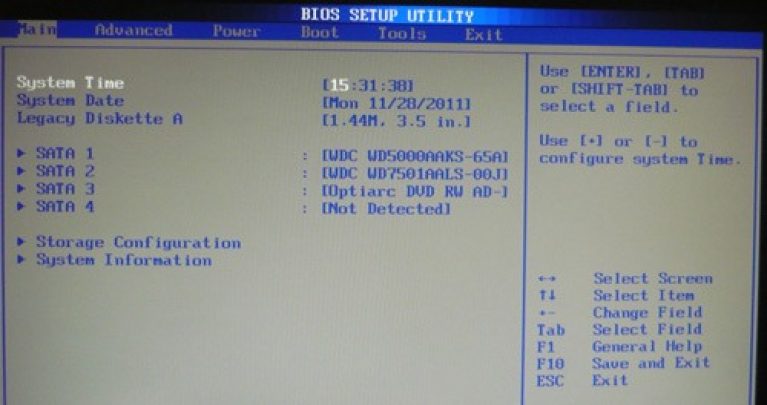
To reformat the mode of the hard disk, you need to choose a hard disk (for example: "SATA 1", as shown in the picture).
- Type - this item indicates the type of connected hard drive;
- LBA Large Mode - is responsible for the support of drives with a capacity of more than 504 MB. Therefore, the recommended value here is AUTO.
- Block (Multi-Sector Transfer) - For faster operation, we recommend selecting the AUTO mode;
- PIO Mode - It includes the operation of the hard disk in the old mode of data exchange. Here it will also be best to choose AUTO;
- DMA Mode - gives direct access to memory. To get a higher reading or writing speed, select AUTO;
- Smart monitoring - this technology, based on the analysis of the work of the drive is able to warn about a possible disk failure in the near future;
- 32 bit Data Transfer - the option determines whether the 32-bit mode of communication will be used by the standard IDE / SATA controller of the chipset.
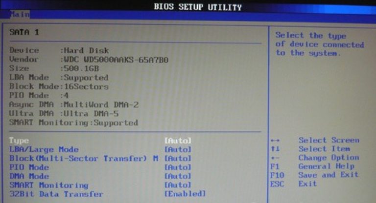
Everywhere, using the "ENTER" key and the arrows, the Auto mode is set. The only exception is 32 Bit Transfer, which needs to be set to Enabled.
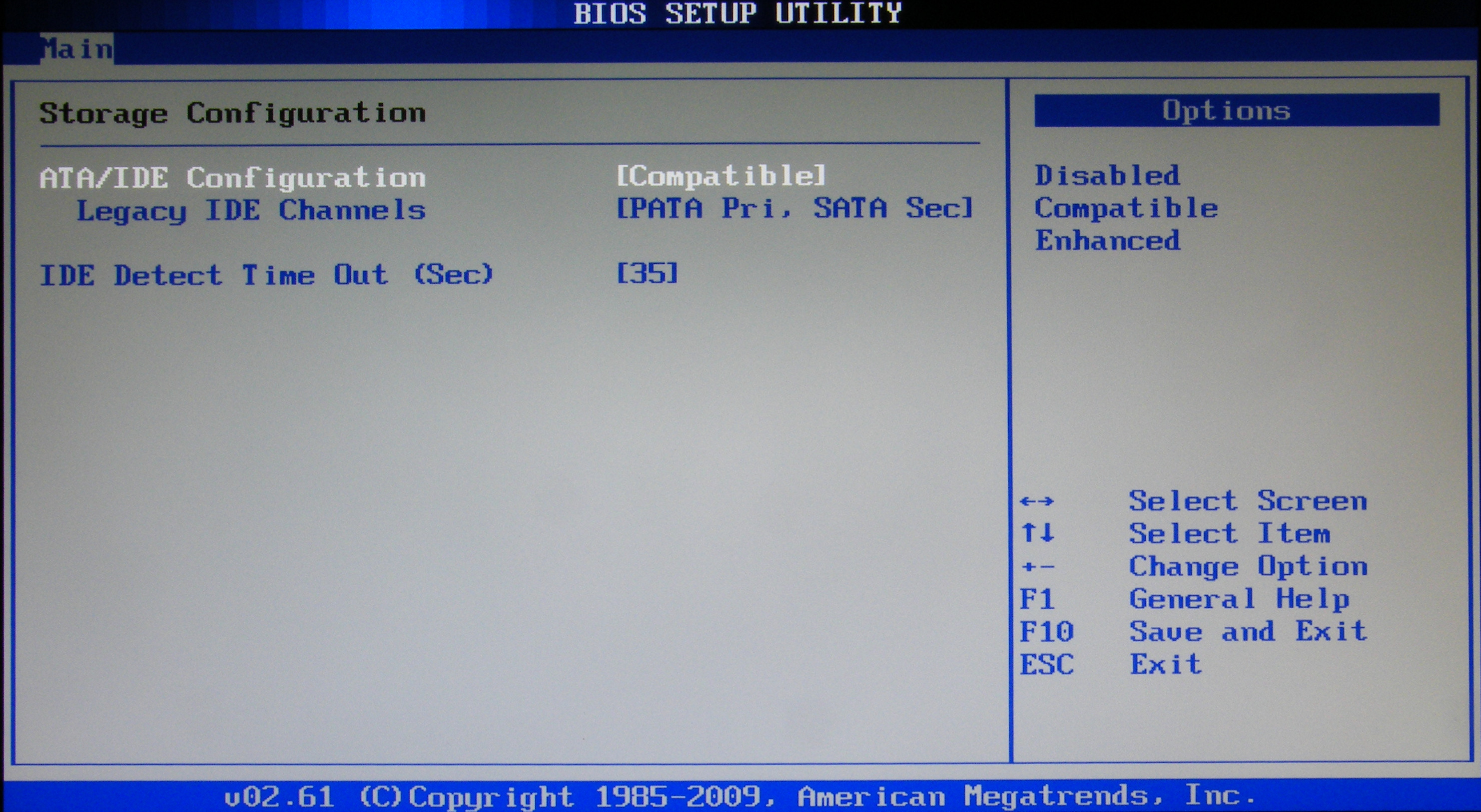
Important! It is required to refrain from changing the option "Storage Configuration", which is located in the "System information" section and prevent correction "SATADetectTimeout. "
Advanced section - Advanced settings
Now proceed to the settings of the basic PC nodes in the ADVANCED section, which consists of several sub-items. Initially, you will need to set the necessary processor and memory parameters in the Jumper Free Configuration menu.
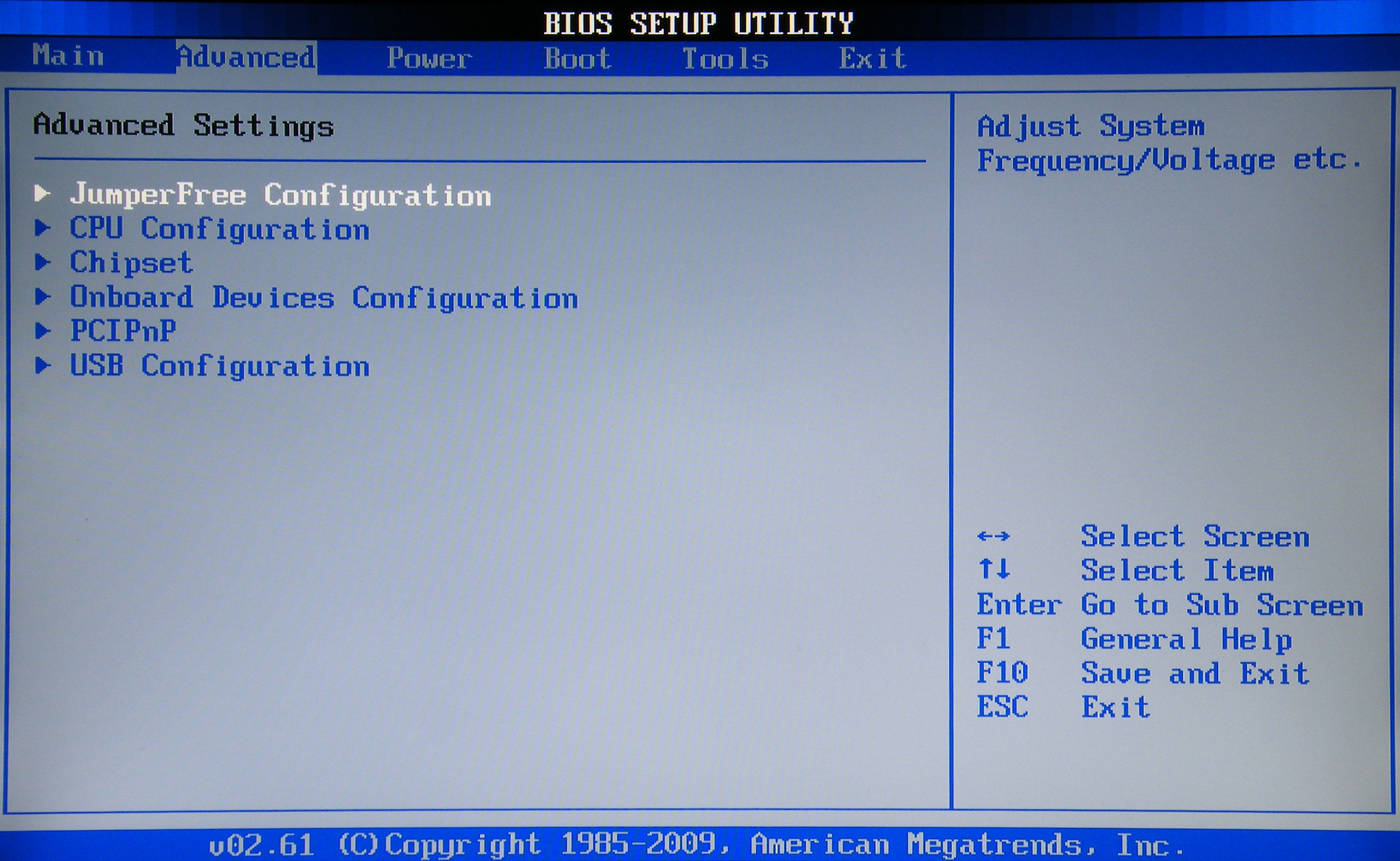
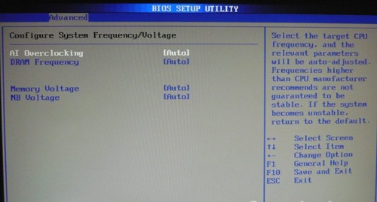
By selecting Jumper Free Configuration, you will go to the Configure System Frequency / Voltage subkey, here you can perform the following operations:
- automatic or manual overclocking of the hard drive - AI Overclocking;
- change clock frequency of memory modules -;
- Memory Voltage;
- manual mode for setting the voltage of the chipset - NB Voltage
- change of port addresses (COM, LPT) - Serial and Parallel Port;
- setting of controllers settings - onboard Devices Configuration.
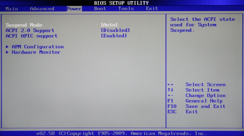
Section Power - PC Power
The POWER item is responsible for powering the PC and contains several subsections that require the following settings:
- Suspend Mode - We set the automatic mode;
- ACPI APIC - set to Enabled;
- ACPI 2.0 - We fix the mode Disabled.
BOOT section - load control
Direct downloading is controlled using the parameters found in the BOOT section. Here it is allowed to determine the priority drive, choosing between a flash card, a drive or a hard drive.
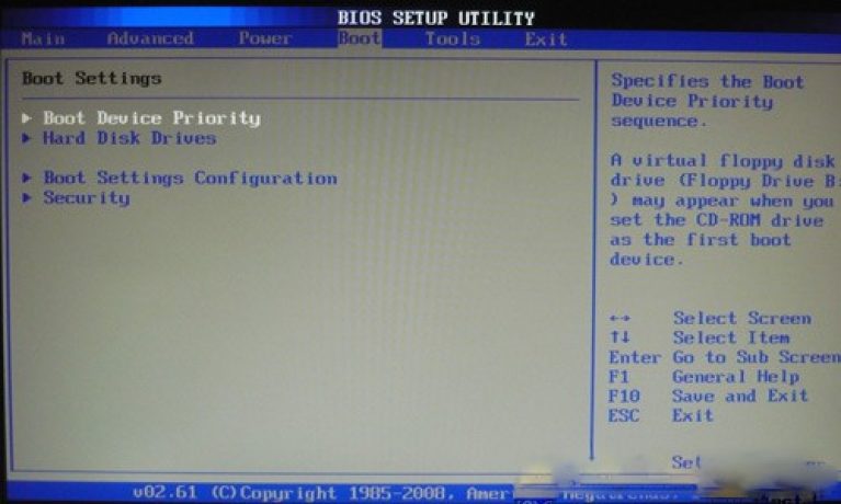
If there are several hard disks, then in the Hard Disk sub-item the priority hard drive is selected. The boot configuration of the PC is set in the Boot Setting subkey, which contains a menu consisting of several items:
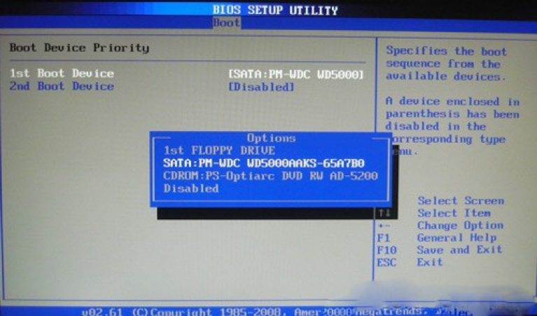
Choosing a hard drive
The boot configuration of the PC is set in the Boot Setting subkey,
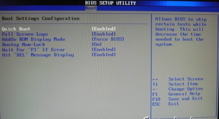
- Quick Boot - acceleration of OS loading;
- Logo Full Screen - disabling the screen saver and activating the information window containing information about the boot process;
- Add On ROM - setting the order on the information screen of modules connected to motherboard (MT) by means of slots;
- Wait For 'F1' If Error - Activation of the function of forced pressing "F1" at the time of identification by the system of an error.
The main task of the Boot partition is to determine the boot devices and set the required priorities.
Attention! If you want to restrict access to the PC, set the password toBIOS in subsectionSupervisorPassword.
After the publication of a series of materials on the dispersal of computer components, we began to receive questions from readers who discovered ignorance of the elementary things connected with setting up the BIOS of motherboards. We mentioned that overclocking should be approached by already having initial theoretical knowledge in this field. However, in all likelihood, many users of PCs are interested in getting a free performance boost (and not only).
This material is intended to help beginners navigate the issues basic settings system.
The article will deal with fairly simple concepts related to working with the configuration of firmware firmware. First of all, I'll explain the BIOS abbreviation - Basic Input / Output System (basic input / output system). This is a kind of software written in a chip with nonvolatile memory, which allows you to start initializing the components of the PC, setting their operating modes. The BIOS contains the microcode needed to manage the keyboard, video card, disks, ports, and other devices. For the average user, the BIOS is identified with a visual shell, which allows you to change the settings of the computer if necessary.
Note also that the answers to most of the issues raised in this material can be found in the manuals for the operation of motherboards. Alas, few of the users who want to learn everything at once, draw attention to the brochures that come with these products. Sometimes the manuals are scanty enough, but there's nothing to prevent them from acquainting themselves with those devoted to other boards of the same (or other) manufacturer - the basic BIOS options are standard, and what is applicable to one firmware is often useful when working with another one. Mastering this material contributes to the knowledge of English - a banal translation of terms will help you find the necessary parameters.
What kinds of BIOS are there?
The differences in firmware are reduced not only to the abundance of settings and the adjustment ranges of individual parameters. First of all, it is a microcode of a certain developer, which ultimately determines the visual envelope. For example, the motherboard BIOS from ASUS is based on AMI code (menus with blue characters on a gray background), most manufacturers use Award / Phoenix (blue background, yellow letters). Extensible interfaces of EFI firmware (Extensible Firmware Interface), which are distinguished by the extraordinary graphical interface. They allow you to navigate using not only the keyboard, but also the mouse, and the menu items become even more intuitive.
How to get into BIOS
In order to enter the BIOS, it is necessary to press the corresponding button on the keyboard during the initialization of the PC devices (POST procedure). If the firmware of the motherboard is based on the microcode from AMI - it will be F2, Award - Del. In order to get into the BIOS of some laptops, you need to activate the F8 key. However, even if you do not know which firmware the firmware of the board is based on, during the initialization of devices on the screen a hint will appear (for example, Press F2 to Enter Setup - "Press F2 to get into the settings section"). If the monitor does not turn on in time, after turning on the PC regularly and often press the necessary button or, if you are not sure which one, try Del, then F2.
Selecting and changing the firmware settings
BIOS settings are controlled exclusively from the keyboard. To move the cursor, use the arrow key (Up, Down, Right, Left). To change the desired parameter, highlight it with the cursor, press Enter and select one of the available modes. If BIOS board based on the microcode from AMI, for the same purpose you will have to use the "+" and "-" buttons. Certain values can be set directly from the numeric keypad (for example, if you need to change the system bus frequency from 266 to 320 MHz by hovering over the corresponding position, enter 3, 2, 0, then Enter). To go up one level of the menu up, press the Esc key, exit the BIOS - we perform the same operation in the root directory. Often it also provides decoding options for managing the settings of the firmware. When you exit the BIOS using the Esc key (without saving the settings) or F10 (with saving the settings), a window will appear with a question. Do you want to exit / save the settings? To confirm, we press the Y (Yes) button, to cancel - N (No).
BIOS basics in pictures
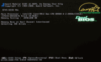 |
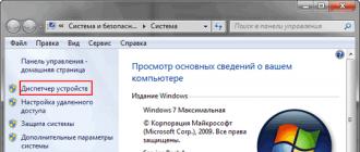
| The system undergoes the initialization procedure (POST). To get to the BIOS, at the moment, you need to press the Del key (this is indicated by the inscription in the lower left part of the screen) |
 |
| The main BIOS menu of one of the motherboards manufactured by Gigabyte. Below are brief tips - descriptions of the purpose of individual keys |
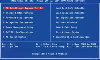
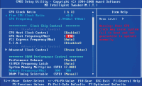 |
| The section on fine-tuning modes of operation of the main components of the system (processor, random access memory), can be called differently. In this case, this is MB Intelligent Tweaker (M.I.T.) |
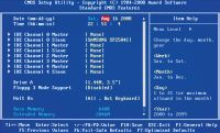 |
| Standard CMOS Features - The menu item available in the BIOS of any board. Allows you to set the date and time, as well as view the list of FDD, IDE and SATA devices connected to the system |
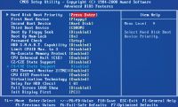 |
| Advanced BIOS Features, or Options, - one of the most important sections related to the configuration of the system. In our case, there is an opportunity to control the priority of the download, individual technologies of the CPU and visual design of the splash screen |
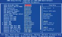 |
| In chapter Integrated Peripherals The functional blocks implemented on the motherboard are activated ( network Card, audio codec, IEEE 1394, USB-ports, IDE- and SATA-controllers), their operating modes are set |
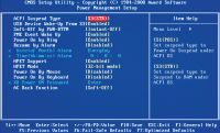 |
| Power Management Setup - power management of the computer, on / off without using the button Power the system unit |
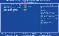 |
| In subcategory PnP / PCI Configurations there is nothing interesting for the ordinary user. There are hidden system address settings |
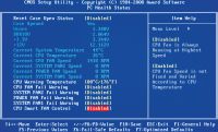 |
| System Monitoring Section - PC Health Status. Allows you to track temperature regime work of PC components, main supply voltages, monitor the number of revolutions of system fans |
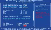 |
| In this BIOS, the control parameters that are important for overclocking a PC are concentrated in one section. Otherwise, it may be the case with the settings of the boards using AMI firmware - similar options are sometimes placed in different subcategories of the main menu |
BIOS updates - is it worth doing this
Manufacturers at the time of the announcement of a certain model of the motherboard do not always have time to develop an optimal firmware for it. Therefore, over time, BIOS updates are available, available for download from official sites of manufacturers. The list of improvements that this or that version of the firmware has is often given in the description. Is it worth constantly updating the BIOS of the motherboard? If the PC is working well, and the overclocking of components is not limited to the board, then you do not need to do this. Change the firmware should be only with significant changes in certain parameters, the expansion of functionality, sometimes - the introduction of support for new processor models.
Information on how to update the firmware is also present on the manufacturers' websites. Owners of modern products do it directly from under the OS, using specialized utilities. To update the firmware of old boards, you need to get a drive. When upgrading the BIOS, be extremely careful - power failure, premature pressing of the Reset button before the operation is completed - and the motherboard will have to be sent to the service center. Hanging may be caused by flaws in the utilities from the manufacturers. So do not overdo it in pursuit of each new version BIOS, because from the good of good are not looking.
After changing the settings, the computer does not boot. What to do?
A typical situation that accompanies overclockers is the inability to boot the PC after installing incorrect parameters in the BIOS. Many modern motherboards implement resetting technologies in such cases. However, they do not always work, and not all boards are equipped with them. But this is not an excuse to get upset, panic and say that the computer has broken down. On any motherboard there is a special jumper for forced resetting of all settings to the Default mode, which is often denoted as CLR_CMOS (or Clear CMOS). Its placement is always indicated in the manual of the board. The jumper may look like a special button on the back panel (a similar solution is found on the ASUSTeK top boards), or be disconnected in the vicinity of the battery. If it has three contacts, two of which are closed by a jumper (this is the scheme used in most products), it is necessary to switch the jumper from one position to another (for example, 1-2 → 2-3) with the computer turned off for a few seconds and back. Sometimes a jumper has only two contacts (often found on Gigabyte boards), then they must be connected with a conductive object (for example, a screwdriver).
If after zeroing the system passes the POST initialization procedure, but the OS does not boot, make sure that the hard disk is displayed in the BIOS and it is placed under the first number among the available boot devices. If you use a HDD with an IDE connector on modern motherboards, you will probably have to configure the mode of the external controller (Configure SATA Interface as IDE). After carrying out the described manipulations, the system should successfully boot, with the exception of cases when the OS is out of order (such complications are possible, especially with a long game with memory timings settings, but rarely occur).
Base BIOS partitions - where to what to look for
A novice user does not need to thoroughly study each item of the firmware in order to set up the system. Therefore, we will briefly describe the main features available in the BIOS of all boards.
From the basic sections, select Standard CMOS Features, Advant-ced BIOS Features and Integrated Peripherals. The first one displays the current date and time, the amount of RAM, lists the IDE and SATA-compatible system devices. It is also possible to change the clock's performance through the OS, so the value of the section lies in the initial diagnosis of the PC: it tracks which drives, hard disks are connected and defined on the hardware level, and which are not. In Advanced BIOS Features (or the Boot menu, if the firmware is based on AMI code), the priority of the boot sequence is set. There are cases when the operating system on the HDD is not initialized simply because the FDD in which the floppy disk is located or the CD-ROM with the boot disk is the first in the device list. Do not expect to see the OS yet. Immediately put the first hard drive - never go wrong. The Integrated Peripherals section is interesting in that it allows you to disable the controllers unplugged on the motherboard, thus controlling the functionality of the PC. If your system does not have sound when the speakers are connected correctly - check if the audio codec is activated (the submenu value must be Enabled or Auto). The situation is similar with the network controller, IEEE 1394, etc. Pay attention to the points about USB. Be sure to activate the appropriate controller, turn on keyboard and mouse support with USB interface. Depending on the positioning of the motherboard, its features in the sections Advanced BIOS Features and Integrated Peripherals may contain different system settings. To briefly study the proposed settings in them, you should pay attention.
Among the boards available in the BIOS of most boards, we also select the sections of the system monitoring (PC Health Status), power management (Setup) and configuration of data bus addresses (PnP / PCI Configurations). The latter two are of no interest to most. The most valuable for the average user is the monitoring section, which displays the temperatures of the main components of the PC (CPU, chipset) and the current voltage supplied by the power supply, and there is the possibility to control the speed of the fans. However, unconditionally trust these sensors is not necessary - their testimony is inaccurate.
Settings that determine the speed of the PC, the operating modes of the main components, are located in one or more adjacent subsections of the BIOS. It is possible that they may not be at all - do not expect to find a cheap motherboard for office computer options for a serious increase in supply voltages, setting timings of RAM, control over the parameters of the CPU. More about the relevant items, we told in the materials devoted to overclocking the PC, so now we will not dwell on them.
Most of the parameters available for modification through the BIOS can be installed directly into the OS using specialized utilities. However, this method is often inconvenient - every time you start the computer you need to run additional software, activate certain settings. When you reinstall the system, they will be lost. Therefore, if you want to be with your computer on "you", you will have to learn the BIOS of the motherboard.
Afterword
Perhaps this material does not describe all the nuances of working with the BIOS, which would like to know the newcomers. However, do not worry if you have not found the answer to the question you are interested in, first of all, remember where the manual for the motherboard is located, and carefully study the section on the firmware. If there is no brochure or the description is too scant - you can download the extended version from the official website of the motherboard manufacturer for a particular product or simply find a good guide from a third-party manufacturer. It is likely that the settings mentioned in it will be similar in many respects. Not sure - ask at specialized forums for thematic resources, although we do not see anything wrong with the self-study of the BIOS by trial and error. The "magic" jumper CLR_CMOS for resetting settings is available on any board, and it's almost impossible to spoil any accessory, without fundamentally changing the power settings (for example, increasing the voltage on the processor by 80% of the nominal value).
If after careful study of the BIOS of the motherboard installed in your PC, it suddenly turns out that there are no specific settings, do not be upset. On Gigabyte products to activate the section responsible for fine-tuning the memory subsystem and the CPU operating mode, after entering the BIOS, you need to press the key combination Ctrl + F1. In other cases, it is possible that there are really some options. A similar situation is typical for budget fees. In their firmware sections for fine-tuning, power management of PC components are either very scarce or completely absent. However, it is likely that the required parameters can be changed from under the operating system with the help of specialized utilities.
A couple of words need to be said about the new interface - EFI - coming to replace the classic BIOS. Undoubtedly, a pleasant graphical shell will appeal to individual users, but it is worthwhile to judge the convenience of its implementation by testing only the corresponding products. While experienced overclockers are quite satisfied with the available opportunities, in which full customization The BIOS of the motherboard for optimizing the parameters of all components and overclocking the PC takes from several tens of seconds to a minute. Too fast? By no means. Learn the basics of working with the configuration of firmware, expand your knowledge, and it is possible that over time you will become specialists in this field.
A few simple tips for optimizing the BIOS to speed up the loading and running of the computer:
1. Go to the BIOS, because they are all different, then I can not say exactly the location and names of options, as well as guarantee their availability, but the options are pretty standard and are present on most computers. So right after restarting the computer we go into BIOS (usually by pressing Delete, less often F2, F1, Ctrl-Esc).
2. Find the sequence of devices to load (Boot Sequence or something like that). We put the first HDD-0 or IDE-0, i.e. Your main hard drive, all other devices (from 2 to 4) disable (if you need to boot from a floppy disk or CDROM, then you will need to change these options again, but on many motherboards there is one undocumented option - pressing several times Esc at boot time when there is auto-detection of hard disks - leads to the appearance of a boot menu from different devices).
3. Disable Boot Other Device - you do not need the BIOS to search for something on boot.
4. Disable Boot up Floppy Seek - do not yank the drive at boot.
5. If you do not use the USB port, it is advisable to put it in Disable in the BIOS - this prevents it from pollning at the time of loading and loading its driver in Windows, which is still not used.
6. We put Enable Fast Boot, Fast memory test, if you have these options.
7. If there is a possibility, you should also make auto-detection of hard drives and CDROMs in the BIOS and remember them so that the BIOS does not test them every time.
8. Disable the virus scan.
Save the changes and ready - if you had any other options, you will get a significant acceleration of computer loading, sometimes 2-3 times. Of course this configuration is for daily work, if you need to debug a computer or reinstall the operating system, then most likely you will have to put something else.
There are viruses (for example, Win95.CIH) that destroy the contents of the Flash BIOS by writing random data ("garbage") into it. As a result, after the first reboot, the computer stops loading. And, as a rule, even in industrial conditions to restore the contents of Flash BIOS and restore the computer to work is quite difficult. I RECOMMEND all users of modern computers to install the SWITCH on the computer's motherboard in a position that prohibits RECORDING in the Flash BIOS! Otherwise you can FOREVER lose your computer FOREVER!
Sometimes you need to slow down the computer for some old programs or for debugging and testing your own programs on a weak computer. You can, of course, download a fairly large number of slow-blows, but you can do without them. If you have the option "Internal Cashe" and "External Cashe" in the BIOS, disable them (both or some one), which will ensure a decrease in performance by at least an order of magnitude.
BIOS Settings
- Advanced - In this section, you can configure the operation of the chipset of the motherboard, which allows you to increase the performance of your computer when properly applied. In other versions, the BIOS can be named Chipset Features Setup or Advanced Chipset Setup
- Advanced Chipset Setup - In this section, you can configure the operation of the chipset of the motherboard (see also Advanced, Chipset Features Setup)
- Boot Virus Protection - Setup allows you to determine the presence of a virus in the boot sector. Prior to booting the operating system, the BIOS overwrites the boot sector into a special area of flash memory and stores it there. Before downloading, the system compares copies of the boot sector with its original on the hard disk. If a difference is detected, a warning message will appear on the monitor screen. Can be set to Enabled or Disabled. There is also another name for the setting: BootSector Virus | Detection.
- Boot Up Floppy Seek - This setting allows you to enable the boot diskette search function. When the system is on, the system searches for the floppy drive at boot time. In this case, the drive format is determined - 80 or 40 tracks and its operability. This is an outdated setting that you can turn off. It can take the values Enabled (each boot is searched for a bootable floppy disk) and Disabled (disabled, set by default). There is also the name Floppy Drive Seek At Boot.
- Chipset Features Setup - In this section, you can configure the operation of the chipset of the motherboard (see also Advanced, Advanced Chipset Setup)
- CPU Level 1 Cache - setting for the L1 processor cache (Enabled).
- CPU Level 2 Cache - setting for the L2 processor cache (Enabled).
- Daylight Saving - this parameter controls the automatic translation of the clock to daylight saving time. Possible values are: Disable or Off (automatic daylight saving is disabled) and Enable or On (automatic daylight saving time is enabled). Windows has its own settings for transferring the clock to daylight saving time.
- Date (mm: dd: yy)
- Floppy Drive Seek At Boot - see Boot Up Floppy Seek
- Jumper free Configuration - frequency and voltage settings for CPU memory.
- Legacy Diskette A (B) - The types of drives A and B are installed. Main is one of the main BIOS partitions in which standard settings computer, allowing you to set basic information, as well as set the system date and time. In other versions of the BIOS, the name Standard CMOS Setup occurs.
- Primary IDE Master - setting the parameters of the first master IDE device in master mode.
- Primary IDE Slave - setting the parameters of the first master IDE device in slave mode.
- Quick Power On Self Test - Quick memory testing. In the on state, you can avoid repeatedly testing the memory when the computer is turned on. You can disable it, because if you have memory problems, this test will not help (Enabled - Disabled).
- Secondary IDE Master - setting the parameters of the second IDE device in master mode
- Secondary IDE Slave - setting the parameters of the second IDE device in the slave mode
- System Date - This setting allows you to set or change the system date (number, month, year).
- System Information - system information
- System Time
- Time (hh: mm: ss) - This setting allows you to set or change the system time.
Signals that the BIOS issues
Manufacturers of BIOS include in their programs a system for alerting them to problems by means of audio signals issued by the system speaker. This allows you to determine the source of the problem of computer malfunction.
Award BIOS
No signals - The power supply is defective or not connected to the motherboard.
Continuous signal - The power supply is defective. Replacement is required.
1 short beep - No errors were found. A typical behavior of a working computer is that the computer boots normally.
2 short beeps - Minor errors detected. The screen prompts you to enter the CMOS Setup Utility to correct the situation. Check the reliability of the loops in the connectors of the hard drive and the motherboard.
3 long signal - Keyboard controller error. Restart the computer. You may need to replace the motherboard.
1 long + 1 short beeps - There are problems with RAM. Check that the memory modules are installed correctly. Or replace it with other memory modules.
The problem with the video card is the most common fault. It is recommended to remove the board and insert it again. Also check the connection to the video card monitor.
Key initialization failed. Check the connection of the keyboard with the connector on the motherboard.
1 long + 9 short beeps - An error occurred while reading data from the permanent memory chip. Reboot the computer or reflash the contents of the chip (if this mode is supported).
1 long repeating signal - Incorrect installation of memory modules. Try to pull and paste them again.
1 short repeating signal - Problems with the power supply. Try to remove the accumulated dust in it.
AMI BIOS
No signals - The power supply is defective or not connected to the motherboard.
1 short beep - No errors were found. The computer is ready for use.
2 short beeps - Memory parity error. Restart the computer. Check the installation of memory modules. Memory modules may need to be replaced.
3 short beeps - An error occurred while running the main memory (the first 64 KB). Restart the computer. Check the installation of the memory modules in the slots. Memory modules may need to be replaced.
4 short beeps - The system timer is defective. You may need to replace the motherboard.
5 short beeps - The CPU is faulty. You may need to replace the processor.
6 short beeps - The keyboard controller is defective. Check the connection quality of the latter with the connector on the motherboard. Try replacing the keyboard. If this does not work, you may need to replace the motherboard.
7 short beeps - The motherboard is defective.
8 short beeps - Problems with the video card.
9 short beeps - A checksum error in the contents of the BIOS chip. A corresponding message may appear on the monitor screen. It is required either to replace the chip, or to overwrite its contents (if it's Flash-memory).
10 short - Can not write to CMOS memory. A replacement of the CMOS chip or motherboard is required.
11 short beeps - External cache memory is defective. Cache memory modules must be replaced.
1 long + 2 short beeps
1 long + 3 short beeps - The video card is defective. Check the connection of the monitor with the connector on the video card. You may need to replace the video card.
1 long + 8 short beeps - Problems with the video card, or the monitor is not connected. Check the video card in the expansion slot again.
Phoenix BIOS
Manufacturers of Phonenix BIOS have developed their system of alternating signals.
1-1-3 - Error writing / reading CMOS data. A replacement of the CMOS memory chip or motherboard is required. Also, perhaps, the battery supplying the microcircuit of CMOS-memory was discharged.
1-1-4 - A checksum error in the contents of the BIOS chip. A BIOS replacement or flashing is required (when using Flash memory).
1-2-1 - The motherboard is defective. Turn off the computer for a while. If that does not work, then replace the motherboard.
1-2-2 - DMA controller initialization failed. You may need to replace the motherboard.
1-2-3 - An error occurred while trying to read / write to one of the DMA channels. You may need to replace the motherboard.
1-3-1 - The problem with RAM. Replace the memory modules.
1-3-3
1-3-4 - An error occurred while testing the first 64 KB of RAM. Replace the memory modules.
1-4-1 - The motherboard is defective. You may need to replace it.
1-4-2 - The problem with RAM. Check the installation of the memory modules in the slots.
1-4-3
1-4-4 - Error accessing the I / O port. This error can be caused by a peripheral device that uses this port for its operation.
3-1-1 - Initialization failed for the second DMA channel. You may need to replace the motherboard.
3-1-2 - Error initializing the first DMA channel. You may need to replace the motherboard.
3-1-4 - The motherboard is defective. Turn off the computer for a while. If this does not work, you will have to replace the motherboard.
3-2-4 - Keyboard controller error. You may need to replace the motherboard.
3-3-4 - Error while testing video memory. Perhaps the video card itself is faulty. Check the installation of the video card in the expansion slot.
4-2-1 - System timer error. You may need to replace the motherboard.
4-2-3 - Error while running line A20. The keyboard controller is defective. Try replacing the motherboard or keyboard controller.
4-2-4 - An error occurred while working in protected mode. The CPU may be faulty.
4-3-1 - An error occurred while testing the RAM. Check the installation of the modules in the slots. Memory modules may need to be replaced.
4-3-4 - A real-time clock error. You may need to replace the motherboard.
4-4-1 - Serial port testing error. Can be caused by a device that uses a serial port for its operation.
4-4-2 - Parallel port testing error. It can be caused by a device that uses a parallel port for its operation.
4-4-3 - An error occurred while testing the math coprocessor. You may need to replace the motherboard.
AMI BIOS error messages
When bIOS errors displays various messages. Since these messages use english, then understanding the information is difficult for a certain audience. This page allows in some measure to decipher typical messages of the most common BIOS
AMI BIOS
Bad PnP Serial ID Checksum - Invalid checksum value of the Serial ID card that meets the Plug and Play specification
Floppy Disk Controller Resource Conflict - The floppy disk controller requested a resource used by another device
NVRAM checksum Error, NVRAM cleared - Due to an error in NVRAM memory, the ESCD (Extended System Configuration Data) data was initialized again. Clear CMOS memory and ESCD RAM, and then restart the computer
NVRAM Cleared By Jumper - The CMOS jumper is set to Clear. Memory CMOS and ESCD RAM has been cleared NVRAM Data invalid, NVRAM cleared - B ESCD detected incorrect data. The reason for this may be the removal or addition of new devices to the system. The appearance of this message means that the current configuration data in the ESCD is already written
Parallel Port Resource Conflict - A parallel port requested a resource used by another device
PCI Error Log is Full - 15 PCI bus conflicts detected. Subsequent PCI errors will not be logged
PCI I / O Port Conflict - The reason for the conflict is that two devices use the same I / O address
PCI IRQ Conflict - The cause of the conflict is the use of the same interrupt IRQ PCI Memory Conflict by two devices - The reason for the conflict is the use of the same memory resource by two devices
Primary Boot Device Not Found - It can not find the primary boot device (hard disk, floppy drive or CD-ROM drive)
Primary IDE Controller Resource Conflict - The primary IDE controller requested a resource already in use by another device
Primary input Device Not Found - He can not find the main input device (keyboard, mouse or other device)
Secondary IDE Controller Resource Conflict - The secondary IDE controller requested a resource used by another device
Serial Port 1 Resource Conflict - Serial port 1 requested a resource used by another device
Serial Port 2 Resource Conflict - Serial port 2 requested a resource used by another device
Static Device Resource Conflict
System Board Device Resource Conflict - An ISA card that does not support the Plug and Play specification requested a resource used by another device
A20 Error - Channel A20 of the keyboard controller is defective
Address Line short! - A malfunction in the decoding scheme on the system board
CMOS Battery state Low - The CMOS battery is low
CMOS checksum invalid - After storing the values in the CMOS RAM, a checksum is generated to check for errors. Invalid checksum value received
Run setup - The CMOS does not have any system parameters. The values stored in the CMOS memory are corrupted or missing. Run Setup BIOS
CMOS Display Type Mismatch - The type of video adapter specified in the CMOS does not match the type of video adapter detected by the BIOS. Run Setup BIOS
CMOS Memory Size Mismatch - The amount of memory on the system board is different from the value specified in the CMOS. Run Setup BIOS
CMOS Time and Date Not Set - To set the CMOS time and date, run Setup BIOS
Diskette Boot Failure - The system drive in drive A: is corrupted and can not be used to boot the computer. Use another one system disk and follow the instructions that appear on the screen
DMA Error - Faulty dMA controller
DMA # 1 Error - Faulty first DMA controller
DMA # 2 Error - The second controller is defective
DMA FDD Controller Failure - The BIOS can not detect the floppy disk controller. Check the appropriate cables and connections
HDD Controller Failure - The BIOS can not detect the hard disk controller. Check the appropriate cables and connections
Insert Bootable Media - BIOS can not find boot disk. Insert a bootable floppy or CD
INTR # 1 Error - POST detected a failure of the first interrupt controller
INTR # 2 Error - POST detected a failure of the second interrupt controller
Invalid Boot Diskette - The disk in drive A: is read, but system files can not be loaded. Use a different system disk
KB / Interface Error - Faulty keyboard connector Keyboard Error There was a keyboard sync error
Keyboard Stuck Key Detected - The keyboard is filled with a key
Off Board Parity Error - A parity error has been detected in the memory located on the expansion board. The message has the form OFF BOARD PARITY ERROR ADDR (HEX) = (XXXX), where XXXX is the hexadecimal address of the memory where the error occurred
On Board Parity Error - A parity error has been detected in the memory located on the system board. The message has the form OFF BOARD PARITY ERROR ADDR (HEX) = (XXXX), where XXXX is the hexadecimal address of the memory where the error occurred
Parity Error - A parity error has been detected in the memory of the computer at an unknown address
System Halted! - Because of an error, the computer stopped
Timer channel 2 Error - Timer error detected
Uncorrectabie ECC Error - An unrecoverable ECC memory error has been detected
Undetermined NMI - Uncertain non-maskable interrupt detected
Memory Parity Error at xxxxx - The memory is out of order. If the address on which the error occurred was established, it will be displayed instead of xxxxx. Otherwise, the message will look like Memory Parity Error ????
I / O Card Parity Error at xxxxx - The expansion board is out of order. If the address on which the error occurred was established, it will be displayed instead of xxxxx. Otherwise, the message will look like i / o Card Parity Error ????
Award BIOS
If an error is found during the POST procedure that requires performing any actions, a beep will sound or a message will appear on the screen accompanied by the following line:
PRESS Fl TO CONTINUE, CTRL-ALT-ESC OR DEL TO ENTER SETUP
Currently, the Award BIOS uses a single audio code - one long and two short sound signal, indicating a malfunction of the video adapter and the impossibility of outputting any additional information. If a fault is detected during the POST, one or more messages will be displayed on the screen from the Award BIOS for ISA and EISA BIOS error messages listed below.
BIOS ROM checksum error - System halted
An invalid BIOS checksum value indicates that the BIOS code may be corrupt. Replace BIOS
CMOS battery failed
The CMOS does not work. Replace the battery
CMOS checksum error - Defaults loaded
Invalid CMOS checksum value, which causes the system to load the hardware configuration used by default. An incorrect checksum value indicates that the CMOS is corrupt. The cause of this may be the discharge of the battery. Check it and, if necessary, replace it
CMOS CHECKSUM ERROR
Invalid CMOS checksum value. This indicates that the CMOS is corrupted. The cause of this error can be the battery discharge. Check it and, if necessary, replace it
DISK BOOT FAILURE, INSERT SYSTEM DISK AND PRESS ENTER
CPU at nnnn
Shows the current performance of the processor
DISKETTE DRIVES OR TYPES MISMATCH ERROR - RUN SETUP
The type of floppy drive installed in the system is different from the one specified in the CMOS. To install the correct type of drive, run Setup BIOS
Display switch is set incorrectly
The monitor switch on the motherboard has two positions: monochrome or color. This message indicates that the switch position does not correspond to the type of display specified in the BIOS parameters. Determine the correct value of the parameter and either turn off the computer and change the jumper, or run the Setup BIOS program and change the value of the VIDEO parameter
DISPLAY TYPE HAS CHANGED
Since the last shutdown of the computer, another display adapter has been installed. It is necessary to configure the system according to the new type of display
EISA Configuration Checksum Error
Invalid value of the checksum of the non-volatile EISA RAM or incorrect reading from the EISA connector. This indicates that the non-volatile EISA memory is corrupted or the connector is incorrectly configured. Also check that the card is firmly seated in the connector
EISA Configuration is Not Complete
Information about the configuration of the connector, stored in non-volatile EISA memory, is incomplete.
ERROR ENCOUNTERED INITIALIZING HARD DRIVE
He can not initialize the hard disk. Make sure the device is connected correctly and check that all connectors are firmly inserted. Also make sure that the correct type of hard disk is selected in the BIOS
ERROR INITIALIZING HARD DISK CONTROLLER
He can not initialize the hard disk controller. Make sure the cable is installed correctly. Check if the hard disk type is correct in the BIOS. Also check that the jumper settings on the hard disk are correct
FLOPPY DISK CNTRLR ERROR OR NO CNTRLR PRESENT
It can not find or initialize the floppy disk controller. Make sure the cable is installed correctly. If there is no diskette in the system, make sure that the BIOS for the Diskette Drive parameter is NONE
Floppy disk (s) fail
It can not find or initialize a floppy disk controller or floppy drive. Make sure that the controller is installed correctly. If there is no diskette in the system, check whether the Diskette Drive has the BIOS set to NONE or AUTO
HARD DISK initializing
It is necessary to wait a little. Some hard drives require additional time to initialize
HARD DISK INSTALL FAILURE
He can not find or initialize the drive controller for hard disks. Make sure that the controller is installed correctly. If there is no HDD in the system, make sure that the Hard Drive is set to NONE in BIOS
Hard disk (s) diagnosis fail
The system can perform special diagnostics of hard disks. This message appears if errors were detected on one or more disks during the diagnostics
Invalid EISA configuration
The nonvolatile memory in which the EISA configuration is stored contains invalid data or is corrupted. To correctly program the memory, run the EISA configuration program again
Keyboard error or no keyboard present
He can not initialize the keyboard. Make sure that the keyboard is connected correctly and during boot up no keys are pressed. If you intentionally configure the system without a keyboard, set the value of HALT ON ALL, BUT KEYBOARD to the Error halt condition parameter. This will allow the BIOS to ignore the lack of a keyboard and continue to boot
Keyboard is locked out - Unlock the key
This message usually indicates that one or more keys were pressed while testing the keyboard. Make sure that the keyboard does not contain any objects
Memory Address Error at ...
Indicates an error in this memory address. With this address and computer memory card, you can find and replace faulty memory chips
MEMORY SIZE HAS CHANGED SINCE LAST BOOT
Since the last download, memory modules have been added or removed. In EISA mode, use the appropriate configuration program to change the memory configuration. In ISA mode, run the Setup BIOS program and in the corresponding field specify the new amount of memory
Memory Test
This message is displayed when a full memory test is performed, indicating the memory area under test
Memory test fail:
If an error was detected during the POST test, additional information will be displayed on the type of memory and the address where the error occurred
Memory verify Error at ...
Indicates an error in the control reading of the stored value. Identify the faulty memory chip using the specified address and computer memory card
No boot device was found
This message means that either the drive from which the download is being made is not detected, or there are no corresponding bootable ones in the drive system files. Insert the A: system drive into drive A and press the key. When booting the system from the hard disk, make sure that the controller and all cables are connected correctly, and make sure that the disk is formatted as bootable and restart the computer
OFFENDING ADDRESS NOT FOUND
This message appears with the messages i / o CHANNEL CHECK AND RAM PARITY ERROR IN THEN case, when it is impossible to determine the address of the memory on which the error occurred
OFFENDING SEGMENT:
This message appears together with the messages i / o CHANNEL CHECK AND RAM PARITY ERROR, if the memory address of the error, is set
Override enabled. Defaults loaded
If you can not boot the computer using the current CMOS configuration, you will be prompted to boot the system using the BIOS settings that are set by default and provide the most stable work a computer with minimal performance
PRESS A KEY then REBOOT
This message appears at the bottom of the screen when an error occurs that requires the computer to restart. To reboot the system, press any key
Press ESC to skip memory
In order to skip the full memory test, you can press the test key
Press TAB to show POST Screen
Computer manufacturers can use their own look instead of the Award BIOS POST. This message indicates the ability to switch between the manufacturer's view and the default POST type
Primary master hard disk fail
During the POST procedure, a hard fault disk, installed as a primary master.
Primary slave hard disk fail
When performing the POST procedure, a hard disk failure was detected that was installed as a primary slave.
RAM PARITY ERROR CHECKING FOR SEGMENT ...
Indicates a parity error in RAM
Secondary master hard disk fail
When performing the POST procedure, a hard disk is detected as a secondary master IDE
Secondary slave hard disk fail
When performing the POST procedure, a hard disk is detected as a secondary slave IDE
Should Be Empty But EISA Board Found
In the slot that is configured as empty, a board is detected
Should Have EISA Board But Not Found
The installed card does not respond to the ID request, or the ID information in the specified socket was not found
Slot Not Empty
Indicates that a connector is installed in the connector, which is indicated by the EISA configuration program as empty.
SYSTEM HALTED, (CTRL-ALT-DEL) then REBOOT ...
Indicates that the current attempt to boot the system has been interrupted and the computer needs to be restarted. Press the key combination
Wrong Board in Slot
The card ID does not match the ID value stored in the non-volatile EISA memory
Phoenix BIOS
Diskette drive A error
Drive A: detected, but a POST test error occurs. Verify that the correct type of drive is selected in the BIOS Setup program. Verify that the device is installed correctly
Extended RAM Failed at offset: nnnn
Extended memory at nnnn failed or incorrectly configured
Failing Bits: nnnn
The hexadecimal number nnnn indicates the address to which the address failed during the test. Each unit in the memory card indicates a faulty bit
Fixed Disk 0 Failure
Fixed Disk I Failure
Fixed Disk Controller Failure
HDD out of service or improperly configured. Check that the hard disk is installed correctly. Run the Setup BIOS program and make sure that the hard disk type is selected correctly.
Incorrect Drive A type - run SETUP
The BIOS does not specify the type of drive A:
Invalid NVRAM media type
An error occurred while accessing NVRAM (CMOS)
Keyboard controller error
An error occurred while testing the keyboard controller. Try replacing the keyboard
Keyboard error
He does not work the keyboard
Keyboard error nn
BIOS detected a "stuck" key of the keyboard with the code nn
Keyboard locked - unlock key switch
To continue, you need to unlock the system
Monitor type does not match CMOS - Run SETUP
The BIOS type is not specified correctly
Operating system not found
On drive A: or C: can not be detected operating system. Run the Setup BIOS program and check whether the drive types A: and the hard drive C are specified correctly:
Parity check 1
A parity error has been detected in the system bus. If the address on which the error occurred was found, it will be displayed on the screen. Otherwise, the symbols ????
Parity check 2
A parity error is detected on the I / O bus. If the address on which the error occurred was found, it will be displayed on the screen. Otherwise, the symbols ????
Press to resume, to Setup
This message is displayed after detection of any correctable error. To continue the download, press the key. To start the Setup BIOS program and change the value of any parameter, press
Real-time clock error
An error was detected while testing the real-time clock. You may need to repair the system board
Shadow RAM Failed at offset: nnnn
During the testing of the shaded memory in a 64K byte memory block, nnnn detected a malfunction
System battery is dead - Replace and run SETUP
The battery is exhausted. Replace it and reconfigure the system using the Setup BIOS program
System cache error - Cache disabled
During the testing of the cache, a fault was detected; cache is disabled
System CMOS checksum bad - run SETUP
Memory CMOS RAM is corrupted or incorrectly modified by the program that changes the data stored in the CMOS. Run the Setup BIOS program and reconfigure the system by setting the required parameter values or the default values
System RAM Failed at offset: nnnn
While testing the computer's RAM in a 64K byte memory block, nnnn detected a malfunction
System timer error
A fault was detected while testing the timer. Requires repair of the system board