Customization Wi-Fi networks demonstrates a lot of nuances. Faced trying to share the Internet with home users. One computer is connected to the ISP via a cable. An access point mode is created, a security protocol and a password are selected. Home users use the Internet in parallel. The technique is hampered by a horn, thanks to the provider using the private line. The exit is located. Obstacles standing between people and high-speed internet, they are powerless to prevent a homemade Wi-Fi antenna from improving signal reception and transmission, the communication range and speed naturally increase.
Purpose of homemade Wi-Fi antennas
Antennas adorn many devices. Let's list:
- Tablet.
- IPhone.
- Laptops.
- Wi-Fi modems.
- Wi-Fi routers, access points.
- Cellular towers.
Homemade antenna for Wi-Fi adapter will expand the capabilities of electronics. The access point is characterized by the ability to transmit a signal omnidirectional. Power spreads out, filling the azimuths. Supplementing the access point with a special external, purchased, home-made antenna, it can impart directional properties to radiation. Will increase the range of confident reception in the selected azimuth.
Postpone breaking smartphones by connecting an external antenna, assemble with your own hands for an access point. Most of the antennas sold in shops have pie chart directivity, emit the same, omnidirectional, dividing the power in azimuth.
Powerful homemade Wi-Fi antennas have a much smaller field of view, provide more confident reception in some cases. Devices equipped with a reflector have a directional diagram with one central lobe. Remove the reflector - you get an eight. There will be a dead zone in the plane of the emitter location, there is no signal. Take from direction homemade antenna for a Wi-Fi router is incapable. The access point installation scheme is as follows:
- The device is connected to the computer (mains).
- The channel is selected.
- Full power tuning in progress.
- The type of protocol is selected.
- Password and network name are set.
The peoples are happy with the new available point. Let's take a closer look at the process, let's take a moment to take on the soldering iron, pliers. Like a transmitter, an electronic device, an antenna, a router have a certain peak of capabilities in the middle of the range. For example, 2.4 GHz often has 14 channels. The power of the transmitted signal is higher in the middle, for example, the sixth channel. Although each line occupies 22 MHz in the spectrum, the measurement is made at a field level of 0.707 (√2 / 2) maximum on both sides of the carrier frequency.
For reference. Determined by modulation type, sometimes only pilot, one band remains. Rectangular impulses, computer signals just such, have a pronounced maximum, a bunch of side lobes. As a result, the spectrum width of the real signal is equal to infinity. The cyclic voltage band is limited, to which the process emitted by the Wi-Fi protocol does not come close.
Homemade omnidirectional Wi-Fi antenna does not the best way... Nothing will change. Homemade directional antenna Wifi is better, we will make from wire, foil-coated PCB, copper tube. Sensitive like that. The transmitted, received power is concentrated in a narrow sector. It will improve the quality of the transmission by carefully positioning the users, the access point. How important the arrangement is, judge by one curious case:
- The office called the foreman. They said: in the period 12.00 - 14.00, the access point collapses. The technician took out a special device for estimating the occupied frequencies and began research. Similar programs are provided by the Android OS of smartphones. Use by choosing a channel before installation. Conduct research throughout the day for several days in a row, avoiding the incident. We finish what the master discovered: the next office, separated by a wall, has painted lunch. The workers took turns using the microwave (uses the 2.4 GHz frequency). Poor insulation household appliances, the absence of grounding allowed the radiation to expose a narrow-band interference at the frequency of the magnetron operation. The solution to the problem turned out to be simple: the access point was moved to the opposite end of the office.
You have at hand the simplest home-made Wi-Fi antenna from a beer can with a reflector, the heroes might not know that there is a powerful source of harmful radiation nearby. The reflector gives the access point directionality, extinguishes the radiation coming from behind the wall. Another plus of directional antennas, which we will do today. By the way, when buying a microwave, try to define safety. You need to plug the device into a grounded outlet, put it in the working compartment cellular telephone, close the door, dial the number. The signal passes - the harmful radiation of the magnetron will come out. Avoid sitting next to you. Let's discuss how to make a homemade Wi-Fi antenna.
DIY directional Wi-Fi antenna
You will need tools:
- Soldering iron (solder, rosin, stand).
- Pliers.
- Small flat screwdriver.
- Vernier caliper, ruler.
- Drill with a drill for a copper tube.
Materials required:
- A piece of foil double-sided PCB as a reflector.
- Copper wire with a diameter of 1.2 mm and a length of 30 cm (only 26 cm are needed).
- The RK-50 cable is not too long so as not to extinguish the signal.
- A piece of copper tube 10 cm long so that the RK-50 cable goes inside.
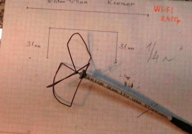
Let's start with a copper tube. We cut one end by 1.5 mm, removing two thirds of the wall. An antenna will be soldered to the remaining piece. Create a biquadratic contour from the wire with a side of 30.5 mm. The size is selected from the condition for setting the 2.4 GHz band.

Likewise, any horizontal or vertical polarization signal antenna can be fabricated. Including television. A homemade Wi-Fi antenna is suitable for a tablet, phone, modem. If you know where to connect.
Please note that the side of the squares is given according to the middle section of the wire. Between the nearest edges there will be 30.5 - 1.2 = 29.3 mm. You can use it. We begin to bend, finding the middle. We use the edge of the ruler as a support, we determine the state when the cut begins to balance. We make a bend by 90 degrees, this will be the point where the central core of the RK-50 will connect. We bend the wire, getting a "square eight", both ends must return strictly symmetrically. We cut it off, a couple of millimeters before the initial bend. Tinkering the ends, put the figure eight aside.
We mark the middle of the PCB, drill a hole so that the copper tube barely fits. We play both sides. We take a copper tube, tin the outer edge of the thin wall left by the first step. The figure eight is 1.5 cm from the reflector. We lud the tube in a circle, with a rim at a specified distance from the edge (excluding the thin wall). We solder the tube to the board, preferably at a 90 degree angle. We put both ends of the figure eight on a thin wall so that the initial bend does not touch the tube. We orient the eights parallel to the larger side of the PCB at a distance of 1.5 cm. The reflector is now grounded.
The RK-50 cable is pulled inward, the screen is mounted on a copper tube, and the core is placed on the initial bend of the figure eight. We mount the connector on the opposite end, just solder the cut to the right contacts modem, telephone, any other device. We start the test. Figure 8 must be set vertically for horizontal polarization. If it works, we find a silicone sealant that is not afraid of frost, precipitation, fill the place where the cable exits to the antenna with a good layer. Once solidified, the antenna will successfully withstand rain.
If we replace the wire with a thick conductor PV1 of a sufficiently large cross-section (2.5 mm 2), we will clean the braid at the point of the initial bend and at the ends. Homemade laptop Wi-Fi antenna will be weatherproof. Today shrink materials are produced. The heated film tightly wraps the product, protecting it from the vagaries of bad weather.
Transform the antenna regular WiFi router into an improved one, which will have a greater range, and all this can be done in 15 minutes at no cost.
Very often, a narrow-band whip antenna is used for inexpensive WiFi routers. In fact, it is just a piece of wire. In expensive routers, there is already a longer antenna with matching turns. Naturally, such an antenna catches many times better. I have used at home cheap model router, for which I will make a good antenna, like expensive models.
And so, let's get started ...
Remove the top of the plastic from the antenna.
A small screwdriver is perfect for this.
It is necessary to repeat the shape of the improved antenna, as shown in the photo.

You will need: a small insulated or bare copper wire, a wood screw, a measuring tape and a soldering iron

Measure 7 cm of the wire and make a bend in this place

Using the screw as a template, wind a full seven turns of wire around the screw, starting from the marked location. To remove the screw, turn it counterclockwise.
Cut the wire 2 cm below the resulting spring.

After that, you need to strip 3 mm of insulation or strip 3 mm of bare wire (depending on which one you are using).

Cut the standard antenna wire, leaving approximately 6mm
Then remove 3 mm of insulation.
Solder the new antenna to the remainder of the wire.

To do this, you need to lay bare parts of the wires.

Take a large cocktail straw and slide it over the antenna.
For example, these are used in McDonald's.
The straw should be perfect for the base of the WiFi antenna as well.
You won't even be able to glue them together. It looks like it was intended that way.
To keep the straw from sticking out, you can paint it with a permanent marker.
Manufacturing.
First of all, you need to make a reflector - this is a metal sheet 450x350 mm ( rear part antennas). It serves to reflect and wifi transmission waves on the vibrators and also serves as the body of the antenna itself.
To do this, take a fairly thick sheet of iron. For example, the body from the old washing machine or a baking sheet will do the job. Cut out the desired size with a "grinder" and clean it from rust. see photo 1 on the right
Postpone while aside the blank of the reflector and we will be engaged in the manufacture of vibrators, which will be located on a one-sided 1.5mm fiberglass. To do this, you need to purchase a vinyl stencil of vibrators with a self-adhesive mounting film. Such things are done in plotter cutting workshops according to the provided drawing.
Download Delta Ds 2400-21 drawing. Copy to usb flash drive... At the plotter cutting company, explain to the manager what the actual dimensions of the parts of the drawing should be!
Before gluing the stencil, remove small scratches and polish the copper surface of the fiberglass with zero and GOI paste. Degrease with solvent (acetone), surface! Carefully transfer the stencil onto the copper surface of the fiberglass. Let's start etching the antenna circuit board.
Pour hot water in a container of a suitable size, add copper sulphate and edible salt in a ratio of 1: 3, mix well and lower the glass fiber laminate down with copper. To prevent the board from sinking, first use double-sided tape to glue the foam on the opposite side. Wait for the excess copper to completely dissolve. see photo 2 on the left.
When the process is over, rinse the fiberglass with clean water, remove the vinyl from the vibrators and tracks. Punch a hole for the N-235 TGT connector pin and tin. For protection from the external environment and from oxidation, cover the side of the antenna with the vibrators with insulating varnish!
Apply fiberglass to the reflector, mark and drill a hole for the n-type connector. Same way make holes for outdoor wifi antenna mount kit, see photo 3 on the right.
Next, we need to connect the reflector and the fiberglass board together. The gap between the reflector and the vibrators must be 9mm.!
Here's how we proceed - glue the 6mm floor laminate to the reflector with a THIN layer of glue. Before that, place them evenly on fiberglass using double-sided tape, see photo 4 on the left.
Laminate 6 mm + fiberglass 1.5 mm + adhesive 1.5 mm = 9 mm gap.
Now place and tighten the N-235 TGT connector. After the glue dries, we detach (holding on to double-sided tape) fiberglass from the reflector. We close the laminate and the connector with masking tape, and paint the reflector on both sides with metal paint for outdoor use. The reflector is almost ready, we attach the structure of the external antenna mount.
Next, we apply a thin layer of "moment" glue to the laminate and connect the reflector with fiberglass. Having inserted the contact of the n-type connector into the hole, we solder its tip to the copper track of the vibrators. See photo 5 on the right.
V this example No protective cover for the antenna is provided. Instead, a hybrid adhesive sealant "Soudal Fix All Crystal" is used and is applied around the perimeter between the reflector and the fiberglass, See photo 6 on the left... Then the front of the wi-fi antenna is covered with three layers of white, acrylic paint. Check the paint first to see if it will shield your antenna. Paint on a piece of thick paper and when the paint is completely dry, cover the front of the wi-fi antenna. If the signal does not change, feel free to use this paint. See photo 7 on the right.
Let's check this product in action.
Here are the results of testing a DIY Wi-Fi antenna:
In order to connect the antenna, we need an external USB wifi adapter... This example uses "alfa awus036h 1000mw - Taiwan".
First, connect the adapter, without an antenna, and see what it shows us, and will it work at all? As it turned out, alfa found three points. We will focus on the connected point -66 dBm. For half an hour, the signal remained almost unchanged, and this was without any antenna. See photo 8 on the left.
Now, without changing the location, let's check our homemade Wi-Fi antenna by pointing it towards the router. As you can see, the result is dramatically different for the better. See photo 9 on the right... The signal of the connected point has improved from -66 dBm to -45 dBm. Three more points were found.
66-45=21.
It turns out that the antenna gain is 21 dB.
WiFi antenna- an excellent solution for everyone who tried to organize wireless distribution of the Internet at home or at work, but faced such a problem that the signal of the router is not enough to use it without problems in some remote room. However, this is not your router's fault at all, but the antenna - built-in or external, which was included in the package. One of the most effective amplification solutions wireless signal — directed external wifi antenna. They come in several types and types, which are used depending on your needs. And it is precisely in this diversity that we are now going to understand.
First of all, it should be noted that a passive antenna for wifi router, that is, which does not have its own power supply from the mains, does not amplify the signal, but only directs its spectrum for more confident reception. The power of this "gain", which is also called the gain, is measured in decibels (dBi). Many models of routers and adapters are already equipped with small external antennas, but their power does not exceed 3-5 dBi, which will not significantly improve the range of the wireless signal.
Therefore, external wifi antennas are used for this. They have two types of separation - for outdoor or indoor use, as well as omni-directional and narrow-directional.
Outdoor and indoor antenna use
- Outdoor antennas are those designed for outdoor use. They are protected from the effects of precipitation and sunlight and special mounts for installation on the wall of the building. You will need them if you want to create a secure reception area in the yard or for communication between neighboring houses.
- Internal antennas- for indoor use. For example, if your router is installed in a remote or closed place, then such an antenna can be connected with a cable to the antenna connector of the router and brought to the center of the room.
Directional wifi antenna
This is the most commonly used type. Antenna, guide wifi signal in a certain direction, for example, from a house to a personal plot, or to the balcony of a neighboring house, if we are talking about an external directional wireless antenna. The range of their action can be from one to several kilometers. The main thing is that the source of reception is in line of sight.

Internal directional wifi antennas for the router will be useful if, for example, it hangs on a wall. To prevent radiation from going through the wall, you can connect it to the router and direct it towards your desktop, on which there is a laptop. Or, conversely, direct the antenna towards the partition so that the signal passes through it more confidently, ensuring stable communication in the next room. A very successful design of such an antenna is a panel rectangle that emits a radio signal in one direction.

Please note that it is connected to the router not via USB, but instead of the attached antenna that came with the router. Accordingly, if it was not removable, then it will not work to put another instead of it.
There are also compact models that are suitable for both indoor and outdoor use.

Omnidirectional wifi antenna differs in that it evenly distributes the signal around itself. The disadvantage is that the signal can be distorted by radiation from other electronic devices in the apartment, or by external radio waves if it is installed outside. Such antennas look like a vertical rod. External can be installed on the roof of the house or on a vertical pole dug into the ground. Internal - on a table or shelf, as close as possible to the intended center of the desired reception area.

An external wifi antenna for a router is also attached to the place of a standard one to the same connector.

Another interesting type of indoor omnidirectional wifi antenna is for ceiling mounting. They look like a lamp. Its peculiarity is that there is a dead zone right under the antenna and you need to hang it exactly in the place where the signal is not needed, and confident reception will begin only at a short distance from it.
Installing a WiFi antenna
When installing any type of antenna, it is necessary to consider where the signal source comes from. In the conditions of modern urban development, it can very much lose in efficiency both because of the density of houses and because of the materials from which they are made. I give a table from which you can roughly understand how much this or that material worsens the operation of the access point. The most important parameter here will be "Effective distance" (ED). It should be calculated as follows. For example, the characteristics of the router indicate that it works at 400 meters. it is assumed that with a line of sight. You are separated from it by an interior wall, in which the ER is 15%. We calculate: we multiply 400 m by 15% and we get 60 meters. That is, the router will "shoot" only 60 meters through a wall of 15-20 cm. Moreover, if you connect an antenna of 15-20 decibels to it, then this loss is neutralized.
Homemade wifi antenna do it yourself
You can make a directional Wi-Fi antenna with your own hands. Watch the video on how to make a homemade design from a regular beer can.
I can't say for sure if this is true or false - I think there is some reason. By analogy with this popular example, you can also make a directional antenna from an omnidirectional one. To do this, it is enough to attach a reflective screen behind it, for example, from the same sheet of foil. Below are some interesting options for making an antenna with your own hands, which you can use.
 Option with a tin can as a reflector


That's all for today. You can read about ways to amplify the signal of a 3G modem in another blog article.
We decided to make an antenna for WiFi ... There are many options, netizens are looking for new ways. Probably because there are a myriad of situations in life, each decision is powerless to lay out the network. Today we propose to consider a couple of methods for improving reception / transmission. Atypical solutions will be considered, the design process of Kharchenko's antenna has been described many times. According to the designer's idea, dated the 70s of the last century, in a modernized version. Would you like to make a WiFi antenna yourself? Better read the review further! Let's get started.
Increase the gain of the WiFi antenna
With the help of beer cans, you will assemble an antenna for receiving the MV range (the ubiquitous First Channel), an excellent reflector of an arbitrary frequency. A parabolic surface has one interesting property:
Beams coming from any direction are reflected and collected by the focal plane. If you aim the product at the broadcasting point, the lines will intersect in focus.
The Internet was flooded with improvements to factory modems, antennas in order to obtain additional amplification. Without paying a penny. Consider saving techniques. Majority external antennas WiFi omnidirectional modems. In the factory modem, antennas 2-3 (often inside) can be divided as follows:
- The presence of an external / internal antenna.
- The presence of several internal antennas.
- Multiple outdoor antennas.
It is clear that most modems are standard, the uninitiated ask the question: what does the number of antennas give? The answer is simple: better reception and transmission. The communication adopted vertical polarization. The vector rotates, the signal disappears altogether. An antenna with circular polarization will correct the matter, it will receive no worse, it will not fall into dependence on the direction of the electric field.
Homemade antenna
Today there are two surfaces of interest:
- A paraboloid of revolution is obtained if the ordinary graph Y = X 2 is rotated around the axis of symmetry (in this case, the ordinate). The rays coming from the side of the concave part will be collected by the focal plane. Using the principle, satellite dishes work. If you take a ready-made, arbitrary radius, make something similar with your own hands from paper, epoxy resin, foil, you get an efficient device for enhancing reception.
- In the case of whip antennas, a fold surface can be used. A purchased sheet of thin steel is adjusted according to the pattern - let's talk below. The method is widely discussed on the Internet, a semicircle is used instead of a parabola, tin is taken from a beer can. We see a minus: the two lines coincide approximately at the very beginning of the abscissa axis. Accurate focusing is not possible and the gain drops.
Let's see why the WiFi antenna starts to receive better when fenced off with a reflector. In a YouTube video, ValeraZik says: some of the pins, being covered from one side with the palm, receive better (any channel), part of the radiation is reflected by the hand. Not true. If you take the master of kung fu (the path of the blocking fist), the hand will be like a steel hand, the hand of other people, as well as a shuitsa, is unable to reflect anything.
The hand extinguishes radiation coming from other directions. Artificial interference, natural sources. As a result, the quality of the signal increases inexorably. Sometimes noticeable with the naked ear, in the case of long antennas it may not play a role.
Let's imagine using the example of human hearing. Lor is quietly talking numbers, we try to hear, they are constantly chatting at the other end of the room. Let's say they fenced off from interference with a partition, a sound insulator wall, of course, necessary information will be perceived more clearly. If the hand is replaced with a grounded metal shield, the situation will change radically. The wall reflects the excess waves back, useful information will concentrate at the desired point. Of course, if you choose the correct shape envelope.
Using a parabolic WiFi transmit / receive antenna
It happens that the points of broadcasting, receiving in line of sight, are significantly removed. Firstly, factory, home-made log-periodic antennas, wave channels will come in handy, they act witty too. WiFi at 5 GHz coincides with the frequency of the satellite broadcasting range C. There is a topic at forumru.tele-satinfo.ru/index.php?topic=70121.0, it is shown how to convert the converter from receiving to transmitting a signal. Of course, the experiment is not for beginners, but, having received a successful alignment, we catch the broadcasting of space, all the more we will accept it from the Earth.

Now let's remember that it is the C range that is less afraid of fogs, rains, and other whims of nature. It is necessary to organize a bidirectional channel. There is a lot about the receiving part, it is written in detail here cqham.ru/ao40_equip.htm. It is proposed to subordinate the MMDS converters to the fishing goals (cable broadcasting on the air, there is no way to lay the network underground, on the surface). The difference with WiFi in the range is 100 MHz, the author at the specified link discusses how to properly convert MMDS converters to WiFi. In more detail, a slightly different problem is being solved, for our case the solution is suitable (in the review, the author is trying to establish a connection at the WiFi frequency with the AO-40 radio amateur satellite).
The topic of a bidirectional channel is discussed. A helical antenna is used for transmission, the construction of which (with your own hands) was discussed in the section. Equally are the nuances of the directional diagram of the device. From the text of the article it can be seen: the factory plate is suitable for the purposes of reception. Suitable for complementing the functionality of the already standing one (NTV +). Discussed how to properly adapt WiFi equipment. Let us briefly recall that there is no need to touch the plate itself, just, based on the laws of optics (the angle of incidence is equal to the angle of reflection), estimate at what point of the focal plane will be WiFi modem, antenna.
Mini antenna with reflector
A swarm of converters stuck around the multifeed, add a receiver there. The orbit is projected onto the focal plane along one large diameter arc, location point better reception WiFi depends on the coordinates of the transmitter, relative to the dish.
We understand that links to forums are not able to act as a reliable source. First, readers can search Yandex for how to do it correctly. technological operations secondly, they can ask the administrator to post a topic. Then we will do the work. We hope the readers understood, understood the possibility of using satellite equipment for terrestrial communications (MMDS).
Make a beer can screen for a WiFi antenna
Sometimes making an antenna for WiFi with your own hands is not the best option, it's easier to re-equip an existing one. Consider a common case of limiting the broadcast area of an access point. If you cover some antennas WiFi hand, the quality of reception will improve, you will not sit all year round! For those who want to solve the problem, we give the name of the program - Inssider. A signal level meter with which you can find the best antenna, create a suitable screen, aim the device in azimuth. Actually, start with this, then design / buy.
ZikValera in the video demonstrates a comparison of antennas, factory and own assembly. Those who want to spend 20 minutes on contemplation are sent to watch, and we bring the rest: the directional biquadrat, the non-directional “clover” with versatile polarization, shows itself better. The best factory model can be appreciated. But it's not about making a directional WiFi antenna. We want to show you how simple methods improve the available ones.
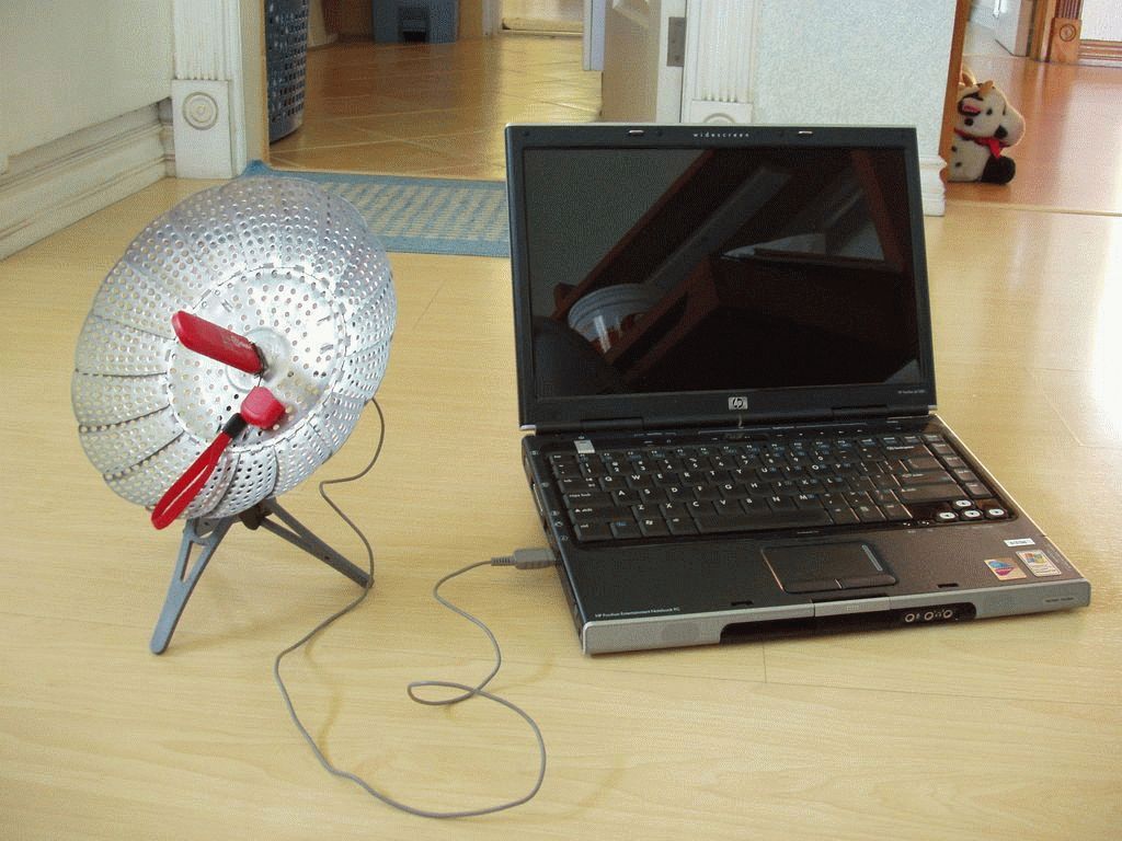
How to make an antenna for WiFi yourself, modify it to improve the quality. Make a beer screen from a can, put the pin in focus. It is easier to do, if you are too lazy to write out the equation of an ellipse from analytical geometry, place the antenna in the focus of the figure. ZikValera tried to do it optically by eye. I considered the focus to be the position at which the antenna's reflection "spreads out" to the maximum along the inside of the can. The authors presented a scientific approach. Let us add that during visual assessment it is necessary to look from afar - so that the lines of sight are parallel to each other - this is how the wave front behaves in real reception. So you can make the omnidirectional WiFi antenna directional, at the same time raise the gain.
Any antediluvian equipment turns into the right one with a skillful approach. It's funny to see landfills littered with plastic window frames. The picture shows the inability of society to fully use resources.