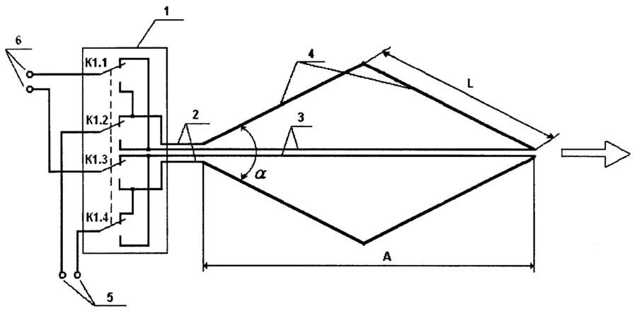
72) Authors of the Invention of the All Union for PATENT TECHNOLOGIES a video-plane reflective surface, for example, a rectangular configuration 1). The disadvantage of known passive retranslators is the relatively strong bond stability at linearity and the change in refraction conditions. A change in refraction conditions is equivalent to a change in the angular orientation of the repeater's radiation pattern. For large (in the electrical sense) repeaters, real changes in the refraction conditions can lead (and lead) to the fact that the repeater's orientation pattern on the active station is oriented at a low signal level or even zero, which leads to a link failure, The use of smaller repeaters (which is equivalent to the expansion of the repeater's radiation pattern) reduces the probability of zero orientation diag The intensity of the repeater is reduced, which also leads to a decrease in the stability of communication. The aim of the invention is to increase the stability of communication when the refraction conditions change, as well as the deformations of the passive retranslation due to thermal and wind effects. This goal is achieved by passive the repeater is made from three parts - central and two symmetrically located lateral parts, all of the passive repeater are executed by hyosky , Wherein tsentralnayachast has a rectangular shape relative to the side ivystupaet chaste3. 96480 by an amount equal to -COEO where LVW is the wavelength, and 6 is the angle of incidence of the wave on the passive repeater, measured from the normal to its surface, the area of the central part of the passive repeater is 10-204 from, the entire area of the passive repeater, and the larger side of the rectangular part is placed horizontally. In FIG. d schematically depicted; 10 passive repeater; in fig. 2 is a radio link, containing a passive repeater in FIG. 3 - directional diagrams of the repeater, 15 explaining the essence of the proposed technical solution. The passive repeater contains flat central 2 and two side parts 3 symmetrically located with respect to it, the central 20 part 2 being rectangular and projecting relative to the side 6, where 7 is the wavelength, 6 is the angle of incidence 5 of the wave emitted by the active station 6 and received by the active station 7, measured from the normal 8 to the surface of the passive repeater. The area of the central part 2 is 10–20 / of the total area of the passive repeater, and the large side 9 of the rectangle of the central part 2 is horizontal in space. 35 The proposed design of a passive repeater leads to a change in its directional properties, namely, the “swimming” of zeroes.40 The directional diagram of the known and proposed passive retransmitters is shown in FIG. 3 (curves 10 and 10, respectively). As can be seen from the curves, when the condition of refraction changes (which is equivalent to a change in the generalized angular coordinate H, which takes, for example, the values of nd 2, 13 and 14) 2 4 the gain is much smaller for the passive repeater, than for the known repeater. Thus, a change in refraction conditions significantly affects the stability of the radio link as a whole. The use of the proposed technical solution is particularly advantageous on radio links with passive repeaters that have long between active stations. The use of the invention makes it possible to increase the stability of communication on existing radio relay lines with passive repeaters of the reflecting type; increase the distance between active stations without a significant deterioration in the quality of communication. Invention formula: Passive repeater containing a reflective surface of rectangular shape, which is so that, in order to increase the stability of communication when the refraction conditions change, the passive repeater is made of flat central and two symmetrically located lateral parts, and the central part is made rectangular and protruding relative to the lateral parts to a height equal to - cos 8, where L8 is the wavelength ,. 9 - the angle of incidence of the wave on the passive repeater, which is cut off from the normal, the area of the central part is 10-203 of the entire area of the passive repeater, and the large side of the rectangle of the central part is placed horizontally. Sources of information taken into account during the examinations. Eisenberg, G.Z. Yampolsky VG, Passive repeaters for radio-relay lines, And "Communication, 1973, p., 13-14.
5.7. PASSIVE REPEATERS
There are such conditions when reliable reception of television programs is impossible due to an excessively low level of field strength at the receiving point. This may be due to the large distance to the television transmitter, but sometimes the reason is that the terrain is unfavorable and the receiving point is located in a hollow. In this case, the direct passage of the signal prevents the presence of a hill or mountain barriers. In such circumstances, resort to the use of active or passive repeater.
An active repeater is a combination of a receiving antenna, a radio receiver of a complete television signal, a frequency spectrum converter, a radio transmitter of the transformed signal, and a transmitting antenna. A frequency spectrum converter is required so that the signal is transmitted by the repeater on a different frequency channel relative to the channel on which the signal was received. This is required to eliminate interference for those TVs that may fall into the zone where both the main signal and the retransmitted signal can be received. In the early years of the development of mass television, when the number of television centers was small, some amateur radio groups created active repeaters to ensure the possibility of confident reception of television programs in their village. Currently operating network
television centers and state active repeaters have become so thick that it is sometimes impossible to choose a free channel number that does not interfere with the signals of surrounding transmitters. Therefore, the bodies of the Ministry of Communications strictly forbade the construction of amateur active repeaters. Installation of the state active repeaters is performed according to the plan, taking into account the transmitters already operating in each region and their frequency bands. At the same time, in order to install a new repeater, it is necessary to change the channel numbers of existing television centers and repeaters.
Passive repeater differs in that it does not contain transceiver or amplifying equipment, and reception and transmission are carried out exclusively by antenna systems.
There are three types of passive repeaters: refracting, reflective and obstacles.
A refractive type repeater in the simplest case is a combination of two highly directional antennas, one of which is oriented on the transmitter antenna, and the second is directed to the receiving point. Thus, the signal is reradiated in the right direction.
The reflective type repeater is made in the form of one or two flat antenna mirrors, which provide a change in the direction of propagation of the signal. The antennas of the repeaters of the refracting and reflecting types must be made with high accuracy of the working surfaces with large sizes of the canvases of these antennas, reaching hundreds of square meters in the television frequency range. In addition, the rigid fixation of the working surfaces of the antennas in space should be ensured, which requires the use of super-rigid supports. Therefore, repeaters of the refracting and reflecting types have recently rarely been used on state communication lines and are completely unacceptable in amateur radio conditions for receiving television programs.
A passive obstacle-type repeater was proposed in 1954. G. 3. Eisenberg and AM Model. Such a repeater is a metal surface located between the transmitter and the receiver, located relative to the transmitter in the shadow zone (Fig. 5. 13). In the absence of a repeater, a transmitter antenna installed at point A practically does not create an electromagnetic field at point B because the point of reception is shaded. When an obstacle is placed in the propagation path of a signal at point B, a field appears at point B This is due to the fact that
Fig. 5. 13. To the explanation of the installation of a passive repeater
an obstacle in accordance with the principle of Huygens is excited by a wave incident on it and becomes a source of secondary radiation. With an appropriate choice of the shape and size of the obstacle, the field strength at point B may be significant and sufficient for reliable reception of a television signal. The role of the obstacle is that on the signal propagation path a surface with zero field strength is formed on the side that faces the receiving point.
Deformations of the working surface of the repeater of the obstacle type caused by the wind or its deviations due to manufacturing inaccuracy do not affect the intensity of the radiation and the level of field strength at the receiving point. This is the main advantage of repeaters of the type of obstacle over repeaters of the refracting and reflecting types. Therefore, an obstacle-type repeater web can be made not in the form of a rigid metal structure, but in the form of a wire mesh, but the rigidity of the frame structure of such a mesh is determined solely by the necessary mechanical strength. There is also no need to adjust the working surface of the repeater after its installation, which is mandatory for repeaters of refracting and reflecting types. All this indicates that passive type of obstacle repeaters can be widely used for reliable reception of television programs in difficult relief conditions when installed by radio amateurs.
The optimal web form of the repeater of the obstacle type is arcuate. However, practically due to the fact that the horizontal dimensions of the web are much less than the distance to the relayed transmitter, the arc degenerates into a straight line, and the same results are obtained by a rectangular web. The cloth of the repeater is installed in a vertical plane, perpendicular to the line connecting the points A and B. The installation of the cloth of the repeater on the supports is shown in fig. 5. 14. The maximum height of the canvas is equal to the height of the Fresnel zone and can be determined by the formula
The maximum width of the canvas is determined by the permissible dephasing of fields emitted by the middle and edges of the canvas:
Fig. 5. 14. Cloth Passive Repeater
In these formulas, L - wavelength of the received television channel, but -the angle between the directions of the field incident on the web and the radiated field on the receiving point, R2 is the inclined distance between the repeater web and the receiving antenna. The formulas are valid when the distance between the transmitting antenna and the repeater is significantly greater than the distance between the repeater and the receiving antenna. Otherwise, instead of R2, the value R1R2 / (R1 + R2) should be substituted into the formula. The dimensions of the canvas are obtained in meters, if distances are also expressed in meters.
When calculating the size of a passive repeater, it should be noted that the resulting dimensions are the maximum allowable: an increase in these dimensions leads to a decrease in the effectiveness of the repeater. In fact, in the ranges of I and II meter waves, these dimensions can be really unfeasible. We give the following example. Suppose the distance from the transmitter to the transponder R1 = 30 km, the distance from the repeater to the receiving antenna R2 = 1 km, and the angle between these directions is a = 10 °. Then for the first television channel with a wavelength of L = 6 m, the maximum web height will be 17.3 m, and the maximum web width is 132 m. In such conditions, the web can be made smaller, although the repeater efficiency, which is proportional to the surface area of the web, will decrease . For the same conditions, if transmissions are received on channel 12 with a wavelength of 1.32 meters, the size of the canvas is closer to reality: height -3, 7 m, width - 61, 3 m. Finally, for the 33rd the channel of the decimeter wavelength range at a wavelength of 0. 53 m; the dimensions of the web are even smaller: height - 1, 5 m, and width - 39, 1 m.
The effectiveness of a passive repeater of an obstacle type can be characterized by the ratio of the field strength at the location of the repeater to the field strength at the reception point:
field strength at the receiving point will be 5, 3; 11, 2 and 18 times less than the field strength at the point of installation of the repeater for the 1, 12 and 33rd channels, respectively.
From the transformed formula, it can be seen that at small angles and the field strength at the receiving point is inversely proportional to this angle, and its dependence on the distance to the repeater and on the wavelength is weaker,
since their values are included in the formula under the sign of the radical, if the size of the canvas is chosen as the maximum allowable. In the same time maximum sizes the webs depend on the wavelength, they also decrease with decreasing wavelength, especially the height of the web, which depends from wavelength in the first degree. Thus, the effectiveness of the repeater with decreasing wavelength could be increased if it were possible to increase the size of the canvas in excess of the maximum allowed. This turns out to be possible if the canvas is made not solid, but consisting of several horizontal strips overlapping the Fresnel zones through one, i.e., one sign. Due to the fact that in the decimeter wave bands the maximum allowable web height is small, a web of two or three bands can be made, with the height of each band and the distance between them in height being equal to the found value of the maximum web height. Such repeaters are called multi-element.
The effectiveness of a multi-element obstacle-type repeater increases in proportion to the square of the number of bands. Thus, if in the example shown, the repeater web for the 33rd channel consists of three lanes of 1.5 m each, with the distance between them in height also 1.5 m, the efficiency of the repeater will increase 9 times. In this case, the field strength at the receiving point will no longer be 18 times less than the field strength at the point of the repeater installation, but only twice.
On flat terrain with a large length of the route, the use of amateur radio passive repeaters like an obstacle becomes unrealistic for the following reasons. Installation of the repeater should be done at a point in the route where the field strength is high enough, and this point is usually located tens of kilometers from the reception point. With the increase of this distance, the efficiency of the repeater decreases with an equal effective web surface. The angle between the directions of the field incident on the repeater and radiated to the receiving point decreases to fractions of a degree, which leads to an increase in the maximum allowable web height. At the same time, the installation of a multi-element repeater, even for the UHF range, becomes unrealistic due to the fact that, under such conditions, repeaters have an unacceptably large height of each band and distances between them.
It is advisable to install passive obstacle repeaters in conditions where the reception point is closed in the direction of the transmitter by a nearby high obstacle, and on top of this obstacle, on which the repeater will be installed, the signal field strength is sufficiently large. Then the repeater canvas can perform the maximum allowable size even for the first television channel, and for the 12th channel the repeater can be made multi-element.
Consider now the practical execution of the canvas repeater. The theory of passive repeaters is based on the assumption that the obstacle is a solid metal sheet. However, in practice, the web is made in the form of wire mesh. Such grids well reflect electromagnetic waves, if the polarization of the incident field is parallel to the wires of the grid. Then, when the signal is horizontally polarized, the web should be made in the form of horizontal wires, and when vertical
polarization - vertical. The distance between the wires must be significantly less than the working wavelength. It can be considered sufficient if their ratio is at least 20. The diameter of the wires also matters: the larger the diameter of the wires, the lower the seepage power and the better the web. Good results in the manufacture of web repeater gives an antenna cable. To ensure the strength of the wire, webs can be sealed with transverse wires of any diameter, showing all points of intersection. The distances between the transverse wires are chosen arbitrarily for reasons of mechanical strength. The canvas of the repeater is installed on two or more supports. If intermediate supports are used, all parts of the web should be in the same plane. The rectangular shape of the canvas is provided by its suspension to the kapron cord. Isolating the canvas from the supports is not necessary. The height of the lower edge of the web above the ground must be at least several wavelengths of the received channel.
When using a passive repeater, the receiving antenna must be oriented in the direction of its canvas, not only in azimuth, but also in elevation. Therefore, the geometric axis of the antenna is not horizontal, as usual, but must be located at an appropriate angle to the horizon.
Signal amplifier mobile communications solves the problem of telephone calls and the Internet in the country, in the garage, as well as in other hard-to-reach areas. This support equipment is not cheap. The problem will solve the gsm repeater, made by own hands, which will completely replace not the most powerful commercially used repeater.
Repeater is passive and active. The first does not require a power connection and is an antenna capable of operating independently in a small area. It is also used as part of a system with an amplifier that is connected to the mains.
Passive repeater LTE or GSM standard catches weakest signals corresponding frequency ranges and transfers them to devices. This is the simplest option for self-production from scrap items and materials. The minus is the lack of amplification and stabilization of mobile communications.
GSM repeater cellular communication, made by hand, operates without connecting to the gadget.
Amplifier circuit cellular signal includes:
- power divider or wire splitter (if several points are needed to amplify the signal);
- power connectors;
- coaxial cable for connecting the antenna.
The system allows to improve the quality through the use of multiple antennas. Also on sale are passive amplifiers, connect directly to the phone with a cable. In addition to the high price, the very fact of having wires hampers freedom of movement during calls, and the quality of communication gets worse with each additional meter of wire.
GSM repeater do-it-yourself video:
DIY antennas
To make your passive repeater suitable conventional wire or even a can. From the first you can make an antenna from the rings or in the form of a double rhombus.
Antenna or repeater gsm signal from wire.
The sizes are determined by the required frequency, for example, take F = 900 MHz. The diameter is calculated by the formula (300 / F) / 3.14, that is (300/900) / 3.14 = 0.106 m. This coil is the antenna.

Antenna from one ring
Interconnected: they differ from the first variant by two turns of wire instead of one, the construction is carried out from one segment. We fix them opposite each other. The distance is calculated according to the formula (300 / F) / 4, for the case in question it is (300/900) / 4 = 0.08 m. The same frequency is given, the diameters are calculated similarly.

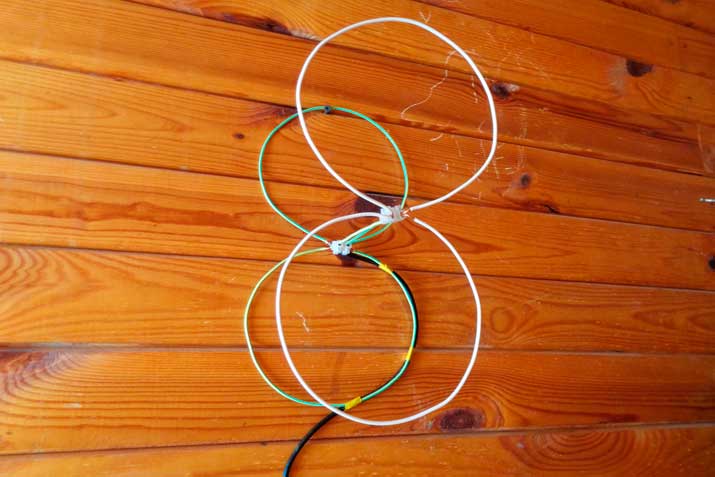
GSM antenna of two rings
Four rings: The antenna is similar to the second, only instead of turns there will be two eights. The calculation is similar to the previous paragraphs.
Diamond Amplifier: The wire is bent in a square shape, then two opposite corners are bent to each other and sealed. For clarity, the scheme gsm repeater:
GSM Amplifier Diagram Amplifier Cellular Signal Circuit
A full-fledged homemade gsm repeater will require, in addition to the antenna, a cable, fasteners (for installation), a length of 20 cm of a polymer pipe or a plastic jar (as a connecting unit), a plastic sheet, a screen (reflective material), 2 straws.
How to make a gsm repeater with your own hands:
- to build a diamond-shaped antenna according to the above instructions;
- on the pipe cut, make four cuts of about 3 cm in length. The received connecting block is put on the antenna angles bent inwards;
- if a can is used, then make three holes in the bottom - central for two straws, two extreme for screws;
- attach one wire to the two curved corners. Remove the wires, for example, by taking a piece of cable and removing an insulating film from it;
Send your good work in the knowledge base is simple. Use the form below.
Students, graduate students, young scientists who use the knowledge base in their studies and work will be very grateful to you.
Posted at http://www.allbest.ru/
Introduction
Different media are used to transmit telecommunication signals: electric or optical communication cable, airspace, etc. In this case, regardless of the chosen method of transmission, the initial energy of the signal, which was at the output of the transmitter, will decrease. In other words, the signal will fade out.
The main negative consequence of this process will be the difficulty in receiving the signal, i.e. if the energy of the signals at the output of the communication channel is less than a certain level (sensitivity threshold of the receiver), then the signal may be received with an error.
The main cause of this problem is the geography of the earth, as well as artificial objects. For example, a wall in a residential house introduces a very perceptible attenuation, as a result of which there may not be any in the center of the communication building. It is necessary to redirect the electromagnetic signal to the "shadow" zones where there is no connection.
One way to solve this problem is to install passive receiving and transmitting stations, the so-called passive repeaters.
1. The principle of the repeaters
A repeater is a set of equipment designed to provide communication between two or more radio transmitters, remote friend from a friend over long distances.
There are such conditions when reliable signal reception is impossible due to an excessively low level of field strength at the receiving point. This may be due to the large distance to the transmitter, but sometimes the reason is that the terrain is unfavorable and the receiving point is located in a hollow. In this case, the direct passage of the signal prevents the presence of a hill or mountain barriers. In such circumstances, resort to the use of active or passive repeater.
An active repeater is a combination of a receiving antenna, a radio receiver of a complete television signal, a frequency spectrum converter, a radio transmitter of the transformed signal, and a transmitting antenna. A frequency spectrum converter is required so that the signal is transmitted by the repeater on a different frequency channel relative to the channel on which the signal was received. At present, the network of existing communication channels and state active repeaters has become so thick that it is sometimes impossible to choose a free channel number that does not interfere with the signals of surrounding transmitters.
Passive repeater differs in that it does not contain transceiver or amplifying equipment, and reception and transmission are carried out exclusively by antenna systems.
There are three types of passive repeaters: refracting, reflective and obstacles.
A refractive type repeater in the simplest case is a combination of two highly directional antennas, one of which is oriented on the transmitter antenna, and the second is directed to the receiving point. Thus, the signal is reradiated in the right direction.
The reflective type repeater is made in the form of one or two flat antenna mirrors, which provide a change in the direction of propagation of the signal.
A passive obstacle-type repeater was proposed in 1954 by Eisenberg and A.M. The model. Such a repeater is a metal surface located between the transmitter and the receiver, located relative to the transmitter in the shadow zone. In the absence of a repeater, a transmitter antenna installed at point A practically does not create an electromagnetic field at point B because the point of reception is shaded. When an obstacle is placed in the propagation path of a signal at point B, a field appears at point B This is due to the fact that the obstacle, in accordance with the principle of Huygens, is excited by the wave incident on it and becomes a source of secondary radiation. With an appropriate choice of the shape and size of the obstacle, the field strength at point B may be significant and sufficient for reliable reception of a television signal. The role of the obstacle is that on the signal propagation path a surface with zero field strength is formed on the side that faces the receiving point.
Deformations of the working surface of the repeater of the obstacle type caused by the wind or its deviations due to manufacturing inaccuracy do not affect the intensity of the radiation and the level of field strength at the receiving point. This is the main advantage of repeaters of the type of obstacle over repeaters of the refracting and reflecting types. Therefore, an obstacle-type repeater web can be made not in the form of a rigid metal structure, but in the form of a wire mesh, but the rigidity of the frame structure of such a mesh is determined solely by the necessary mechanical strength. There is also no need to adjust the working surface of the repeater after its installation, which is mandatory for repeaters of refracting and reflecting types.
Figure 1.1 - To the explanation of the installation of a passive repeater
Passive type of obstacle repeaters should be installed in conditions when the receiving point is closed in the direction of the transmitter near a high obstacle, and at the top of this barrier, where the repeater will be installed, the signal field strength is sufficiently high.
When using a passive repeater, the receiving antenna must be oriented in the direction of its canvas, not only in azimuth, but also in elevation. Therefore, the geometric axis of the antenna is not horizontal, as usual, but must be located at an appropriate angle to the horizon.
1.1 Passive repeater using two antennas
In this paper we will consider a passive repeater consisting of a receiving (external) and transmitting (internal antenna), which are connected with a cable. The repeater is illustrated by the following diagram - figure 1.2.
Figure 1.2 - Passive repeater with two antennas
The signal is received by an external antenna with a sufficiently high gain, then transmitted via cable to an internal antenna installed in the room, which will provide access to the network for various devices. The use of this type of repeater is advisable only if the signal level in the room does not meet the needs of users.
2. Antenna selection
Receiving antennas convert the energy of electromagnetic waves into RF energy, fed through a feeder (usually a coaxial cable) to the receiver. The quality of the received signal largely depends on the antenna, so it is necessary to know the basic parameters of the antennas and the features of their structures. At the place of installation of the antenna can be:
- room intended for installation indoors;
- built-in, installed inside the device;
- outdoor, intended for outdoor installation.
2.1 Selecting an external antenna
The zone of short-range reception can be called such a territory, where reliable reception is achieved using simple antennas with a relatively small gain. Due to the fact that the near-reception zone is located inside the line of sight, the signal field strength within this zone largely depends on the transmitter power. It is, of course, impossible to draw the border of the near-reception zone clearly, since it depends on the transmitter power, on the terrain relief on the signal path from the transmitting antenna to the receiver, and on the development of the settlement in which reception is to be made. All this does not allow to determine the radius of the zone of near reception in specific conditions by the method of calculation. Therefore, in each case, the necessary antenna must be chosen empirically, starting with the simplest and with a negative result, moving to a more complex one.
The simplest receiving antenna is a split half-wave vibrator, shown in Figure 2.1.
Figure 2.1 - Wire Split Vibrator
However, the outdoor antenna, as a rule, can not be attached to opposite walls and stretched in the same way as indoor antennas. Therefore, such an antenna is made in the form of a rigid metal tube construction. The antenna is a bit more complicated - a loopback half-wave vibrator, which has some advantages over a split, although its gain factor is also 0 dB. If a half-wave vibrator is not effective enough in these specific conditions, the antenna can be complicated by adding another element - a reflector, which greatly weakens reception from the rear direction and amplifies it from the main one. To do this, the reflector is performed slightly longer than the vibrator and placed behind it at some distance. Such a two-element antenna is called "Wave Channel".
Thanks to the reflector, the rear lobe of the radiation pattern (NF) is significantly reduced, and the main lobe increases and narrows. Therefore, the antenna gain becomes greater than that of a half-wave vibrator. An even greater gain can be achieved by installing additional elements in front of the vibrators, called directors. A large number of different “wave channel” antennas have been developed, differing from one another by the number of directors and the distance between them. Antennas of this type are distinguished by compactness, rigid construction, low wind load, but they also have significant drawbacks that limit the possibilities of their manufacture at home.
As external, as well as indoor, use a framework antennas - two-element and three-element. Although they are structurally more complex than two-and three-element antennas of the “wave channel” type, but they have much higher gain. Frame antennas are in good agreement with the feeder, so they are recommended to be used in cases where the “wave channel” antenna does not provide sufficiently good results.
Focusing on the required antenna gain of 10 dB, I opted for a wave channel antenna.
Description
The “wave channel” antenna, also known as the Uda-Yagi antenna, or the Yagi antenna, is an antenna consisting of active and several passive vibrators parallel to each other along a radiation line.
An antenna is a discrete system of parallel symmetric vibrators located in one plane, whose dimensions are close to half-wave ones. The centers of vibrators can be attached directly to a metal rod, which is not excited due to the fact that the electric field lines are perpendicular to it. To protect receiver input circuits from lightning, the rod is grounded.
Figure 2.2 - the appearance of the antenna "Wave channel"
Device and principle of operation
Figure 2.3 shows the layout of the antenna. The antenna consists of active (A) and several passive vibrators - reflectors (R) located relative to the direction of radiation behind the active vibrator, as well as directors (D), located in front of the active vibrator, located on the traverse (in the figure - T). Most often one reflector is used, the number of directors varies from zero to dozens. An active vibrator has a length of about half a wave, a reflector has a length slightly longer than 0.5 l, directors have a length shorter than 0.5 l. The distance from the active vibrator to the reflector and to the first director is about 0.25 l.
Figure 2.3 - Scheme of the antenna "wave channel"
Figure 2.4 shows the principle of operation of the antenna. The radiation of the Active Dipole (red) excites the current in the passive Director, which re-radiates a wave (blue) having a specific phase shift. As a result, the radiation of the active vibrator and the director (green), in the direction of the reflector, develops in antiphase, and in the direction of the director - in phase, which leads to an increase in radiation in the direction of the Directors.
Figure 2.4 - The principle of operation of the antenna "wave channel"
The electromagnetic field emitted by the active vibrator is directed by the reflector and the first director towards the other directors, which, under certain conditions, are excited by means of electromagnetic coupling, forming a kind of wave channel. Naturally, more distant directors are less excited. A running wave propagates along the antenna with a slow phase velocity and a deceleration factor of\u003e 1. Therefore, the radiation maximum coincides with the axial direction. The slow structure is formed by a system of directors.
The polarization of the radiation field is linear. The plane of polarization coincides with the plane in which the vibrators lie. By their properties, UI antennas are related to traveling wave antennas.
Each additional reflector or director gives an increase in gain, but less than the previous reflector and director, and for a reflector the effect of weakening the action of additional elements is much more pronounced, therefore more than one reflector is used quite rarely.
Wave channel antennas are widely used as receiving television, as receiving and transmitting in systems of wireless data transmission, in amateur radio communication, in other communication systems, in radiolocation. High gain, good directivity, compactness, simplicity, low weight contribute to their wide spread. The antenna is used on the bands, starting with short waves, in the meter and decimeter wave bands and at higher frequencies, on the microwave bands.
antenna repeater radio transmitter
2.2 Selecting an internal antenna
Since the internal antenna will be used indoors, it is best to use an omnidirectional antenna. The main difference between omnidirectional or, as they are also called, non-directional antennas from sector antennas is the absence of any priority direction of signal emission. Supplied from base station The radio signal is radiated in all directions with equal power. Therefore, this antenna has a circular beam, which is shown in Figure 2.5.
Figure 2.5 - NF omnidirectional antenna
Description
Because of the appearance, omnidirectional antennas are also called whip-up antennas. In this embodiment, it is a metal rod, sometimes housed in a plastic case, which prevents corrosion. It is also sometimes used cone-shaped streamlined body, which is attached either to the ceiling with the tip down, or to any other flat surface with the tip up. The specific design of the antenna depends only on the installation site and does not affect the characteristics of the antenna.
An exemplary view of the internal antenna is shown in Figure 2.6.
Figure 2.6 - Type of omnidirectional antenna
3 Electrical and structural calculation of the external antenna
Table 3.1 - Baseline data
Let us set the number of directors and the distance between them. We take the number of directors equal to 7. As they increase, the overall directivity of the antenna increases, and the input resistance of the active vibrator also decreases.
The distance between the active vibrator and directors is calculated by the formula:
The radius of the cross section of the wire from which the antenna is made is taken equal to 0.0018 m.
We set our own resistance elements of the antenna.
Reactive resistance of the active vibrator is recommended to take in the aisles of Ohms. Own resistance of active vibrator:
Let us determine by the table the mutual resistances of the antenna elements.
Table No. 3.2 - Mutual resistances of the reflector with the remaining antenna elements
|
Vibrator, Ohm |
Director №1, Ohm |
Director №2, Ohm |
Director number 3, Ohm |
Director №4, Ohm |
Director №5, Ohm |
Director number 6, Ohm |
Director №7, Ohm |
||
|
Value |
Table No. 3.3 - Mutual resistances of the active vibrator with the remaining antenna elements
Table No. 3.4 - Mutual resistances of the first director with the remaining antenna elements
Table No. 3.5 - Mutual resistances of the second director with the remaining antenna elements
Table # 3.6 - Mutual resistances of the third director with the remaining antenna elements
Table No. 3.7 - Mutual resistances of the fourth director with the remaining antenna elements
Table # 3.8 - Mutual resistances of the fifth director with the remaining antenna elements
Table No. 3.9 - Mutual resistances of the sixth director with the remaining antenna elements
Table # 3.10 - Mutual resistances of the seventh director with the remaining antenna elements
Calculate the currents in the antenna. A system of equations is compiled and solved on the basis of Kirchhoff's laws. For convenience, we take the value of the EMF in the active vibrator for 1B.
Antenna currents:
Let us determine the ratio of the amplitude of the field emitted forward to the amplitude of the field emitted backward. For this we will use the following formula:
Now we will change the values of the internal resistances of the antenna elements to achieve the maximum value (3.6).
As a result, we obtain the following values. Own resistance of the reflector:
Own resistance of active vibrator:
Directors' own resistance:
As a result of recalculation, the ratio of the amplitude of the field radiated forward to the amplitude of the field radiated back takes the following value:
Having stopped on the optimal variant of the antenna, we will calculate the DN. In the general case, for an antenna consisting of several vibrators, taking into account the influence of the earth, the antenna DN is determined by the formula:
where - the factor that determines the DN of one vibrator;
Antenna multiplier;
Earth multiplier;
Elevation angle and azimuth.
The multiplier determining the DN of one vibrator is calculated by the following formula:
In the vertical plane.
The formula for the antenna multiplier is derived for an antenna consisting of point emitters with a known phase and current value. The position of the point emitters coincides with the electrical centers of the vibrators that make up a wave channel antenna. Formula - is displayed for a point, the distance of which from the origin of coordinates is large compared to the size of the antenna. The final expression is:
Earth affects the antenna pattern in the vertical plane only. In the case where the vibrator plane is parallel to the earth's surface, the antenna creates a horizontally polarized field, most often used in the ultrashortwave range when communicating, taking into account the influence of the earth. For a horizontally polarized field, the modulus of the reflection coefficient from the earth is close to unity, and the phase to 180 ° is more accurate, the smaller the angle is 8. If we accept this equality to be exact, then the earth multiplier in the vertical plane looks like:
where m is the height above the ground.
Given the above formulas, we will construct the antenna antenna:
Figure 3.1 - DN in the horizontal plane
Figure 3.2 - DN in the vertical plane
Determine the level of side lobes and the width of the DN according to the following graph (Figure 3.3).
Figure 3.3 - Graph for determining the width of the beam
From the graph we see that the width of the DN, the level of side lobes.
Determine the coefficient of directional action (KND) of the antenna by the following formula:
where - coefficient depending on the length of the antenna, lying within 4-10 and determined by the schedule (Figure 3.4);
The length of the antenna from the reflector to the last director;
Figure 3.4 - Auxiliary graph for calculating the antenna directional coefficient
The total antenna length is:
The antenna KND will be equal to:
Calculate the input impedance of the antenna according to the formula:
One of the conditions - to obtain a low CWS. in the feeder is the equality to zero of the reactive part of the feeder load resistance (input resistance of the vibrator).
The reactive part of the input resistance of the vibrator consists of its own and induced resistance
If, when calculating, it turns out that, then this means that the previously accepted intrinsic reactance of the active vibrator does not compensate for the induced reactance and does not provide for obtaining a purely active input impedance of the antenna.
Therefore, when determining the shortening of an active vibrator to fulfill the condition, it is necessary to proceed from another intrinsic reactance determined by the equality:
When it is executed, mutual compensation of induced and own reactive resistances in the active vibrator occurs. Given this equality, the necessary shortening of the active vibrator is determined by the ratio:
where is the length of the antenna element;
Shortening of the antenna element;
The radius of the wire.
The length of the vibrator without taking into account the required shortening can be found using the following formula:
The shortening of the vibrator is according to the following formula:
Using formulas (3.14) and (3.15), we find the length of the vibrator:
Now that we know the length of the vibrator, we can calculate the optimal shortening. Using formulas (3.15) and (3.16) we find:
According to the formula (3.14) we calculate the length of the reflector:
By the formula (3.16) we calculate the necessary shortening of the reflector:
By the formula (14) calculate the length of the directors:
By the formula (3.16) calculate the necessary shortening of the director:
After all theoretical calculations, we obtained the following results:
Table 3.11 - Results of the theoretical calculation of the external antenna
4 . Modeling external antenna atCSTStudioSuite
Figure 4.1 - Scheme of the calculated antenna
Figure 4.2 - “channel” antenna antenna pattern
It can be seen from the graph that the ratio of the amplitude of the field radiated forward to the amplitude of the field radiated backward is 14.01 or the gain of 11.46 dBi.
Figure 4.3 - DN antenna in linear form
The side lobe level is -16.1 dB. The width of the DN at the level of -3 dB is 48.8.
Figure 4.4 - Calculation of the antenna VSWR
As can be seen from the graph of the antenna has a VSWR less than 1.5 in the working frequency band and 1.3665 at a frequency of 2480 MHz.
Figure 4.5 - S - antenna parameters
At the working frequency, we have the minimum value of the reflection coefficient of the input, namely -18.373 dB.
5. Electrical and structural calculation of the internal antenna
We take the length of the vibrator from the condition that the reactive component of its input resistance vanishes, without taking into account the effect of shortening:
The radius of the vibrator will be equal to 0,00242 m.
The reactive component of the input resistance of an asymmetrical vertical grounded vibrator can be approximately determined in the same way as the input resistance of an open loop without loss:
where is the wave number
Wave resistance of the vibrator
Wave resistance will find the formula:
Calculate the input reactance according to the formula (5.2):
Calculate the effective antenna length using the formula:
Now we find the radiation resistance of the antenna by the formula:
Find the current in the vibrator, taking:
Calculate the antenna DN by the formula:
Figure 5.1 - Nam antenna in a vertical plane at a logarithmic scale
Figure 5.2 - DN in a linear form
In the case of an ideally conducting earth, the LPC of an asymmetric vibrator is 2 times larger than the KND of the corresponding symmetrical vibrator. Calculate the directivity of the antenna according to the formula:
6. Simulation of the internal antenna in the CST Studio Suite
Figure 6.1 Diagram of the calculated antenna
The construction of the computational model gave the following results.
Figure 6.2 - DN asymmetric vibrator in a logarithmic scale
It can be seen from the figure that the antenna gain does not exceed 3 dB and is 2.83 dB at the operating frequency.
Figure 6.3 - Antenna DN on a logarithmic scale
Figure 6.4 - S antenna parameters
At the working frequency the value of the reflection coefficient
input equal to -12 dB.
Figure 6.5 - Antenna VSWR
As can be seen from the graph of the VSWR of the simulated antenna has a value of 1.677.
7. Calculation of losses in the feeder
Selects the power of the active vibrator. The parallel version shown in Figure 7.1 will be used. This option is chosen from the following considerations: 1) In a parallel circuit, no special matching devices are required, since it connects the feeder not in the current antinode, but to the points of the vibrator with an input impedance corresponding to the matching condition. 2) The second advantage of the parallel power circuit is the possibility of attaching an uncut active vibrator to the boom, without an insulator at the midpoint, since the voltage in it is zero.
Figure 7.1 - Option parallel power active vibrator.
A 5D-FB PVC coaxial cable will be used as the feeder. This is a flexible cable with very small losses, ideal for the manufacture of antenna paths of small length. The high quality of the dielectric in combination with an additional aluminum foil screen ensures the stability of the wave resistance along the cable length and good shielding.
Table 7.1 - 5D-FB PVC Cable Specification
|
Impedance |
||
|
Running capacity |
||
|
Shortening coefficient |
||
|
The diameter of the central core |
||
|
Conductor material |
||
|
Diameter of dielectric |
||
|
Dielectric material |
||
|
Outer diameter of the shell |
||
|
Shell material |
||
|
Density of the main screen |
||
|
Braid configuration |
||
|
Braid Density |
Figure 7.2 - Appearance of 5D-FB PVC
Calculate the characteristic impedance of the vibrator of the external antenna by the formula:
The position of the connection point is calculated using the following formula:
From where it is:
The length of the matching section is chosen from design considerations and is approximately equal to:
Calculate the loss in coaxial cable at a frequency of 2480 MHz. The attenuation at 100 m at our frequency is determined from the graph from Appendix B. We choose the cable length to be 10 meters. As a result, we obtain the following attenuation:
8. Determining the service area
The VHF reception area is determined by the line-of-sight distance from the transmitting antenna to the receiving one. Due to the fact that the surface of the Earth is spherical, you can use an approximate formula to determine the maximum range corresponding to the direct visibility:
where is the maximum line-of-sight distance in kilometers;
and - antenna heights in meters.
From the formula it is clear that the higher the antennas are raised, the farther the reception. The formula does not take into account the terrain and assumes that the antennas are installed on a perfectly smooth surface. In addition, the propagation of radio waves in the VHF range still takes place and the diffraction and refraction of radio waves. The area within which it is possible to confidently receive a radio signal can be divided into 2 zones: line of sight and penumbra. The formula does not take into account the terrain and assumes that the antennas are installed on a perfectly smooth surface. In addition, the propagation of radio waves in the VHF range still takes place and the diffraction and refraction of radio waves. The area within which it is possible to confidently receive a radio signal can be divided into 2 zones: line of sight and penumbra.
To calculate the power of the useful signal at the receiver input, it is necessary to know the energy parameters of the radio link and the real sensitivity of the receiver.
The power of the useful signal at the point of reception is determined by
expression:
where is the power of the receiver;
Transmitter power;
Transmit antenna gain;
Gain receiving antenna;
The distance between the points of reception and transmission;
Attenuation factor due to transmission loss.
We can get from this formula, knowing the other parameters, but since they are not given on the instructions, we will make a theoretical calculation.
It should be borne in mind that the obtained value of the range should not exceed the maximum line of sight.
Conclusion
As a result of the work done, a system of two antennas forming a passive repeater of signals was calculated. As an external antenna, a directive antenna “wave channel” was chosen, which has a high directivity and an estimated gain of 11.46 dB and tuned to receive a transmitter signal. The received signal is transmitted over a 5D-FB PVC coaxial cable to the internal antenna. The internal antenna is a quarter wave vibrator, which has a wide beam (omnidirectional antenna) and a gain of about 2.83 dB.
In the course of the work, two antennas were calculated numerically and the optimal parameters were selected to achieve the best results. After calculation, they were modeled in the CST Studio Suite for a more visual review. During the simulation, the antenna design parameters were varied many times to achieve the required goals. This is due to the fact that the calculation formulas do not take into account many factors that affect the characteristics of the antennas. However, it is impossible to fully rely on the simulation results, all this gives only approximate results, and the true parameters of the antennas can be obtained only experimentally.
The paper presents the formula for calculating the service area of the antenna. These formulas do not take into account the terrain and suggest that the antennas are mounted on a perfectly smooth surface. But in life it happens very rarely and there are obstacles in the form of mountains, hills, large bridges, buildings, etc., on the path of propagation of radio waves. And since the radio communication on the VHF bands is a radio communication of direct visibility, these obstacles greatly weaken the direct radio signal. However, in the presence of a highly efficient antenna and a sufficiently sensitive receiver, it can be considered as real to receive a stable signal, with difficult terrain at sufficiently large distances. However, it should be borne in mind that the real service area in urban environments is much smaller.
List of used sources
1. Satellite antennas, HF, VHF, CB, TV, RV / V. Nikitin, B. Sokolov, Yury Zhomov. - M .: DMK Press. - 319 pp., Ill.
2. Aizenberg, G.Z., Yampolsky, VT., Tereshin, ON VHF antennas / Aizenberg G.Z. - M .: Communication, 1971. In 2 parts.
3. Wikipedia [Electronic resource]. Access mode: http://ru.wikipedia.org/wiki/Wave_channel. (The date of circulation is 06.03.2014)
4. Goshin G.G. Antennas and feeders (Collection). - Tomsk, TUSUR, 2003, 242 p. 5. Resurrection D.I. Antennas and microwave devices. Calculation and design of antenna arrays and their radiating elements. Textbook for universities. - M .: Soviet radio, 1972, p. 320.
6. Radiolab coax cable catalog. [Electronic resource]. - Access mode: http://www.radiolab.ru/ru/3/1106648468/1152529320/1152616280.php. (Date of application: 03/17/2014)
7. N.T. Bova, G.B. Reznikov Antennas and microwave devices. - 2nd ed., Pererab. and add. - Kiev: Leading publishing house, 1982, 278 p.
8. Dudko B.P. Space radio systems: uch. allowance. - Tomsk, TUSUR, 2007, 290 p.
Posted on Allbest.ru
Similar documents
Problems of "uncertain reception" of mobile suburban communications and ways to solve this problem using external directional or non-directional antennas. Features of the GSM standard, the choice of cable antenna and adapters. Repeater (repeater) of the GSM900 standard.
examination, added on 07/17/2010
Horn antennas - the simplest microwave antennas, their use as elements of more complex antennas. Improving the characteristics of a horn antenna with a lens and its principle of operation. Selection of the supply waveguide. Calculation of a single horn with a lens.
abstract, added 10/17/2011
The study of the methods of signals in a satellite communication system. Definition of the service area of the CS with the construction on the map of the area, the calculation of the parameters of the transmitting antenna possible quantity carriers transmitted in the same trunk of the CCC repeater.
term paper added on 05/31/2010
The concept and meaning, principles of building trunking systems, their general block diagram and equipment used: a repeater, an antenna and a device combining radio signals. Multihead system with centralized switching, its structure.
presentation added on 03/03/2014
Description of communication, as a technical base for the transmission and reception of information between people or devices distant from each other. Principles and means of communication based on the use of electrical energy. The main parameters of the telephone signal.
abstracts, added on 04.05.2009
The purpose and principle of operation of the repeater infrared signals for home network. Providing operational requirements, manufacturability, maintainability. Justification of the choice of design. Calculation of the reliability and fill factor of the board.
term paper added on 09/19/2014
Types and classification of antennas of cellular communication systems. Technical characteristics of the antenna KP9-900. The main loss of antenna efficiency in the working position of the apparatus. Antenna calculation methods for cellular communication systems. Characteristics of the MMANA antenna modeler.
term paper added on 10/17/2014
The history of satellite communications. VSAT subscriber terminals. Orbits of satellite repeaters. Calculation of the cost of launching a satellite and installing the necessary equipment. Central control station. Globalstar Global Satellite Communications System.
term paper, added 23.03.2015
Calculations of the maximum distance between the CS and the mobile speaker (radius of zone 1), provided that the height of the transmitting antenna is not specified. Selection of different antenna heights to determine the radius of service, taking into account local environmental conditions and terrain.
examination, added 05/13/2012
Antennas in modern electronics. Electrical parameters of antennas. General information and the principle of operation of the mirror antenna. Geometrical characteristics of a paraboloid mirror. Methods of modeling near field. Construction of mirror systems.