Despite the previous article, "What determines the reliability of hard drives." People who often try to repair their hard drive themselves and fail have continue to contact us. Usually these are people who are techno-maniacs who enjoy the pleasure of self-tinkering in an unknown and complex electronic device. Naturally, such people cannot be stopped, they are not affected by all the warnings that we tried to enumerate in the previous article. Since it is customary to choose the lesser of two evils, in this article we will look at how to correctly diagnose the drive and select the replacement electronics board for it. Well, if someone always wants to "pick" their hard disk by themselves and it is not possible to dissuade him from this, then let him do it with at least a minimal understanding of the essence of the matter - this is at least more humane in relation to his hard disk.
ATTENTION!!!
We are not responsible for any of your actions carried out on the basis of the information contained in this article.
A WARNING!!!
This article is designed for people with some technical training, therefore, if you are not able to solder and do not hold the screwdriver in your hands badly, you are not recommended to perform the manipulations described here.
Diagnostics drive must begin with a visual inspection.
To do this, simply inspect the electronics board and try to find damage on it, which may include:
- Burned through items.
- Downed and chipped items.
If nothing abnormal on the electronics board is detected, then go to the second stage and connect the drive to the computer.
First you need to connect only power to the drive!
A normal drive should first unwind, then recalibrate, and then continue to rotate the spindle.
If the drive does not spin up, then several options are possible:
- damaged electronics board.
- the switch of the magnetic heads block is damaged.
- spindle shaft wedged.
- "stuck" heads.
It is usually quite difficult to understand exactly what the reason is, and the most convenient way to diagnose is usually to completely replace the electronics board. However, the electronics board must be compatible with the drive, and not only on the hardware, but also on the software level.
If the drive spins up, but starts knocking, then, as a rule, this indicates a malfunction inside the HDA and is not subject to self-remediation. In rare cases, a malfunction of the electronics board is also possible.
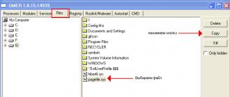
If the disc is unwound, then it is necessary to evaluate it by software. For this it is very convenient to take the program MHDD. You can download it either on the website of the author, or on our website in the "Download" section. This program works from under MS-DOS, therefore it is distributed in the form of a floppy image or ISO image of a CD, from which you can boot. Before using the program it is highly desirable to familiarize yourself with its documentation. To diagnose the hard drive is best connected to the Secondary IDE port or any SATA, depending on the interface of the drive. After downloading the program, select the channel to which the diagnosed drive is connected, and press F2. The program will attempt to read the drive's passport. If the passport of the drive could be counted, and it corresponds to what is indicated on the hard disk label, then the problem is most likely not in the electronics board. An exception to this rule may be the "knocked-out" bits of the interface, which is manifested in the incorrect name of the drive or other "garbage" that appears when reading a passport. For example, the drive is not defined as Toshiba, but as To & hiba.
If everything is correct in the passport, then you can try to scan the disk surface for the presence of bad-blocks on it. This is done using the F4 key.
If there are no bad-blocks on the surface, or there are only a few of them, then the problem is definitely not in the electronics board, and you need to use means of recovering logical problems of the drive, such as R-Studio or Easy Recovery. You can download these programs in the "Download" section of our website.
If the electronics board is damaged (i.e., the drive's passport could not be counted), then its repair or replacement is necessary. This repair is quite complicated and usually comes down to a complete replacement of the board. This question for each disk family is solved in its own way, so we will look at disks by families.
We consider the most common families of drives that are being produced at the moment, or those that have already been taken out of production, but which are the predecessors of current families.
Company stores Seagate.
Seagate drives are divided into two families:
- "Fish-like". (Modeled on Barracuda drives).
- U-series. (Patterned on U-Series Sigates).
For a rough selection of the board on the Seagate “fish-like” series drives, it is necessary to match the version of the Firmware indicated on the label pasted on the HDA. In addition, the amount of cache should not be less than on the original board.
That is, on drives with a cache size of 2 megabytes, you can install boards with a buffer size of 8 megabytes, but not vice versa.
If the rough selection of the board failed, and the drive is still not detected and the BUSU indicator is active in the MHDD program from the top, this means that the board most likely did not fit - the ROM version did not match the overlay version in the drive's service area.
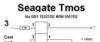
For a "fine" board selection, you need to find out which version of the ROM was in the motherboard. To do this, you need to make a special terminal adapter and connect it to the RS-232 diagnostic interface built into the drive. The adapter adapter is shown in the figure.
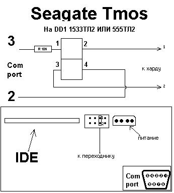
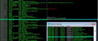
After connecting the drive through the adapter, you must run a terminal program, for example Hyperterminal or Putty at a speed of 9600 bps, and turn on the drive. A drive greeting will appear on the screen, and further diagnostics indicating the reason why the drive is not working. The approximate version of the diagnostics that is displayed on the screen is shown in the figure.
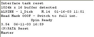
In this case, it is clear that the firmware version is M-14.
If the “native” drive card is damaged so badly that it does not even issue greetings to the terminal, then you need to try to pick up a card with a different ROM version than the one that has already been tried for installation. Different versions of the ROM, with the same version of the Firmware specified on the cover of the HDA, are characteristic of disks, starting with the Barracuda ATA V. In the previous series, for each version of Firmware there was one type of ROM. For models of the Barracuda ATA V family and older ones, this problem can be solved by simply soldering the ROM chip from the “dead” board to the “live” one. For families of drives, starting with Barracuda 7200.7, on some types of boards, a mask ROM is used inside the processor.
With drives Seagate U-series, everything is somewhat simpler. They are similar in this regard to drives Seagate Barracuda ATA 4 and below, i.e. it’s enough for them to choose an electronics board with the same version of Firmaware on the label. In case of a mismatch of the firmware version, you can solder the flash memory chip from one board to another.
Drives Maxtor.
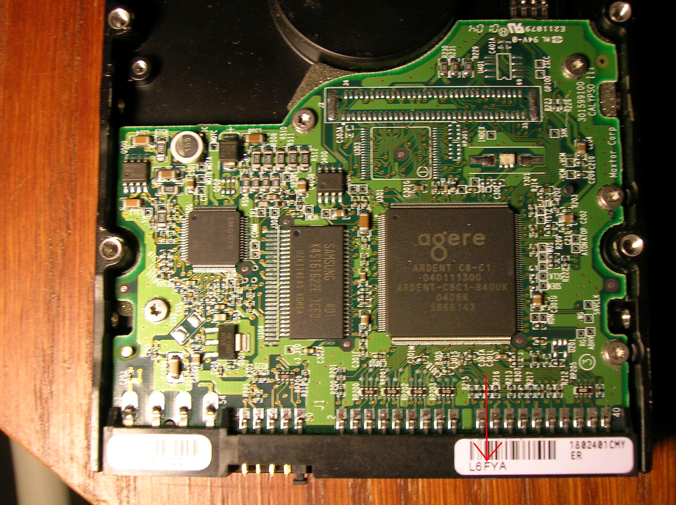
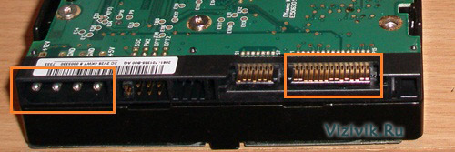
For Maxtor drives, control board malfunctions are quite common. Usually, the driver burns on the board. To replace the board, you must match the labels on the IDE connectors.
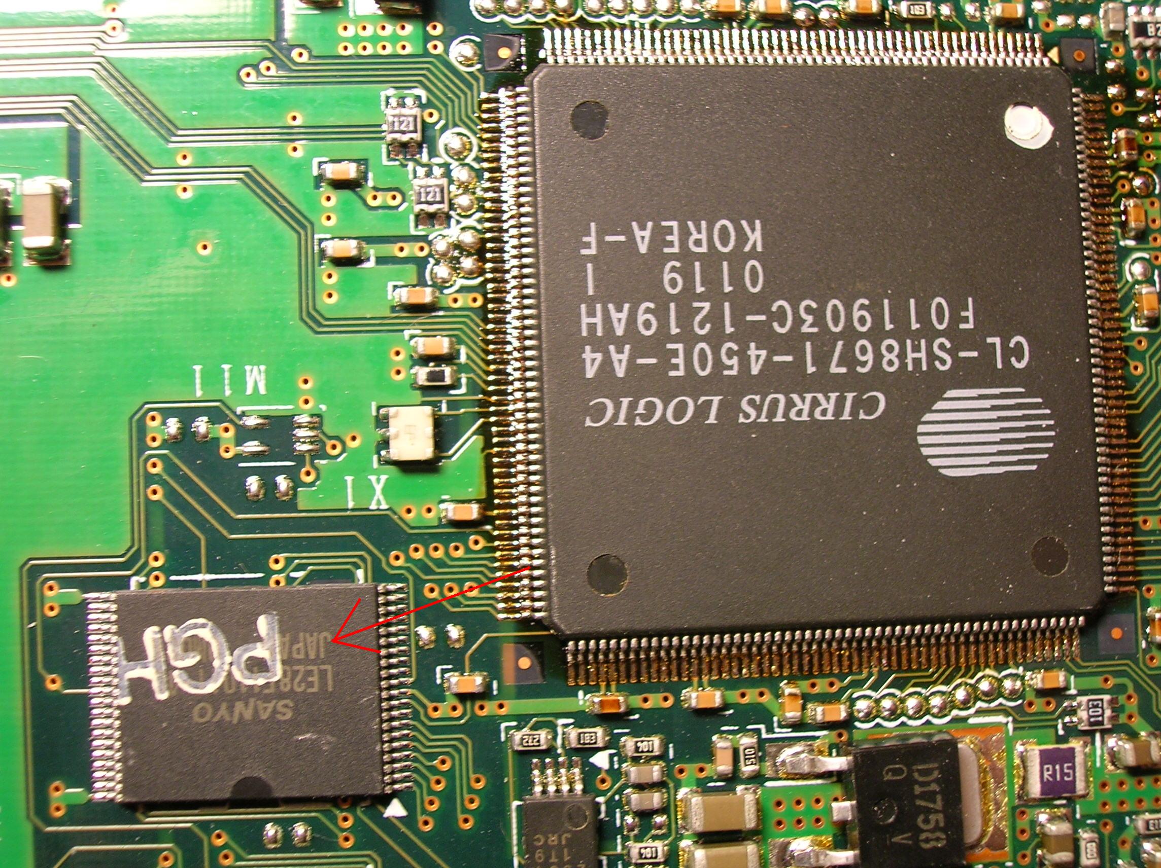
Drives Western digital.
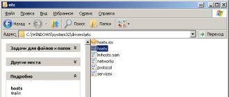
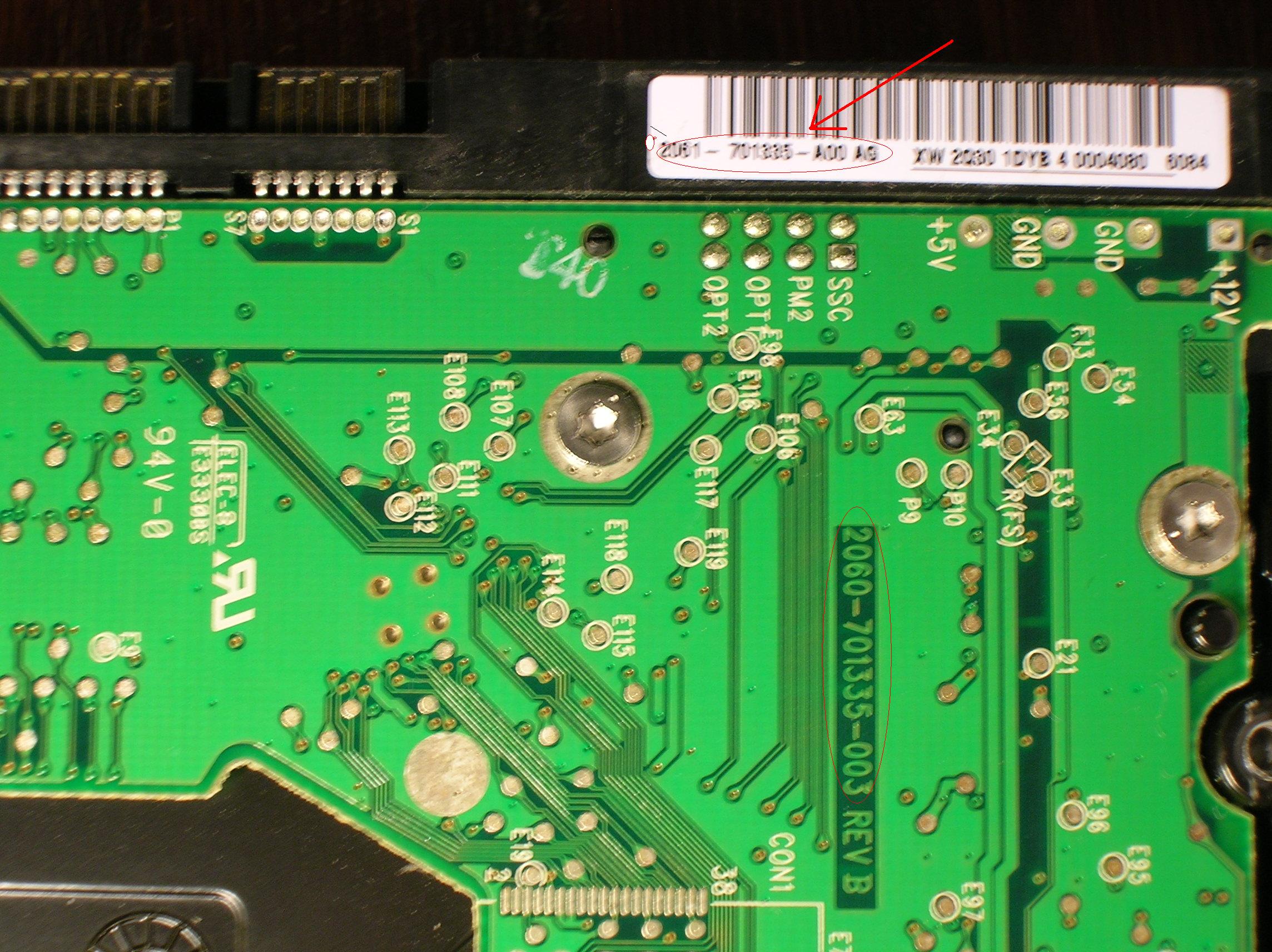
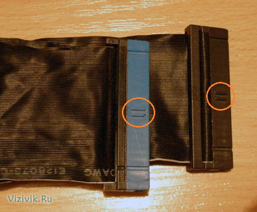
Western digital drives are characterized by a large number of different board versions. To select a suitable board, it is necessary that the boards have identical labels on the IDE connectors. The characters that should match are circled in red. However, besides this, it is necessary to match the ROM version and match the additional parameters in the ROM. Therefore, it is best to also solder the ROM when replacing the board. If you cannot rewrite the ROM, then you should at least use a card from the same disk model. The MDL inscriptions on the cover of the HM unit (see figure) must coincide completely.
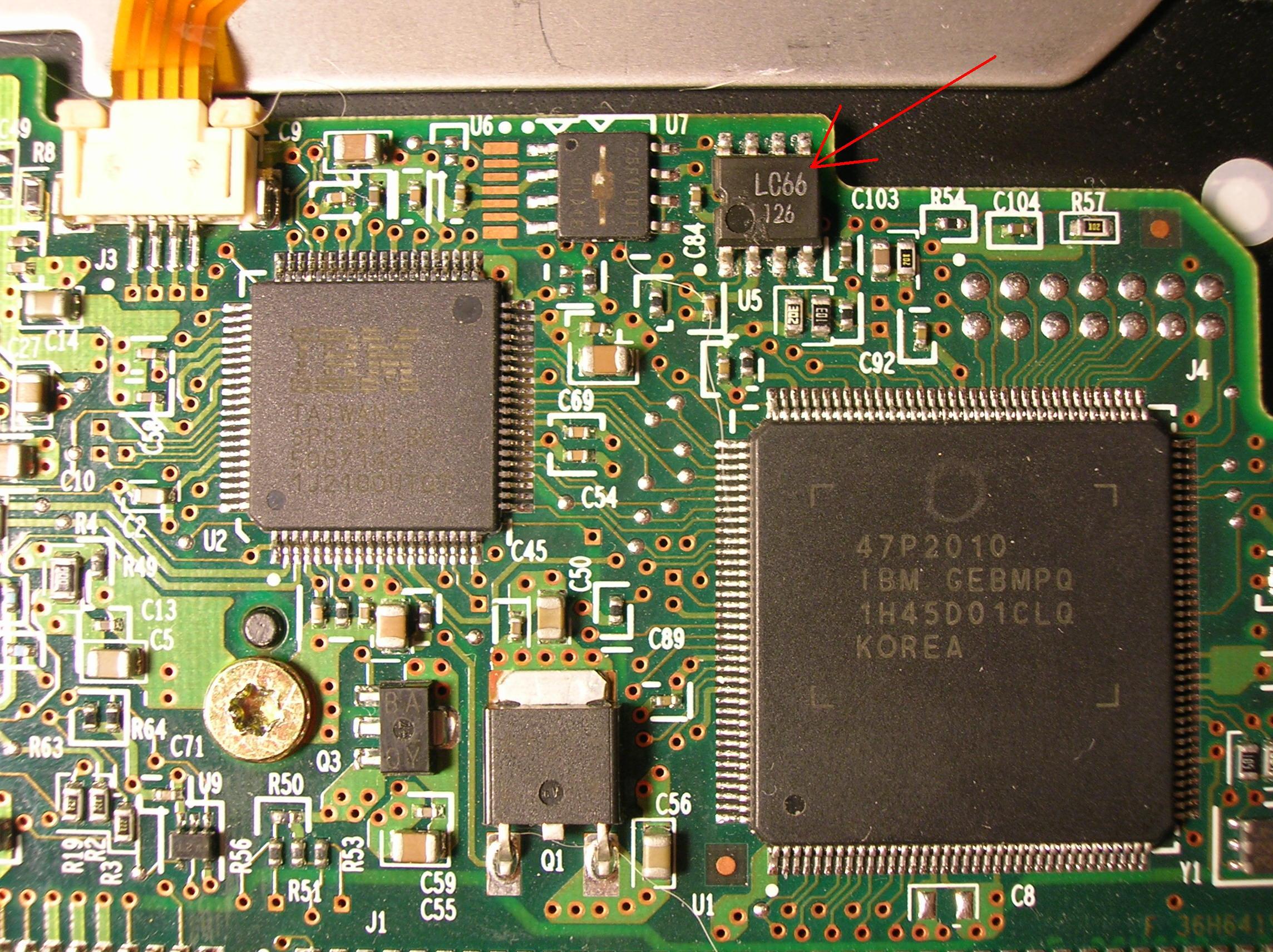
Drives IbmHitachi.
These drives on the board have an NVRAM non-volatile memory chip in which configuration parameters are stored. For relatively old IBM drives, you can simply pick up a board with the same firmware version, but this is quite difficult and usually easier to solder the chip. In some cases, it is desirable to solder also the ROM chip. In the new disks in NVRAM there are also adaptive settings, so the chip will have to be re-soldered anyway. This should be done very carefully, because careless handling can lead to chip damage, and this will greatly complicate or make it completely impossible to recover information from the drive.
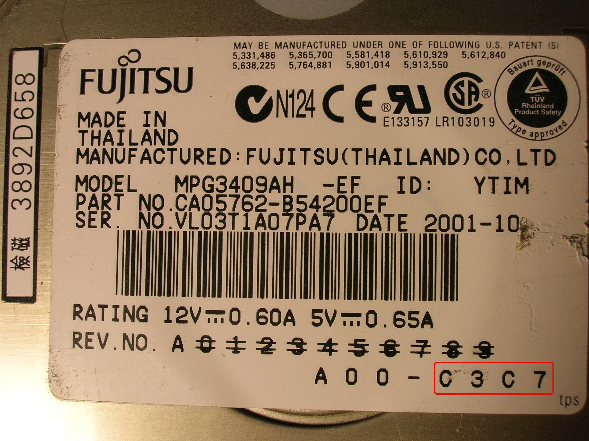
Drives Fujitsu.
These drives have many versions of the ROM. The ROM version is indicated on the cover. In addition to this, some instances of the MPG3XXXAT series of drives have adaptive settings in the ROM. In addition, ROM is a map of heads, which sometimes also matters. Therefore, it is better to re-read the ROM.
Of course, in this article it is impossible to highlight all the subtleties of repairing drives, and besides, in addition to knowledge, you also need to have some experience and skills to handle these "devices".
Therefore, if after reading the article and taking the measures described in it, your disk has not earned, then perhaps you should not continue to torment it and finally break it, but it makes sense to turn to experts?
Golovnyak Sergey.
Leading Specialist
Sergol group
If there are problems with the power supply of the computer, due to power surges, the hard disk controller suffers in addition to the motherboard.
The controller may burn due to improper connection of the power connector (polarity reversal). When disconnecting or connecting the hard disk "hot", i.e. while the computer is running.
The computer does not turn on with the hard drive connected.
If the computer does not turn on with the hard drive, and after shutting it down normally starts, then the problem is with this hard drive. This is usually associated with electrical breakdown of the hard disk. Often, due to a voltage surge, breakdown of the HDD controller elements occurs and a short circuit (short circuit) may occur. When you try to turn on the computer with a hard disk having a short circuit, the protection of the power supply is activated and the computer immediately turns off.
Hard disk recovery begins with the diagnosis and repair of the HDD controller. After the controller is restored, the hard drive is fully diagnosed for correct operation of the hard disk drive's magnetic head unit, determining the read and write speed of the drive.
During electrical breakdown, various options for damage to the controller and the hard disk itself are possible:
1. Burnout HDD controller only.
In this case, repairing the hard disk is limited only by restoring the functionality of its controller (replacing burnt items), or replacing it with a flashing ROM to work correctly with this hard disk. In this case, after repairing the controller or replacing it, the hard disk will work normally.

2. Damage to the hard disk controller and partial loss of performance of the magnetic heads unit.
The hard drive after repairing the controller may be determined by the operating system, but not working normally. For example, it stops working in UDMA mode. In this case, HDD repair may not be possible. Data recovery (if necessary) is carried out by selecting a reading mode for successfully reading the information.
3. Damage to the hard disk controller and failure of the hdd head switch.
 This is the most "sad" option. In this case, HDD repair is completely impossible. The switch chip is located inside the containment on the block of magnetic heads. It performs switching (switching) of data streams during reading and writing by a hard disk to a specific magnetic head. Data recovery from the hard disk is possible only by replacing the HDD magnetic head unit or soldering the switch to the head unit and then selecting the hard disk read mode.
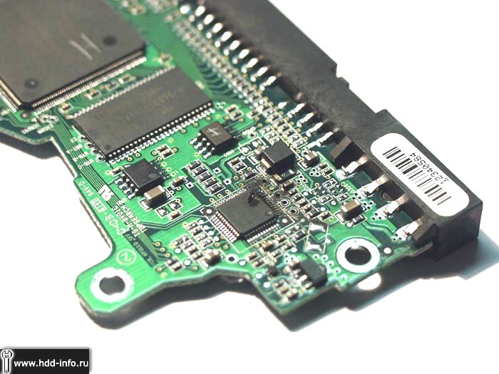
If the tracks on the HDD controller are burned out - this is a bad sign. This suggests that there was an impact by large currents. Accordingly, the elements between which the tracks burned down also suffered. In the figure, burnt tracks connect the hard disk drive spindle motor chip with elements of its strapping. In 99% of cases, this microcircuit also burned out.
 The photo shows a burnt-down spindle motor chip on a Seagate hard disk controller.
If the hard disk controller is electrically damaged, the elements that are directly near the hard disk power connector should fail first. The photo shows the hard disk controller after prolonged exposure to increased voltage. It can be shown that the controller "burned to the ground". And it burned down in the place where the connector is located connecting the controller and the hard disk area of the hard disk.
In this article we will consider the installation of hard disk drives. In particular, consider their configuration and physical installation.
In order to install a hard disk into your computer, you need to do the following:
- configure the drive;
- configure the controller or interface device;
- install the drive in the computer case;
- configure the system as a whole for disk recognition;
- perform logical partitioning of the disk;
- perform high-level formatting of partitions or volumes.
Before proceeding with the installation of a hard disk, it is advisable to familiarize yourself with the documentation for this drive, controller or main adapter, system BIOS and some other computer devices. But, as a rule, this will give nothing to a simple user, so the documentation can be put aside. In modern computer systems, it is optional.
If, after all, you decide to familiarize yourself with the documentation, the collecting company will provide you only limited information about this device. As a rule, complete documentation should be searched and downloaded from the device manufacturer’s website. The same applies to other devices on most systems that are on the market today.
Hard drive configuration
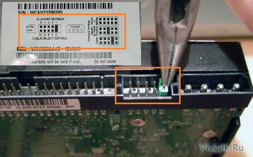
Before you proceed to the installation of a hard disk, it must be configured. IDE drives most often require a master-slave switch, or you can also use the Cable Select option and an 80-core cable.
You do not need to install these jumpers to configure Serial ATA hard drives. There are cases that nevertheless drives have such jumpers installed directly at the factory.
SATA hard drives connect to the SATA controller using a cable to form a point-to-point connection.
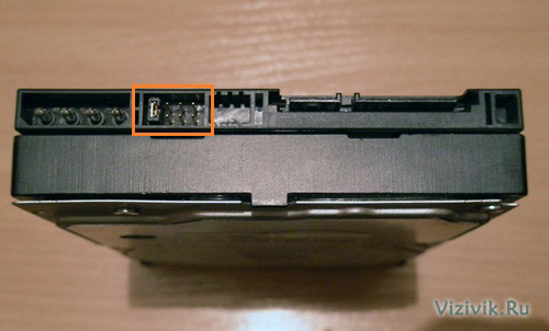
Unlike hard drives based on the parallel ATA interface (outdated), SATA drives do not have any master or slave devices. The picture shows that some SATA drives have jumpers to allow compatibility. In modern hard drives with a data transfer rate of 300/150 Mbit / s to switch to a slower mode, which is necessary for the correct operation of the old controllers, you need to rearrange the jumper. For reasons of compatibility with drivers and other software, most controllers can operate in a “compatibility mode”, in which the master-slave configuration is emulated, but this mode is not physically implemented.
Hard disk controller configuration
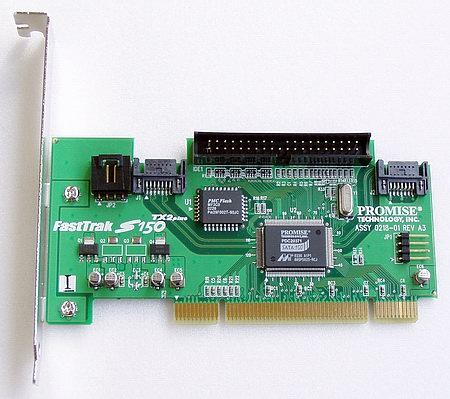
The hard disk controller in older models is installed in the slot of the motherboard. All recently developed IDE and SATA drives have an integrated controller on the motherboard. Almost always, the ATA device controller is integrated into the motherboard and configured using the BIOS setup utility. In this case, a separate controller does not exist. Some systems, in addition to an integrated controller, may have a controller on an expansion card. This situation can occur when the integrated controller does not support faster data exchange modes (300 Mbit / s for SATA and 133 Mbit / s for PATA) typical of new hard drives.
In such cases, you do not need to resort to installing the controller in the motherboard, it is better to upgrade the motherboard itself, so you will get additional functionality and spend a little more.
There are also such cases when adding a controller card makes sense, for example, a new SATA disk is “suspended” on an old motherboard that does not have this controller.
Controllers on expansion cards require a certain combination of the following system resources:
- boot ROM address (optional);
- interrupt (IRQ);
- direct memory access (DMA) channel;
- i / O port address
Not all controllers use each of these resources, but there are some. In most cases, modern controllers and systems that support Plug and Play technology are automatically configured by the basic computer I / O system and operating system. The system allocates such resources that do not lead to conflicts with other devices of the computer.
If the operating system or hardware does not support Plug and Play, then the adapter must be manually configured. Some controller cards come with utilities that allow you to program this configuration, while other controllers have a number of switches or jumpers.
The ATA interface driver is part of the computer’s standard BIOS and allows booting from PATA and SATA devices. In such systems, containing the SATA interface on the motherboard, the driver of this interface is also built into the BIOS. The BIOS provides the device functionality that the system needs to access the disk before it can download any file from it.
Notice!
Although the Windows operating system (OS) supports standard IDE / ATA drivers, this type of interface usually integrates into the components of the south bridge or the I / O controller chipset of the motherboard and requires the download of special drivers. When using a motherboard that is newer than your OS version (for example, a new motherboard purchased in 2010 that runs on Windows XP), make sure that the chipset drivers are installed immediately after installing Windows shipped with motherboard. If the controller supports SATA in the Advanced Host Controller Interface (ACHI) mode or a SATA RAID array (Redundant Array of Independent Disks is a redundant array of independent disks), and the computer is running Windows XP or an earlier version, as a rule, installation is required driver that is on a diskette or pre-recorded on the Windows installation disc.
Keep in mind that all of these drivers are included in the Windows Vista and 7 installation. If the controller is older than the operating system you are installing, the necessary drivers will most likely be included in the installation CD. At the same time, it is always recommended to search the Internet for the latest version of the controller driver and install it immediately after the operating system.
There are SATA controllers that have their own BIOS that supports ACHI, RAID, large disks, or other functions. If you are not going to use these functions or the motherboard BIOS itself has this support, then it is not necessary to use the controller BIOS. Many controllers on expansion cards have switches, jumpers, or support programs that allow you to enable or disable BIOS support.
In addition to the BIOS boot functions, the controller provides other functions, such as:
- configuring a RAID array;
- controller configuration;
- diagnostics.
If the controller's BIOS is enabled, to place it, you need an address space in the high memory area (UMA), which occupies the last 384 KB within the first megabyte of system memory. The upper memory is divided into three sections with two segments each 64 KB in size, with the first section being allotted for the video adapter memory and the last one for the system BIOS. The C000h and D000h segments are reserved for BIOS adapters, in particular for hard disk controllers and graphics controllers.
Notice!
The memory areas occupied by the BIOS of various adapters should not overlap. On most boards, there are switches and jumpers with which you can change the BIOS addresses, sometimes it can be done programmatically, thereby preventing a possible conflict.
Mounting hard drives
Hard drives are mounted in the computer case. To do this, you need the appropriate screws, brackets, front panel, etc.
For the installation of some drives will require plastic guides that are attached to the device on both sides and allow you to install it in the appropriate place in the case.
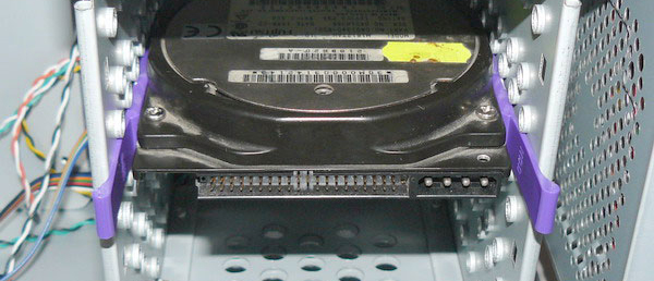
These guides should be attached to the computer case or to the hard disk when purchased.
Since PATA and SATA devices use different types of cables, check to see if the cable matches the controller and drive. To use PATA mode with a speed of 66 Mbps and faster (up to 133 Mbps), you will need an 80-core cable. It is also recommended to use it at lower data rates, such as 33 Mbps or less. To determine what kind of cable you have (40- or 80-wire), count the hillocks on the cable - each hillock corresponds to one core. One of the characteristic features of an 80-core cable is the color of its plugs: inserted into the motherboard is colored blue, and inserted into the master and slave devices is black and gray, respectively.

If you plan to install a 3.5-inch hard drive in a 5.25-inch frame, you will need a different type of mounting pad. Most 3.5-inch disks have such overlays in the kit.
They can also be included in the package.

Notice!
It is necessary to choose the length of the connecting cable (loop). In some cases, the cable does not reach the new hard drive. Try to move it to the nearest compartment, or use a longer cable. The length of the IDE drive cable is limited to 45 cm, the shorter the better. However, in the set of some cases you can find longer cables, up to 67 cm, besides having 80 wires. Long cables, especially those with non-standard, нест ‘rounded’ ’length, are not recommended, especially for disks with a data transfer rate of 133 Mbps. Using too long cables causes transmission time errors and signal weakening; data may also be corrupted on disk. If you use a cable longer than 45 cm, then, as they say, you create problems for yourself.
After unpacking a new hard disk, you should have the following:
- the device itself;
- software (optional);
- mounting plates and screws.
Devices supplied as OEMs, i.e. in packages, except themselves may not have anything in the kit. In this case, you yourself will have to take care of the cables, screws and other accessories.
Mounting an ATA (PATA) hard drive
To mount an ATA hard drive, follow these steps:
1. See if there is an unused 40-core IDE connector in the computer. With a Pentium processor, four IDE devices can be installed on a computer (two for each channel).
Tip!
To improve the performance of simultaneously used devices, such as drives and hard drives on optical disks, they are connected to different cables. Hard disk and drive is not recommended to "hang" on one cable.
2. Notice how the cable is connected to the drive. The red wire of the power cable is connected to the first pin of the drive connector. Despite the fact that the plug has a special key from incorrect connection to the hard disk, it can easily be connected incorrectly, which will lead to failure of the device.

The first contact of the cable is most often oriented closer to the power connector of the device. On the cable there is a special key to properly connect to the device.
Tip!
Remember that modern ATA hard drives require an 80-wire cable for Ultra-DMA (66-133 Mbps) high-speed operation, and you can use it to connect older devices. A 40-wire cable can be used to connect devices with a speed of 33 Mbps or less. The advantage of the 80-pin cable is that the devices will have to install only the CS (Cable Select) jumper, and you do not need to choose which device will be the master and which the slave. Today, ATA-connection is already quite rare, all modern hard drives are connected via SATA interface.
3. Set the Master / Slave / Cable Select switches on the back of the hard drive. When using an 80-pin cable, it is enough to install the Cable Select jumper on all devices. Otherwise, one of the devices connected to the loop must be master (master) and the other slave (slave). Please note that some outdated devices, when used as a leader in a pair with another slave, require simultaneous installation of Master and Slave jumpers. But today, it is unlikely you will come across such hard drives in your hands.
4. Place the drive in the 3.5-inch chassis compartment and fasten it with screws. When performing this operation, it is impossible to exert considerable mechanical effort - the drive must be free to take its place in the case.
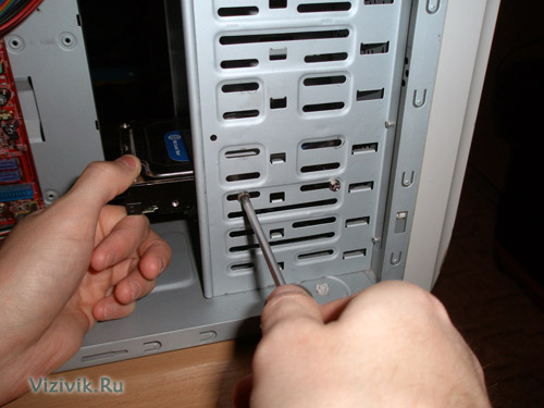
Make sure the screws are not too long. If the screw is longer than the depth of the hole into which it will be screwed, you can damage the device and disrupt the thread.
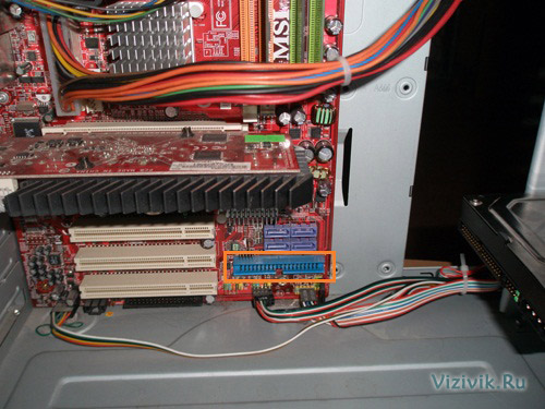
5. Attach the interface cable to the back of the drive. If an 80-pin cable is used, the blue plug must be plugged into the motherboard slot, the black plug into the master device slot, and the gray plug (usually the middle one) into the slot of the slave.
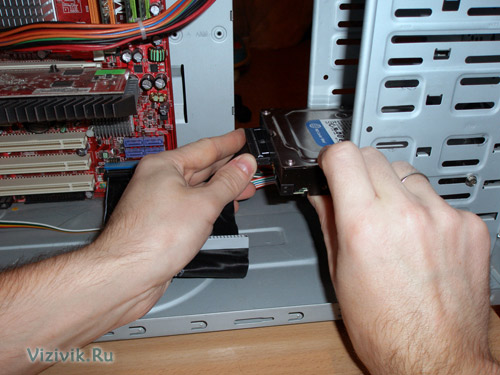
6. Connect the power cable to the hard drive, most often it is four-core with a standard connector.
This completes the installation of the ATA hard drive.
Consider connecting SATA hard drives.
Mounting SATA Hard Drives
The step-by-step procedure for installing a SATA hard drive is somewhat different from installing an ATA drive.
1. Check if there are unused SATA connectors in the system.

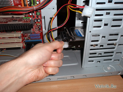
2. Gently insert the hard drive into the compartment of the appropriate size, using pads if necessary, and tighten the fastening screws.
3. Connect the SATA data cable to the SATA controller. Data cables can be combined in a single sheath with a SATA power cable. When using a separate data cable, one connector is connected to the drive and the other to the SATA controller.
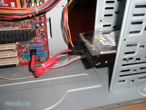
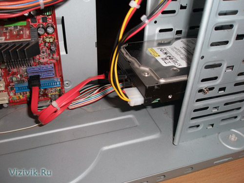
4. Connect the appropriate power cable to the drive. Some SATA devices have two power connectors: standard 4-pin and special 15-pin - in this case, apply power to any of them (but not two at the same time). If the device has only a 15-pin power connection, and the power supply does not offer such a plug, you will have to additionally purchase a special adapter “4 to 15” (if it is not included in the device kit).
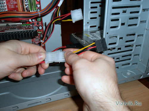
Power connection through a special adapter "4 to 15"
Attention!If the device has 2 power sockets at the same time (standard, 4-pin, and SATA-type, 15-pin), in no case do not apply power to both connectors at the same time, otherwise you may damage the device.
system configuration
After the hard disk is mounted in the computer case, you can begin to configure the system. The computer needs to provide information about the drive so that it can be loaded at power on.
On Windows 2000, XP, Vista and 7, the command is used. They can be found on the boot CD of the operating system. If the operating system is installed on a new disk, its division and formatting will be performed as part of the overall OS installation process.
If you want, you can create partitions and perform formatting manually before installing the operating system, but this will have to use special programs. It is easier to do this during the installation of the system and its means.
Automatically detect the type of hard disk
Virtually all PATA and SATA drives in modern BIOS provide automatic type detection, i.e. from the drive on request, the system reads its characteristics and the necessary parameters. With this approach, errors are practically excluded, which can be made when entering parameters manually.
And so, let's get started.
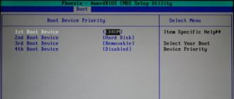
1. Turn on the computer and press the key required to enter the BIOS settings, usually Delete or F1. If the BIOS provides for automatic detection of devices, it is recommended to set this mode, since the optimal parameters of the device will be determined. SATA devices can also support ACHI mode and group multiple devices into a RAID array. Set the ACHI option for SATA drives, if supported, and exit the BIOS setup program.
2. Reboot the system. If the installed device is not bootable, and you are running Windows XP or a later version of this OS, the new drive will be automatically detected during the boot process and the necessary drivers will be installed for it. It should be noted that the system will not see the new device as a volume (that is, it will not be assigned a letter) until the disk partitions are created and their formatting is performed.
If the new device is bootable, you will have to boot from the CD again to create partitions on the new disk, perform formatting, and install an operating system on it. If the motherboard supports SATA in ACHI mode or SATA RAID arrays and you are running Windows XP or an earlier version of this OS, you will need to use a controller driver diskette or rewrite these drivers on the Windows installation disk or use a floppy disk drive to install the device. Otherwise, the system does not recognize the hard disk and the installation process will not be possible.
I note that all the necessary drivers are already integrated into the new Windows Vista and 7 operating systems, and during their installation, there are no problems with the definition of the hard disk controller.
Manually determine the type of drive
If your computer has a motherboard that does not support automatic detection, you will have to enter the appropriate information in the BIOS manually. Several standard combinations are available in the BIOS, however, they are most likely outdated, as they provide support for drives of only a few hundred megabytes, or even less. Most often you will have to select a custom hard disk type, and then specify the values of the following parameters:
- number of cylinders;
- number of heads;
- number of sectors per track.
The required parameter values can be found in the documentation that came with the hard disk, but they can be printed on a sticker on the hard disk case. Be sure to remember or write them down.
The latter option is preferable, since you will need the parameter values if the system BIOS suddenly “forgets” them due to a dead battery on the motherboard. Recorded information is best stored directly inside the system unit, for example, they can be glued to the body with adhesive tape. Sometimes it saves a lot of time.
In the event that you are unable to determine the correct values of the parameters of your hard disk, refer to the website of the manufacturer. You can also use one of the diagnostic tools available for download via the Internet.
Depending on the BIOS manufacturer and its version, you are given the opportunity to configure other parameters of the hard disk, in particular, the data transfer mode and logical unit addressing.
Still, if the BIOS of your motherboard does not support the automatic detection function, then you need to think about upgrading your computer and replacing the outdated motherboard with a more modern one, which includes many different functions, including support for modern hard drives.
The hard disk consists of two main parts: the HDA and the controller.
Figure 1 - block - hard disk layout

Figure 2 - The main elements of the hard disk design
1.2. Hard drive device
The entire hard drive, as a device, is divided, as we have noted, into two major components: an electronics board and a pressure zone or “jar”, inside which there are magnetic disks, a block of magnetic heads, and a spindle engine.

 Figure 3- The appearance of the hard drive company MAXTOR
1.3. Electronics board (controller)
An electronics board or controller on a hard disk is essentially a small computer.
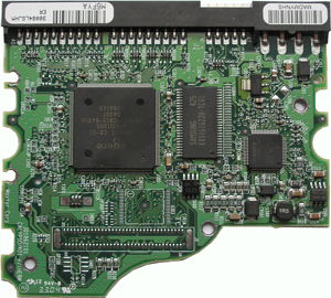 Figure 4 - External view of the MAXTOR hard drive electronics (controller) card
On the board in modern hard drives you can find a processor, memory (RAM), ROM. The processor processes the data received from the heads and converts them into a computer-readable “language” —ATA standard. He does it, like a computer in RAM. ROM is needed to start, as BIOS on the motherboard. What the engine control chip does is clear from its name. When enabled, the controller board reads service information and if it is correct, the hard disk starts. But what to do if the electronics board fails and, as a result, there is no access to documents, photos, etc., because the hard drive has broken?
Of course, there is a desire to change this ill-fated payment for a similar one from the hard drive of the “donor”, because they are so similar, and consider their information. But not everything is as simple as it seems at first glance. As you know, progress does not stand still, and hard drive manufacturers are constantly improving their products, making changes in the technology of hard drives and, as a result, new lines of models of hard drives appear that are notable for recording density, firmware, design of individual nodes, electronics circuitry. It is for this reason that most controllers have fine tuning parameters and are not interchangeable.
Therefore, the conclusion: not having complete information about the interchangeability of controllers on hard drives, unqualified independent data recovery attempts in case of replacing the electronics board can not only aggravate the cause of the breakdown, but also significantly reduce the chances of successful recovery of information from the HDD.
Footnote:
Hard drive controllers
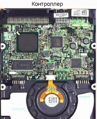
Risunk 5 - Controller
The drive controller itself is physically located on the electronics board and is designed to provide conversion operations and transfer information from the read / write heads to the drive interface. Often, a controller is called a drive interface or a PC interface with a drive, which, in general, is not true.
The hard disk controller is a complex device - a microcomputer, with its own processor, RAM and ROM, circuits and input / output system, etc. However, in most cases, manufacturers place them in one or two microchips.
The controller is involved in a variety of data stream conversion operations. Since the length of the tracks is uneven, the data on different tracks must be recorded unevenly. This becomes a problem, compared with floppy disks, for high-density media (the number of tracks is more than 1000). Simple controllers usually record the same amount of information on each track, regardless of its length. To do this, the controller packs the data more closely, starting with the track defined by the account. A cylinder (in the case of more than one disk, all tracks one under the other are called a cylinder) from which the more dense data packing starts is called a Starting Cylinder for Precompensation (SCP). To compensate for the distortion of information when reading, data is recorded with a preliminary offset of bits, which takes into account the distortions.
Our clients often ask us about how we recover their disks. In this article I will try to tell about these processes in more detail, but at the same time, without disclosing professional secrets. Once again I want to warn all users against independent attempts at self-treatment, HDD is a technically complex device with precision mechanics, which can be restored only in special laboratories.
In this photo you can see the typical design of the hard drive.
Bad blocks -the most common problem in modern drives. It appears as a strong slowdown while the operating system is running, messages appear about the inability to write or read files, loss of logical drives (if there are several), or in severe cases, after detecting the disk in the BIOS, the computer does not start the operating system or the computer reboots cyclically .
The consequences of this type of malfunction usually manifest themselves in the form of file system corruption. Serious consequences for information is usually not. We do not use DataExtractor when copying and restoring data. Our modern developments allow us to remove information from a hard drive that has up to several million bad-blocks with virtually no damage.
The technology of data recovery in such cases is to use special software tools, with the help of which a full sector-by-sector copy is made to another working disk (cloning). With this copying, special algorithms are used when the hard disk does not “slow down” on the bad blocks, and when determining the damaged sector it instantly skips it and proceeds to the next one, preventing the loss of readiness (hang) of the disk. Sometimes the cause of badly readable sectors is a damaged head, in this case it is necessary to replace the entire BMG.
With this fault, the repair of the disk itself is impossible or impractical due to the large time spent on this process.
Failure of the magnetic heads unit - The second by the number of breakdowns in modern HDD. It appears in the form of extraneous sounds such as clicks, and the disc is not detected in the BIOS, since cannot read service information from pancakes. Also, with this fault, there are cases when one head fails and on the surface on which it reads no service information is recorded, in this case the disk will be detected in the BIOS, but will not be read by periodic zones on the surface, i.e. will not read only on this faulty head.
The method of data recovery is as follows: you need to find a working disk of a similar model, and rearrange from it a good block of heads on the hard drive, from which you need to remove data. Further, as in the previous case, sector-by-sector copying (cloning) of information to another working hard drive is performed. Connect the restored hard drive to Windows and rewrite the information on the files through the explorer is fraught, because most likely he will again fail. After the completion of the work, neither the source disk nor the donor disk can be used further and it will not be possible to assemble one of the two workers (as many clients ask for) out of two, because the opened HDD will no longer work fully. at the factory, during the manufacturing process, the hard drives are calibrated (tuned) after the assembly of the HDA and any intervention in mechanical components leads to an inevitable drop in performance (speed and reliability).
The reasons for the failure of the BMG can be: technological defects, external mechanical effects on the hard drive (impact, fall), damage to the magnetic layer of the disk (Bad blocks, blow heads on the disk surface).
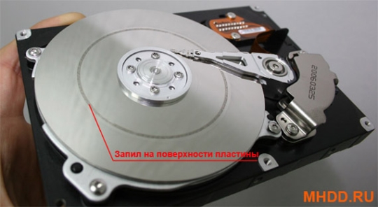
The photo shows a cylindrical gash from the heads on the surface of the Samsung disk, the removal of data in such cases is impossible.
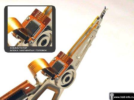
Failure of the BMG switch- this fault can be divided, as it were, into two cases: the first case is when the switch chip itself goes out of order, it often happens on HDDs of Quantum AS, Maxtor D540 and Maxtor D740 models; and the second case, when the switch fails as a result of electrical breakdown, this is accompanied with burnout of the external electronics board. More precisely, first the external HDD controller burns out, and only then the switch inside the HDA as though pierces through. In the first case, the hard drive will knock, in the second case, respectively, will not spin, and if you replace the burnt electronics, it will also start knocking. There are two ways of data recovery: the first is to solder the switch chip by taking it from a similar HDD; and the second way is to replace the entire block of magnetic heads with the switch. It is easier, of course, to replace the entire BMG, but unfortunately this is not always useful, on some hard drives, for example: Western Digital, Quantum AS and Maxtor D540 are very poor interchangeability of mechanics and it often happens that it is not possible to find a suitable BMG from a similar donor.

In the photo you can see the Magnetic Heads Unit (BMG) from the Maxtor DiamomdMax Plus 9 80Gb HDD. In the center of the BMG on a flexible cable going to the external HDD electronics board there is a switch chip, in the left part of the photo there are two magnetic heads that are mounted on metal plates with a wide range of elastic deformation.
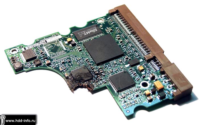
Hard Drive Electronics Failure -the most common cause is electrical breakdown. A disk with such a malfunction does not spin, and burned-out items can often be seen on the controller board. The reason for this may be a bad power supply or incorrect connection of the power connector to the HDD. To restore the hard drive and remove the data, it is necessary to replace the electronics from the same HDD, previously overwriting the unique service firmware from the old controller with the new controller. The times when the boards for disks of the same model were interchangeable have already passed. Self-replacement of electronics can be fraught with the final HDD failure. This fault is often accompanied by the burnout of the switch, in this case, with a simple replacement of the electronics board, its repeated failure is possible. If the switch also burned out the disk, then it is necessary to replace the entire block of heads from the same HDD.

The photo shows the electronics board from Western Digital HDD with a burnt-out control chip for the magnetic head unit, the damage is indicated by arrows.
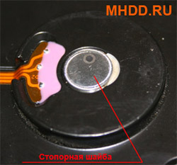
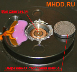
Wedge Engine Bearing - this fault often occurs as a result of physical impact on the disk, for example, the fall of the HDD. At the same time, the disk does not rotate, but makes quiet, buzzing sounds — these are engine attempts to spin the shaft. The fault is divided into two cases: the first is when the axis of the motor shaft is wedged with an end on the bearing lock washer, in this case we remove the lock washer with the help of special equipment, freeing the motor axis; in the second case, the shaft axis is wedged over the surface of the bearing sleeve, and in this case it is necessary to rearrange the magnetic plates to another HDA with a working bearing while preserving the interdisk phase (pancake offset angle relative to each other).
It should be noted that the second case refers to the extremely complex and very expensive. In the overwhelming majority of firms, the plates of the disk are rearranged one by one, which does not allow to precisely preserve the original position of the plates relative to each other. We, however, have plate swapping technology in a “batch method”, i.e. The disks are rigidly fixed relative to each other by a special device and are rearranged at once in a single package without offset, which allows you to recover information in the event of a given fault in 100% of cases.
Damaged firmware - this fault has manifested itself widely on such disks as Fujitsu MPG and thin Maxtor models. On modern hard drives, problems with the service microcode are extremely rare. When such a malfunction drives usually cease to be determined in the BIOS, or they are defined there incorrectly. The principle of the HDD is such that at first the disk loads the service firmware, and only then gives access to the user data area. Recovery of the disk in such cases is performed using special software and hardware systems (such as PC3000), which at the level of technical teams can work with the firmware of the hard drive.
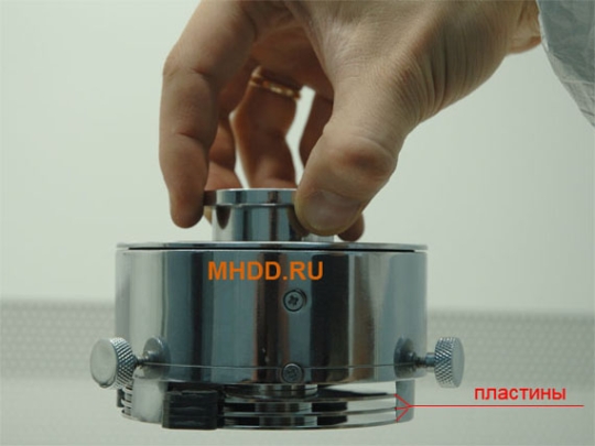
Sticking BMG on the surface of the plates - by symptoms, this fault is identical to the case with a wedge of the engine bearing, i.e. the disk does not rotate, but makes quiet, buzzing sounds. But this problem occurs mainly on notebook disks and rarely on 3.5 ”IBM or Hitachi only on those hard drives where the heads park outside the pancakes on a special external stand (ramp). Quite often, after sticking, the heads fail, and to produce them you need to replace them, moving them from a similar HDD. The figure shows an example of a hard drive with stuck heads. To solve this problem with the help of special tools, the heads are brought back to the parking attendant and after that they are replaced. Inexperienced users who independently uncover the HDD HDD often try to remove the heads themselves, but due to the lack of the necessary knowledge, tools and technologies, they simply bend the magnetic heads (as they strongly stick to the magnetic plates) and they also scratch the surface of the HDD, which subsequently makes it impossible to remove data even for professionals.

In the last figure, you can see the Toshiba MK4026GAX HDD with heads stuck on the magnetic plate, for some reason they could not park on the ramp and fell on the surface of the disk.