Wireless Internet - this is one of those things without which it is already impossible to imagine life. Now you can use gadgets from anywhere in your home and office, game consoles, internet home appliances. But it takes good potential to run all of these things at the same time.
Most the simplest way enhance wireless signal - this is the use of an external amplifier for a router, which you can buy, or make an antenna yourself. As you gain experience and learn the basics, you better understand how to make the right choice.
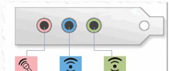
Antenna polarization
Wi-Fi communication relies on radio frequency energy that is transmitted and received over antennas.
Receiving and transmitting antennas are devices that emit radio waves when electrical energy is supplied. Radio waves, like all waves in the electromagnetic spectrum, are measured in units of frequency Hertz. When referring to radio waves, the term "wavelength" is often used. Wavelength (meters) \u003d 300 / frequency (MHz). This relationship between frequency and wavelength is especially important for design and antenna design.
The orientation of the antenna relative to the earth's surface is called its "polarization". Structures that are designed for radio waves oriented generally parallel to the earth's surface are called "horizontal". If the impact is directed at right angles to the earth's surface, then we are talking about "vertical" structures.
Some antennas can be used in any polarization by simply changing the position. Factors associated with choosing one polarization over another include operating frequency, desired coverage, mechanical constraints, and common practice.

It is very important to consider that all antennas in a communication system must use the same polarization. Circular or elliptical polarization is sometimes used to maximize compatibility.
Strengthening the receiving power and signal of the router
An antenna transmits (and receives) radio waves better in certain directions, thereby increasing the effective radiated power.
Note! The total radiated power does not increase, but simply becomes stronger in one or more directions and weaker in other directions.
This "boost" is applied to both the transmitted and received signal. The unit for quantitative gain is the decibel or dB, which was named after Alexander Graham Bell.
Important! Higher dB values \u200b\u200bindicate higher gain.
The main types of antennas
What to consider when designing an antenna? To work on signal amplification, it is always important to remember some of the features of signal transmission over distances. The choice of the type of antenna device can significantly affect the range and stability of communication.
All Wi Fi antennas are divided into two types:
- directed,
- omnidirectional.
Which, in turn, are:
- internal,
- outdoor.
In addition, when installing the device, you need to take into account the following: a mismatch in the polarization of the access points will lead to the fact that in one of the positions the quality level will increase, and in the other it will disappear altogether.
Omnidirectional
The best option is to expand the range home internet system is installation external antenna with good gain and omnidirectionality. An omnidirectional antenna is usually a vertically polarized antenna. In a remote area, where cellular communication is weak, it makes no sense to install such a device. The option is more applicable in urban environments.
Remember! Omnidirectional antenna models naturally interfere with each other if not placed correctly in the immediate vicinity of a conventional router.

One type of high gain omnidirectional antenna is a vertical collinear wi fi antenna with one feed point and element phasing.
Directional
An antenna is a passive device that does not add power to the signal. However, there are methods to increase the proportion of energy transferred in a certain direction by reducing the proportion of energy transferred in other directions.
If you use directional antenna amplifiers, you can significantly improve the coverage area of \u200b\u200bWi-Fi.

One of the least common (due to its high cost) types of antennas in cellular communication are sectoral antennas. The devices allow you to provide high level Internet connections if using multi-panel installation schemes. Vertical and horizontal focusing of the beams (90, 120 degrees) prevents interference from other antennas.
How to connect free internet wi-fi
There are several ways to amplify the signal so that you can connect to accessible points or to a neighbor's router who shares his Wi-Fi password.
Do-it-yourself powerful antenna
You can make a wifi antenna amplifier for directional action yourself, since there are many similar schemes on today's Internet. For example, a double biquad antenna with a gain of 12 dB. For assembly, you need copper wire with a diameter of 2 to 3 mm and a length of 300 mm.
A plate made of foil-clad getinax can be used as a reflector. Foil-clad getinax is a pressed paper impregnated with an adhesive and covered with copper foil. If this is not the case, then you can use any metal, for example, the lid of an old system unit or an ordinary beer can.
The first thing to start with is to bend a double figure eight from a wire with sides of squares 30 mm. To do this, the wire must be marked into 8 equal parts, bend it in the marked places at an angle of 90 degrees using pliers. The result should be a figure-eight antenna.
Next, you need to cut out the reflector from the getinax plate. Mark the center on the plate and drill two holes on it: for the antenna and the wire exit. The distance between the wire and the plate must be at least 15 mm.
Next, you need a wi fi adapter, or rather its small antenna. After drilling a hole in the adapter body, the wire is displayed. The center wire is soldered to the figure eight, and the winding to the leg. This is how the wifi antenna double biquadrat works. It remains to connect to a laptop and see how it catches signals. Compared to the built-in antenna for a do-it-yourself router, it's just a wi fi gun!

Do-it-yourself ultra-long-range wi fi antenna
To manufacture an antenna structure for ultra-long-distance communication, first of all, you need a sheet of foil-clad (at least on one side) getinax or fiberglass. The material must be in good condition and of sufficient size and thickness. You will also need vinyl self-adhesive stencils with a mounting film that will protect the mentioned sheets from etching.
The rear reflector wall can be made of any flat metal sheet, even from foil, the main thing is even and flat.
The textolite is first marked out, then cut by a grinder into two parts measuring 450x350 mm. Before etching, the sheet is cleaned with fine sandpaper, which is quite important.

Between the reflector, which is also cut from the getinax, and the board itself, there must be strictly 9 mm. This 9mm can be made with flat plastic. Further assembly consists in gluing the resulting parts, holes are pre-left in soft plastic, so that you can then solder the wire. The wire and connector are bought on the radio market. The connector is selected according to the antennas of the router.
The result is an ultra-long-range antenna for a wi-fi router. At a distance of one kilometer from the access point, this powerful homemade antenna has a gain of 80 dB.
Etching the PCB with a solution
Etching is not an easy task. The difficulty lies in finding a container for large sheets. If there is none, you can do it yourself again. To make a homemade container, you will need a frame of four strips and a film in several layers. The film is covered and fixed with self-tapping screws.
Ferric chloride is the simplest and most commonly used pickling method. printed circuit board.
- use ferric chloride in a confined small space;
- touch the solution with bare hands;
- use metal utensils or metal for the mixing process;
- use glass or plastic trays in the etching process;
- after use, throw the solution into the ground or somewhere.
- cover your nose and eyes during etching;
- after etching, the solution can be reused once, but must be stored in a cool place away from sunlight.
On the Internet, there are many amusing options on how to make a wifi antenna, which you can use. For example, you can make a directional model from an omnidirectional antenna. To do this, it is enough to attach a reflective screen behind it, for example, from the same sheet of foil.
It remains only to choose a suitable wifi antenna, increase the range of the network and not part with wifi for a second.
Video
It is easy to manufacture and very powerful as a cannon Wi-Fi antenna... With it, you can receive and transmit a Wi-Fi signal, not just hundreds of meters, but several kilometers!
The cannon antenna resembles the appearance of a space blaster and, like this fantastic weapon, has a directional and very powerful action.
This is a directional antenna. And it is this property that gives a long reception distance due to the high concentration of the signal in one direction.

Antenna schematic drawing

The drawing shows the dimensions between the antenna elements. Its resonant frequency is tuned to the midpoint of the 2.4 GHz Wi-Fi frequency.
To make an antenna you will need
- Long stud with nuts.
- A metal sheet, I took a copper one, as it is very easy to cut. In general, you can take tin from cans.
- ... But you can connect to an existing router.

Making a powerful Wi-Fi gun antenna
Before proceeding with the manufacture of the antenna, you need to know that any deviation from the specified dimensions will greatly impair its characteristics. Therefore, everything must be done as accurately as possible.We take a sheet of metal and roughly mark the centers of the diameters of the circles. Then we drill the center. For accuracy, place before drilling with a core or go through a thin drill and then a thick one. As a result, the hole diameter should be slightly larger than the stud.

Then we take a compass and draw rounds on the metal.

First cut out a square.

Then carefully cut out the circle.

We got circles for the antenna.

I took a long hairpin. I cut off the excess along the length of the antenna, taking into account the width of the nut.

Here is a ready-made assembly kit.

We collect the antenna. Everything is very simple, like a constructor in childhood.

For dimensional control I recommend using a metal ruler, as it is more accurate.

In the last two discs, you need to make holes for connecting the cable.

We will make a connector with a cable from an old antenna from a router or adapter.

Remove the top casing.

Cut off the insulation. The antenna unhooked itself because it was pressed in.

Next, we unsolder the metal cap.

And the connector is ready.

Tinkering disks. Copper is a great thing in this regard. Once I made such an antenna from an old computer case, so I had to tinker with acid there.


We pass the cable through the hole of the last circle and solder the shielding winding to the disk.


Now we pass the middle core into the hole of the second disk and solder it.


The antenna is almost ready. I will mount it on the camera arm. There will be such a home option.

We screw it to the connector output.

You can tape it to the bracket with electrical tape or tape.

I will put the antenna on the window and point it at objects where there may be a signal.

Wow, how many networks have appeared. Although before, I only caught the signal of my router. There are not many access points in our city.

The result is amazing.


Supplements
To enhance the effect, I decided to mount such a cannon on the roof. But for this I need to solder a regular shielded cable instead of a connector, which I use for a satellite dish.With the help of such a powerful Wi-Fi gun - antenna, you can transmit a signal to the garage, to work, to school, to the dacha. All materials are available to absolutely everyone, and everything is done very simply. detailed instructions the assembly can be found by watching the video below. It also shows more extensive testing of this powerful Wi-Fi antenna.
PS: If you do a street version, then for insulation and corrosion, it will be nice to paint the entire antenna with ordinary paint for metal.
Antenna for a WIFI router is a radio device designed to receive and transmit signals wireless WIFI the Internet. WIFI antennas are connected to a transmitter or receiver (laptop, PC, etc.) using antenna cables and WIFI adapters (amplifiers).
WIFI antennas transmit signals in all directions. But in real conditions, the efficiency of signal transmission in different directions is not the same. Antenna directional properties are characterized by a directional pattern. An omnidirectional WIFI antenna has the simplest radiation pattern, which radiates the same energy in all directions. For WIFI antennas, a distinction is made between circular, sector and narrow beam patterns (BOTTOM). Directional patterns are shown in the form of two sections - vertical and horizontal.


WIFI antennas are directional and omnidirectional, internal and external. Important wIFI parameters antennas are directional action (directivity), gain (KU), input impedance and operating frequency band. WIFI antennas work in the 2.4 GHz band.
A standard antenna for a d link router almost always has a 2dBi gain.

If coverage is required wireless large area (area in front of the office or yard), then you need a router with an external antenna. It is designed in a sturdy waterproof case, able to withstand bad weather, wind, temperature changes. Such antennas are mounted on masts or brackets.
Internal WI-FI antennas are compact. They are extremely convenient for working within the premises.
Omni-directional antenna
An omnidirectional antenna is most commonly used in equipment for wireless networks... Such an antenna is characterized by uniform coverage of the territory throughout the entire range. Basically, an omnidirectional antenna is a rod that mounts vertically. In this case, the signal propagates in a plane perpendicular to its axis. Such antennas, in comparison with directional ones, have a noticeably lower gain.
Antenna gain - 8 dB, length - 520 mm, diameter - 19 mm. The antenna is conveniently located on a mast, on the roof of a house or car. The antenna has enough power to operate at a speed of 1 Mbit in a radius of up to 1800 meters, and 54 Mbit - up to 600 meters.
Directional antenna
This antenna is well suited for a point-to-point network. For a computer that needs to connect to an access point or another computer, it is better to use a directional antenna. Even impenetrable walls can be “pierced” with such an antenna.
An example of such an antenna is the WAN-2118 Yagi antenna. The gain of such an antenna is 18 dB.

The antenna provides reception at a speed of 1 Mbit / s - up to 5 Km, 54 Mbit / s - up to 1.5 Km.
Homemade antenna for a router
There are many options for self wi-Fi manufacturing antennas. The manufactured antenna for the router with your own hands will not yield to the characteristics of the purchased model. For example, let's take manufacturing « antenna attachments » ... HF radiation is supplied to such an antenna without using a cable. The antenna is fixed to the standard whip antenna Wi-Fi router.
First, let's determine the parameters of the antenna. Several channels (frequencies) are used for Wi-Fi. The first channel operates at 2412 MHz, the second at 2417 MHz, the third at 2422 MHz, etc. Each channel is offset from the previous one by 5 MHz. Therefore, knowing the frequency of the router, you can calculate the size of the antenna. For example, let's take the sixth channel - 2437 MHz . and we will perform the calculation for it.
Antenna parameters can be calculated in the mmana-gal program, and you can download it from this link: http://depositfiles.com/ru/files/2zjnh48lu
Almost any antenna can be simulated in this program, and a large library of ready-made antennas is built in.
The main radiation is concentrated in the direction of the wave channel. To make an antenna, you need half a meter of wire with a cross section of 1.5 sq. Mm, a piece of corrugated packaging material and a cap from the handle (its diameter should be slightly larger than the diameter of the Wi-Fi antenna of the router).
It is necessary to cut a strip of cardboard 150x20 mm (the supporting part of the antenna). According to the dimensions in the figure below, you need to cut the antenna vibrators from the wire and assemble the entire structure.
After that, you need to put on the assembled "attachment" on the standard Wi-Fi antenna of the router and orient it in the required direction.
DIY all-weather WIFI hotspot
Instructions for making an antenna "double" Bi-Quad (double eight) W-LAN - 2.4 Ghz antennas for wi-fi.
"Double Eight" is a continuation of Bi-Quad, the gain of which is 2 dB higher, i.e. is approximately 12 dB. When building, pay attention to the fact that the copper wires do not touch at the intersections. After construction, it is advisable to paint the "double 8" to avoid oxidation / corrosion. The importance of maintaining a distance of 15 mm between the reflector and the copper wire is illustrated by the two photographs below:


In order to avoid any questions (in the first post there were), we will consider the construction of an antenna with pie chart, in this case, something around 270 °.

First, a pipe with a diameter of 70 mm and a height of approx. 100 mm. Then bend a straight 6-element Quad from a copper wire and, using, for example, a bottle, give it a corresponding curved shape. I repeat for those who read not very carefully: the distance from the copper wire to the reflector in a circle should be 15 mm! It is important that crossing wires do not touch each other!

Of course, this is not the only correct option for building such an antenna. An antenna with a pie pattern can be made larger,


In this case, signal loss in antenna cable will be kept to a minimum.


Ideally, it should look a little different, something like this:

but this is not so important, the main thing is that you can repeat the dimensions by printing. For bending "double eight" - extreme squares are not used... Anyone who does not have a printer uses the following figure to make a frame: the dimensions are given for a wire with a diameter of 2.5 mm

"Triple eight" is another continuation of the "double eight", the gain factor of the "triple eight" can be 14 dB or a little more. This is how a painted "triple eight" looks, in general, not bad:


For beginners! Note that the stands supporting the antenna 15 mm from the reflector must be made of dielectric material!
The "double eight" and circular antenna discussed above can be mounted together in one housing:


From the other.

The antenna is covered. For the manufacture of the protective case, a piece of plastic pipe with a diameter of 125 mm was used, which is used in plumbing, the cover is made of 2 cm plastic. The upper fixing nut is made of plastic. You can paint in any color.


What is a high gain WiFi antenna? How to Boost WiFi Signal? Techniques such as centering WiFi router Setting up a repeater helps one way or another, but one idea remains particularly viable - replacing a conventional antenna with a high gain antenna.
There is no need to impose this idea as something new, and even invent a wheel, let's try to figure out how it works in place WiFi antenna do it yourself from the can. What is a high gain WiFi antenna? When we talk about radio antennas and use the word "gain" we mean directional gain of the antenna. Antenna directional gain is the ability of the antenna to transmit amplified signal WiFi (receive / transmit) in a given direction.
The crux of the matter is that directional WiFi antennas, as a rule, have a long range and best welcomesince they emit most of the energy in one direction - they tend to transmit and receive a signal in one direction and therefore for flawless operation, as well as during installation, all directional antennas must be well aligned.
The figure above shows the percentage of radiation from a conventional antenna compared to a directional antenna (assuming the antennas are in the center of the diagram). Regular WiFi Antenna emits radio waves equally in all directions, while a WiFi directional antenna works in a given direction, provided by the design of the antenna itself. But in practice, no WiFi antenna can radiate perfectly in one direction, as well as in all directions.
DIY WiFi antenna
The name comes from the phrase "CAN + ANTENNA" (bank + antenna). CANTENNA is an open cylindrical waveguide (a waveguide is a hollow metal tube used to transmit high frequency radio waves) that is constructed from available materials such as tin can or metal tube. The size (diameter and length) of many cans supports wave propagation at frequencies in the order of 2 GHz.

Due to its simple design, easy assembly and operation at a frequency as close as possible to 2.4 GHz (the frequency of WiFi networks), the practice of making an antenna from tin can with their own hands became widespread. CANTENNA is directed do-it-yourself antenna,which will be useful at short or medium distances, although in some cases it was possible to achieve an increase in the range wireless connection up to 6-7 km.
Antenna Application
CANTENNA is widely used for Wi-Fi wardriving and system administrators to perform tests and assess the security of Wi-Fi networks
Directional antennas avoid or reduce interference from other networks and increase the WiFi security due to the fact that the antenna signal passes a focused beam in a narrow direction. In addition, CANTENNA is widely used for WiFiwardriving and by system administrators to perform tests and assess the security of WiFi networks.
Basically, CANTENNA is used to strengthen and search WiFi signal, under conditions of line of sight. With the help of an antenna made from a bank, you can easily create a WiFi network with neighbors living in the house opposite and freely exchange files, play games or share the Internet. You can easily connect to WiFi networks common use in your area.
CANTENNA is a very simple and inexpensive WiFi antenna option compared to commercial WiFi repeaters, but just as good, and some argue that it is even better. Thanks to all these advantages, CANTENNA has become widespread throughout the world.
Antenna design
The antenna design is relatively uncomplicated and initially cheap. The design and manufacturing process is so simple that CANTENNA can be made with your own hands from practically available materials - cans or pipes of a suitable diameter.
If you wish, you can easily modify the CANTENNA and turn it into a FUNNEL ANTENNA (Funnel Antenna).
You don't need any special tools or skills to make an antenna. The necessary details and general approach to construction are described below.
Bank
Avoid using cans with ribbed walls, as they can cause internal reflection and scatter of radio waves. Do not use a PRINGLES jar - it is too narrow and contains little metal. In our practical example, good option a can of vegetable oil will serve.
Avoid using ribbed cans
This is a smooth-sided can and is 83mm in diameter and 210mm in length, which is great for our purposes! If your can has a good plastic lid, don't throw it away. The cover can come in handy if we use our antenna outdoors, but on one condition that the plastic transmits radio waves well.
RF connector N-type
An N-type RF (radio frequency) connector with a locking nut (diameter 12-16 mm) and a piece of copper or brass wire 40 mm long and 2 mm in diameter is our future active element.
Cable and connectors
We also need a 0.5-2m long cable corresponding to the WiFi card or WiFi adapter jack at one end and N-type (male) at the other, to connect with an antenna.
MMCX - type of connector for wiFi connections cards

MMCX - type of connector for connecting a WiFi card
RP-SMA - type of connector for USB adapter

RP-SMA - type of connector for USB adapter
Tools
Standard set of tools:
- Can-opener
- Ruler
- Pliers
- File
- Soldering iron
- Drill with a set of drill bits for metal
- Vise
- Adjustable wrench
- A hammer
Antenna theories
Tin cans of various diameters, lengths and materials are presented in a wide range in the vastness of our country. Obviously, cans of different sizes will show us different waveforms and create different directional gain. The optimal length and diameter for a specific frequency can be calculated using the mathematical functions that we will consider below.

The optimal length and diameter for a specific frequency can be calculated using mathematical functions
RF (radio frequency) connectors are available from a radio store or market. N-Type connectors are the most popular at the WiFi (2.4GHz) frequency, you shouldn't have any problems with them either - contact any online radio store for help. An active element is the part of the antenna that actually emits waves. At the frequencies that we will be using our antenna, the ideal wire thickness should be about 2mm in diameter (small deviations from the size are acceptable). To assemble the active element, you can use a piece of ordinary copper wire from a high-voltage three-phase cable. A piece of cable (RP-SMA cable) for our antenna will be sold to you in a radio store or on the market. In accordance with the basic laws of antenna theory, it is calculated that the length of the active element for operation at 2.4GHz should be approximately 30mm, and the wavelength for 2.4GHz is 124mm.
The figure below gives a pretty good explanation of the ideal can size and the internal location of the active element. It is clear what we are creating WiFi antenna not for satellite communications and small deviations from the ideal size will not have a significant effect. However, the length and location of the active element are critical factors that can directly affect the performance of the antenna.

Schematic antenna operation
With the correct placement of the active element, the reflected wave is superimposed on the wave that is naturally radiated from the active element towards the open end of the can, thereby aligning the radiated force in one direction. If the active element were not installed at a distance from the bottom of the can equal to 1/4 the length of the radio wave, then there would be no amplifying interference and the gain would be very weak. And if the length of the can was less than the length equal to 3/4 of the radio wave, then the radio wave would not be precisely directed until it exits the waveguide, i.e. banks.

Schematic antenna operation
The image below shows why the placement of the active element was so critical. The main purpose with which the bank is "put" on the active element is to direct radio waves in one direction. The figure shows how an active element emits radio waves and how they diverge. The waves originally emitted from the side of the closed end of the can are reflected, “hitting” the bottom.

We improve the design
Occasionally, a funnel can be “put on” at the open end of the Cantenna for added reinforcement. The modification gives us a different type of antenna, but very similar to the Cantenna - known as "cylindrical horn" or simply "Funnel Antenna". The funnel does not contribute to gain during transmission, but increases the sensitivity of the antenna during reception. It does this by collecting radiation from a larger area.

The funnel does not contribute to gain during transmission, but increases the sensitivity of the antenna during reception.
Connecting Antenna to Equipment
If you are using WiFi modem with an external antenna and would like to use Cantenna, this will not be a problem. Just disconnect the "native" antenna and use a suitable length of cable to connect the Cantenna at the other end. You can connect to a router (router) in the same way.

- D - inner diameter of the can
- L o - the wavelength in the open air is equal to 0.122 meters
- L c - lower limit of attenuation, MHz
- L u - upper limit of attenuation, MHz
- L g - wavelength in the waveguide (in our case - in the bank)
L c = 1.706D
L u = 1.306D
L g \u003d 1 / (sqr_rt ((1 / L o) 2 - (1/L c) 2 })
The following parameters are ideal for use with 802.11b adapters:
- The lower limit of attenuation should be less than 2400 MHz
- The upper limit of attenuation must be greater than 2480 MHz
Dependence of wavelengths and frequencies on diameter
Lower limit of attenuation, MHz | The upper limit of attenuation, MHz | |||||
| 73 | 2407.236 | 3144.522 | 752.281 | 188.07 | 564.211 | 30.716 |
| 74 | 2374.706 | 3102.028 | 534.688 | 133.672 | 401.016 | 30.716 |
| 75 | 2343.043 | 3060.668 | 440.231 | 110.057 | 330.173 | 30.716 |
| 76 | 2312.214 | 3020.396 | 384.708 | 96.177 | 288.531 | 30.716 |
| 77 | 2282.185 | 2981.17 | 347.276 | 86.819 | 260.457 | 30.716 |
| 78 | 2252.926 | 2942.95 | 319.958 | 79.989 | 239.968 | 30.716 |
| 79 | 2224.408 | 2905.697 | 298.955 | 74.738 | 224.216 | 30.716 |
| 80 | 2196.603 | 2869.376 | 282.204 | 70.551 | 211.653 | 30.716 |
| 81 | 2169.485 | 2833.952 | 268.471 | 67.117 | 201.353 | 30.716 |
| 82 | 2143.027 | 2799.391 | 256.972 | 64.243 | 192.729 | 30.716 |
| 83 | 2117.208 | 2765.664 | 247.178 | 61.794 | 185.383 | 30.716 |
| 84 | 2092.003 | 2732.739 | 238.719 | 59.679 | 179.039 | 30.716 |
| 85 | 2067.391 | 2700.589 | 231.329 | 57.832 | 173.497 | 30.716 |
| 86 | 2043.352 | 2669.187 | 224.81 | 56.202 | 168.607 | 30.716 |
| 87 | 2019.865 | 2638.507 | 219.01 | 54.752 | 164.258 | 30.716 |
| 88 | 1996.912 | 2608.524 | 213.813 | 53.453 | 160.36 | 30.716 |
| 89 | 1974.475 | 2579.214 | 209.126 | 52.281 | 156.845 | 30.716 |
| 90 | 1952.536 | 2550.556 | 204.876 | 51.219 | 153.657 | 30.716 |
| 91 | 1931.08 | 2522.528 | 201.002 | 50.25 | 150.751 | 30.716 |
| 92 | 1910.09 | 2495.11 | 197.456 | 49.364 | 148.092 | 30.716 |
| 93 | 1889.551 | 2468.28 | 194.196 | 48.549 | 145.647 | 30.716 |
| 94 | 1869.449 | 2442.022 | 191.188 | 47.797 | 143.391 | 30.716 |
| 95 | 1849.771 | 2416.317 | 188.405 | 47.101 | 141.304 | 30.716 |
| 96 | 1830.502 | 2391.147 | 185.821 | 46.455 | 139.365 | 30.716 |
| 97 | 1811.631 | 2366.496 | 183.415 | 45.853 | 137.561 | 30.716 |
| 98 | 1793.145 | 2342.348 | 181.169 | 45.292 | 135.877 | 30.716 |
| 99 | 1775.033 | 2318.688 | 179.068 | 44.767 | 134.301 | 30.716 |
- RF N-type connector with tightening nut (fewer holes will have to be drilled);
- 40mm copper or brass wire 2mm dia;
- vegetable oil can 83 mm in diameter and 210 mm long.

- Using a can opener, carefully removed the top of the can. They emptied and washed it with soap and warm water.
- A ruler was measured 62 mm - the distance from the given tin can and marked with a dot. It is necessary to tilt the marked point so that the drill does not slide off and the hole turns out where we need it.
- First use a smaller drill bit and gradually increase to 12-16 mm depending on the diameter of the N-type RF connector.
- The hole diameter must match exactly the diameter of the N-type RF connector. Uneven edges were processed with files.
- File a piece of copper wire and slightly heated one side of the RF N-type connector before soldering.
- Using a soldering iron, soldered the lead to the N-type RF connector in a vertical position. In our case, the height of the active element should be equal to 30.5 mm.
- We fixed the N-type RF connector to the can using the tightening nut of the connector itself.

Strengthening this DIY Wi-Fi antenna will be in the range of 10-14 dBi and the beam coverage will be 60 degrees. If we need to use the antenna outdoors, we will have to make a waterproof container. PVC pipes are suitable for us - we completely enclose the antenna in a PVC pipe and seal with covers and PVC glue. Be aware of the hole for the N-type RF connector.