It so happened that at work we were left without the Internet, and this served as an incentive for the manufacture of the antenna. The main criterion was to achieve the result at the lowest cost. Thus, everything that was at hand was used. And at hand was: two Wi-Fi TP-Link modems, not crooked hands, desire and purpose. The distance between potential access points was about 700 meters in line of sight. A standard Wi-Fi modem can only travel up to a hundred meters. To increase the gain, it is necessary to focus the narrow beam signal. The John Kraus helical antenna for frequencies in the 2 to 5 GHz range is ideal for this purpose. Wireless networks using the IEEE 802.11b standard, also known as Wi-Fi, use the 2.43 GHz frequency.
The helical antenna can be described as an N-coil spring with a reflector. The circumference (C) of the turn is approximately the wavelength (l) and the distance (d) between the turns is approximately 0.25C. The size of the reflector (R) is C or l and can be circular or square. The design of the emitting element causes circular polarization (CP), which can be either right- or left-handed (P and L, respectively), depending on how the spiral is wound. In order to transmit maximum energy, both antennas must have the same polarization directivity, that is, they must be wound in the same direction.
For these purposes, an ordinary plumbing plastic pipe with an outer diameter of 40 mm is ideal, taking into account a wound copper wire with an insulation of 1 mm - this is 42 mm (coil diameter). But we assembled the antenna from what was at hand, and at hand there were vinyl plastic rods with an outer diameter of 35 mm. In this case, the diameter of the coil comes out 37 mm, which is also not bad.
Calculations
For plastic pipe with a diameter of 40 mm
Coil circumference:
Reflector size (R) 42 not less than C or l - 14 cm.
For vinyl plastic round bar with 35 mm diameter
Coil circumference:
For 2.5 km, 12 turns is enough (N \u003d 12).
The pipe length will be about 40 cm (3.24 l).
Reflector size (R) not less than C or l - 14 cm.
Necessary materials:

- for the reflector, foil-clad getinax was used, but any copper or aluminum plate of any thickness can also be used. But not very thin, because the reflector is the main carrier base of the antenna;
- single-core copper wire no thinner than 1 mm in diameter (we used a wire with a cross section of 1.5 squares) in PVC insulation about 1.5 m long;
- round core made of vinyl plastic with a diameter of 35 mm and a length of 40 cm;
- a strip of copper foil for making a wave generator in the form of a triangle. The size of the small leg is 17 mm, the length of the hypotenuse is 71 mm. The thickness is not fixed, the main condition is that it can be rounded around the core;
- to connect the coaxial cable, I used a connector from an old 10 Mbps network card;
- fastenings are arbitrary.
Build process

Let's start with a vinyl core. Let's markup it. The distance between the marks, according to our calculations, should be 29 mm. This is the distance between the turns. To straighten the wire, I usually use one non-tricky method. Having clamped one end of the wire in a vice, we pull it with force into the string at the other end. In order to keep the wire straight, I drilled a hole at the extreme mark. The hole diameter is equal to the diameter of the insulated wire, which will allow you to fix the end of the wire by inserting it into the hole. Then we tightly wind the wire onto the core. Smoothly stretch the spiral and fix the turns on the marks with glue. As a result, you should get 12 turns with a distance of 29 mm. When using a pipe as a core, there is a problem with the attachment of the reflector.

It becomes necessary to use additional parts. In our case, the core is made of vinyl plastic. It is easily attached to the reflector using a conventional self-tapping screw, the length of which is about 50 mm. I used a cap screw to make it easier to tighten. To mount the reflector, we make markings for the hole in the center of the plate. We find the center by crossing the diagonals. The hole diameter depends on the diameter of the mounting screw. We also measure from the center the distance equal to the radius of the core. Here we drill a hole for the connector. If no connector is available, the coaxial cable can be directly soldered. We solder the shielding contact to the reflector plate, and the central core to the wave generator. The role of the wave generator will be played by a triangular plate made of copper foil. We solder the tip of our spiral to the thin corner of the generator. The hypotenuse of the copper foil triangle should be an extension of the spiral.

Since the antenna will be installed in the open air, it is recommended to fill the rations with silicone, and put on a heat shrink with a diameter of 50 mm on the core.
Installation and setup
I made two identical antennas. One was installed on the roof of the house, where the Internet is available. The second antenna is installed on the roof of the service building. For maximum effect, both antennas should be pointed towards each other and have a clear line of sight. TP-LINK Wi-Fi modems were used as access points. Both APs have MOD Point to Point installed with the MAC address of the other modem. This setting was installed for security reasons, in order to cut off unauthorized connections to our network (freeloaders with laptops and smartphones).


If you are not afraid of looters, I recommend placing a Wi-Fi modem near the antenna. You can attach it to the back of the reflector. Naturally, by placing it in a sealed package. Connect the modem to the computer via a twisted pair cable (Ethernet). By shortening the coaxial cable as much as possible, you will reduce signal attenuation. Unfortunately, in the security service of our organization, many are called Alexander Rodionovich Borodach :-)

If you want to assemble a long-range WiFi antenna, then you should know about some of its features.
First and most simple: large antennas of 15 or 20 dBi (isotropic decibels) are power-limiting and don't need to be made more powerful.
Here is a clear illustration of how the coverage area decreases with increasing antenna power in dBi.
So it turns out that with an increase in the distance of the antenna, its coverage area significantly decreases. At home, you will have to constantly catch a narrow band of signal action with a too powerful WiFi emitter. Get up off the couch or lie down on the floor, and the connection will immediately disappear.
This is why home routers have conventional, all-round, 2dBi antennas - so they are most effective over short distances.
Directional
Antennas at 9 dBi work only in a given direction (directional action) - they are useless in a room, they are better used for long-distance communication, in the yard, in a garage near the house. The directional antenna during installation will need to be adjusted to transmit a clear signal in the desired direction.
Now to the question of the carrier frequency. Which antenna will work best at long range, 2.4 GHz or 5 GHz?
Now there are new routers operating at double the frequency of 5 GHz. These routers are still new, they are good for high-speed data transfer. But the 5 GHz signal is not very good for long distances, as it decays faster than 2.4 GHz.
Therefore, old 2.4 GHz routers will perform better in long-range mode than new high-speed ones at 5 GHz.
Blueprint of a double homemade biquadrat
The first samples of self-made distributors of WiFi signal appeared back in 2005.
The best of these are biquadratic designs that provide amplification up to 11-12 dBi and double biquadrates, which have a slightly better result at 14 dBi.
According to the experience of use, the biquadrat design is more suitable as a multifunctional emitter. Indeed, the advantage of this antenna is that with the inevitable compression of the radiation field, the signal opening angle remains wide enough to cover the entire area of \u200b\u200bthe apartment when properly installed.
All possible versions of the biquad antenna are easy to implement. 
Required details
- Metal reflector - a piece of foil-coated textolite 123x123 mm, a sheet of foil, CD, DVD compact disc, an aluminum lid with a tea can.
- Copper wire with a cross section of 2.5 mm2
- A piece of coaxial cable, preferably with a characteristic impedance of 50 ohms.
- Plastic tubes - can be cut from a ballpoint pen, felt-tip pen, marker.
- Some hot melt glue.
- N-type connector - useful for convenient antenna connection.
For the 2.4 GHz frequency on which the transmitter is planned to be used, the ideal size of the biquad is 30.5 mm. But all the same, we do not make a satellite dish, therefore, some deviations in the dimensions of the active element -30–31 mm are permissible.
The question of the thickness of the wire also needs to be considered carefully. Taking into account the selected frequency of 2.4 GHz, the copper core must be found with a thickness of exactly 1.8 mm (with a cross section of 2.5 mm2).
From the edge of the wire we measure the distance of 29 mm to the bend.
We make the next bend, checking the outer dimension of 30–31 mm.
The next inward bends are made at a distance of 29 mm.
We check the most important parameter for the finished biquadrat -31 mm along the midline.
We solder the places for the future fastening of the coaxial cable leads.
Reflector
The main task of the iron shield behind the emitter is to reflect electromagnetic waves. Correctly reflected waves will superimpose with their amplitudes the vibrations just released by the active element. The resulting amplifying interference will make it possible to spread the electromagnetic waves from the antenna as far as possible.
To achieve useful interference, the emitter must be positioned at a multiple of a quarter wavelength from the reflector.
Distance from emitter to reflector for antennas, the biquadrat and double biquadrat are found as lambda / 10 - determined by the features of this design / 4.
Lambda is a wavelength equal to the speed of light in m / s divided by the frequency in Hz.
The wavelength at a frequency of 2.4 GHz is 0.125 m.
Increasing the calculated value fivefold, we get optimal distance - 15.625 mm.
Reflector size affects the antenna gain in dBi. The optimal screen size for a biquadrat is 123x123 mm or more, only in this case a gain of 12 dBi can be achieved.
The size of CD and DVD discs is clearly not enough for full reflection, therefore biquadratic antennas built on them have a gain of only 8 dBi.
Below is an example of using a tea can lid as a reflector. The size of such a screen is also not enough, the antenna gain is less than expected.
Reflector shape should only be flat. Also try to find the plates as smooth as possible. Bends, scratches on the screen lead to scattering of high-frequency waves, due to the violation of reflection in a given direction.
In the above example, the bumpers on the lid are clearly superfluous - they reduce the signal opening angle, create diffuse interference.
Once the reflector plate is ready, you have two ways to assemble the emitter on it.
- Install the copper tube using soldering.
To fix the double biquadrat, it was necessary to additionally make two racks from a ballpoint pen.
- Fix everything on the plastic tube using hot melt glue.
We take a plastic box for discs for 25 pieces.
Cut off the central pin, leaving 18 mm in height.
We cut with a file or a file four slots in a plastic pin.
We trim the splines equally in depth
We install a homemade frame on the spindle, check that its edges are at the same height from the bottom of the box - about 16 mm.
We solder the cable leads to the radiator frame.
Taking a glue gun, we fix the CD to the bottom of the plastic box.
We continue to work with a glue gun, fix the emitter frame on the spindle.
On the back of the box, we fix the cable with hot glue.
Connecting to a router
Anyone with experience can easily solder to the contact pads on the circuit board inside the router.
Otherwise, be careful, thin tracks may come off the printed circuit board during long-term heating with a soldering iron.
You can connect to the already soldered piece of the native antenna cable through the SMA connector. There should be no problem purchasing any other N-type RF connector at your nearest electronics retailer.
Antenna tests
Tests have shown that an ideal biquadratic gives a gain of about 11-12 dBi, which is up to 4 km of directional signal.
The antenna from the CD disc gives 8 dBi, since it turns out to pick up the WiFi signal at a distance of 2 km.
The double biquadrat provides 14 dBi - slightly over 6km.
The opening angle of antennas with a square radiator is about 60 degrees, which is quite enough for the yard of a private house.
About the range of the Wi-Fi antenna
From a native 2 dBi router antenna, the 2.4 GHz signal, the 802.11n standard, can extend up to 400 meters in line of sight. Signals 2.4 GHz, old standards 802.11b, 802.11g propagate worse, having half the range compared to 802.11n.
Considering a WiFi antenna as an isotropic emitter - an ideal source that spreads electromagnetic energy evenly in all directions, you can be guided by the logarithmic formula for converting dBi to power gain.
Isotropic decibel (dBi) is the antenna gain, defined as ten times the decimal algorithm of the ratio of the amplified electromagnetic signal to its original value.
AdBi \u003d 10lg (A1 / A0)
Converting dBi antennas to power gain.
| A, dBi | 30 | 20 | 18 | 16 | 15 | 14 | 13 | 12 | 10 | 9 | 6 | 5 | 3 | 2 | 1 |
| A1 / A0 | 1000 | 100 | ≈64 | ≈40 | ≈32 | ≈25 | ≈20 | ≈16 | 10 | ≈8 | ≈4 | ≈3.2 | ≈2 | ≈1.6 | ≈1.26 |
Judging by the table, it is easy to conclude that a directional WiFi transmitter with a maximum allowable power of 20 dBi can spread a signal over a distance of 25 km in the absence of obstacles.
Recently, a 3G antenna was shown on the site. I want to present three Wi-Fi antennas, not just copied from other sites, but made by hand and tested in real conditions. I needed Internet access in a neighboring house from my router, at a distance of 150-200 m.
The first antenna http://usd.ucoz.ru/publ/2-1-0-71 is omnidirectional, made from a piece of RG-213 cable. I must say right away that this antenna can be used only as an ordinary whip antenna, and the characteristics declared on one of the sites did not meet their expectations. The range of this antenna was 30 meters. Therefore, I no longer experimented with it.
I cleaned the cable. Central core length 28 mm.
For rigidity of the structure, I put a ring made of copper wire with a cross section of 2.5 mm² on the inner dielectric


The length of the counterweight arm was 31 mm, and the diameter of the lower ring was 54 mm.

The second helix Wi-Fi antenna HELIX made of a piece of plastic sewer pipe with a diameter of 40 mm and a piece of electrical wire with a cross section of 2.5 mm². http://www.wifiantenna.org.ua/antennas/helix/

I wound 12 turns of wire on the pipe with a turn pitch of 33 mm and glued it with Moment glue, this will give a very strong winding around the pipe.

To connect the antenna to the reflector, I used a bubble bottle. I screwed it to the reflector with a screw, and put the antenna on the glue.

Since the RF output of all access points and routers is typically 50 ohms, the cable must have a characteristic impedance of 50 ohms. To match the antenna with the cable, I soldered to the end of the wire a right-angled triangle made of tin with dimensions of 71 * 17 mm along the legs.


To connect the antenna to the cable, I drilled a hole in the reflector and soldered a copper tube.


Soldered to the compensator triangle,

And the screen was bonded and disappeared.


The cable used RG-58 / U with a characteristic impedance of 50 ohms. I soldered an RP-SMA (m) connector to the other end of the cable.
Third can antenna
After reading a single article about making antennas from a can, I decided to take a 1 liter can of Zhiguli beer.
It has a flat flat bottom and a suitable diameter.
Http://www.cqham.ru/cantenna.htm - on the link there is a calculator for calculating the antenna based on the diameter of the can and the calculated frequency of the antenna. 
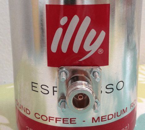
To mount the cable and attach the antenna itself, I used the F-connector. 
I drilled a central contact at the connector. 
I screwed the connector to the mast. 
I cleaned the central core of the cable of the required length. 
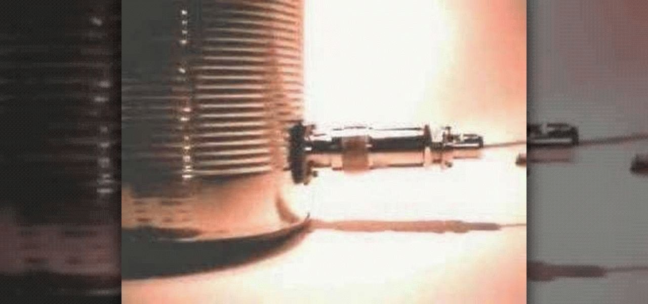
I drilled a hole in the can. 
Assembled the antenna


And painted with nitro enamel from a spray can.

Now about testing antennas in real conditions.
I already wrote about the first antenna. Its radius was about 20-30 meters.
The connection was checked between the D-Link DIR-300 router and a tablet computer to access Internet pages
and video calling via Skype from two points. 
The first point was located at a distance of 240 m from the antenna,
At a distance of 450 m, Internet access was at a speed of 1 Mb / s, but the video call via Skype was constantly interrupted.
The can antenna performed better than the helical antenna.
At a distance of 450m, Skype video calling was satisfactory. The conclusion I made is that the antenna from the can has a narrower radiation pattern and is good for creating a connection with remote users.
But for this you need to "target" the very user. The spiral antenna has a wider diagram, so the connection is possible without careful "aiming".
As for the distance, I connected to the Internet via a tablet computer, and they have built-in Wi-Fi antennas with a small gain, therefore, the distance is short.
Those. I get a good signal from the router, but when I connect, I can't get an IP address and the connection is broken. I basically achieved the desired results. 450 m is more than enough for me.
But for those who need a greater communication distance, my suggestions will be as follows: put the same external antennas on both sides,
both from the side of the router or access point and from the side of the network adapter, and install a more powerful access point such as SENAO ECB-8610S or EnGenius ECB-3500.
Their output power is six times that of conventional routers, but the price is five to six times more expensive.
We decided to make an antenna for WiFi ... There are many options, netizens are looking for new ways. Probably because there are myriad situations in life, each solution is powerless to lay out the network. Today we propose to consider a couple of methods for improving reception / transmission. Atypical solutions will be considered, the design process of Kharchenko's antenna has been described many times. According to the designer's idea, dated the 70s of the last century, in a modernized version. Do you want to make a WiFi antenna yourself? Better read the review further! Let's get started.
Increase WiFi antenna gain
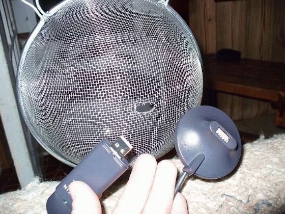
With the help of beer cans, you will assemble an antenna for receiving the MV range (the ubiquitous First Channel), an excellent reflector of an arbitrary frequency. A parabolic surface has one interesting property:
Beams coming from any direction are reflected and collected by the focal plane. If you aim the product at the broadcasting point, the lines will intersect in focus.
The Internet was flooded with modifications to factory modems, antennas in order to obtain additional amplification. Without paying a penny. Consider saving techniques. Most external WiFi modem antennas are omnidirectional. In the factory modem, antennas 2-3 (often inside) can be divided as follows:
- External / internal antenna.
- The presence of several internal antennas.
- Multiple outdoor antennas.
It is clear that most modems are standard, the uninitiated ask the question: what gives the number of antennas? The answer is simple: better reception and transmission. The communication adopted vertical polarization. The vector rotates, the signal disappears altogether. An antenna with circular polarization will fix the matter, it will receive no worse, it will not fall into dependence on the direction of the electric field.
Homemade antenna
Today, two surfaces are of interest:
- A paraboloid of revolution is obtained if the ordinary graph Y \u003d X 2 is rotated around the axis of symmetry (in this case, the ordinate). The rays coming from the side of the concave part will be collected by the focal plane. Using the principle, satellite dishes work. If you take a ready-made, arbitrary radius, make something similar with your own hands from paper, epoxy resin, foil, you get a sensible device to enhance reception.
- In the case of whip antennas, a fold surface can be used. A purchased sheet of thin steel is adjusted according to the pattern - let's talk below. The method is widely discussed on the Internet, instead of a parabola, a semicircle is used, tin is taken from a beer can. Minus is visible: two lines coincide approximately at the very beginning of the abscissa axis. Accurate focusing is not possible and the gain drops.
Let's see why the WiFi antenna starts to receive better when fenced off with a reflector. In a YouTube video, ValeraZik says: some of the pins, being covered from one side with the palm, receive better (any channel), part of the radiation is reflected by the hand. Not true. If you take a kung fu master (the path of the blocking fist), the hand will be like a steel hand, the hand of other people, as well as a shuitsa, is unable to reflect anything.

The hand extinguishes radiation coming from other directions. Artificial interference, natural sources. As a result, the quality of the signal increases inexorably. Sometimes noticeable with the naked ear, in the case of long antennas it may not play a role.
Let's imagine using the example of human hearing. Lor is quietly talking numbers, trying to hear them, they are constantly chatting at the other end of the room. For example, a partition fenced off from interference, a sound insulator wall, of course, the necessary information will be perceived more clearly. If the hand is replaced with a metal grounded shield, the situation will change radically. The wall reflects unnecessary waves back, useful information will be concentrated at the right point. Of course, if you choose the right shape envelope.
Using a parabolic WiFi transmit / receive antenna
It happens that the points of broadcasting, receiving in line of sight, are significantly removed. Firstly, factory, home-made log-periodic antennas, wave channels will come in handy, and they act witty. WiFi at 5 GHz coincides with the frequency of the satellite broadcasting range C. There is a topic at forumru.tele-satinfo.ru/index.php?topic\u003d70121.0, it shows how to convert the converter from receiving to transmitting a signal. Of course, the experiment is not for beginners, but, having received a successful alignment, we catch the broadcast of space, all the more we will accept it from the Earth.

Now let's remember that it is the C range that is less afraid of fogs, rains, and other whims of nature. It is necessary to organize a bi-directional channel. There is a lot about the receiving part, it is written in detail here cqham.ru/ao40_equip.htm. It is proposed to subordinate the MMDS converters to the fishing goals (cable broadcasting on the air, it is not possible to lay the network underground, on the surface). The difference with WiFi in the range is 100 MHz, the author at the specified link discusses how to properly convert MMDS converters to WiFi. In more detail, a slightly different problem is being solved, for our case the solution is suitable (in the review, the author is trying to establish a connection at the WiFi frequency with the AO-40 radio amateur satellite).
The topic of a bidirectional channel is discussed. A helical antenna is used for transmission, the construction of which (with your own hands) was discussed in the section. Equally are the nuances of the directional diagram of the device. From the text of the article it can be seen: the factory plate is suitable for the purposes of reception. Suitable for complementing the functionality of the already standing one (NTV +). Discussed how to properly adapt WiFi equipment. Let us briefly recall that there is no need to touch the dish itself, just based on the laws of optics (the angle of incidence is equal to the angle of reflection), estimate at what point in the focal plane the WiFi modem and antenna will be located.

Mini antenna equipped with a reflector
A swarm of converters stuck around a multifeed, add a receiver there. The orbit is projected onto the focal plane along one large-diameter arc, the location of the best WiFi reception depends on the coordinates of the transmitter, relative to the dish.
We understand that links to forums are unable to act as a reliable source. Firstly, readers can search Yandex, how to properly perform technological operations, and secondly, they can ask the administrator to post a topic. Then we will do the work. We hope the readers understood, realized the possibility of using satellite equipment for terrestrial communication (MMDS).
Make a beer can screen for a WiFi antenna
Sometimes making an antenna for WiFi with your own hands is not the best option, it's easier to re-equip an existing one. Consider a common case of limiting the broadcast area of \u200b\u200ban access point. Covering some of the WiFi antennas with your hand will improve the reception quality, you won't be sitting all year round! For those wishing to solve the problem, we provide the name of the program - Inssider. A signal level meter with which you can find the best antenna, create a suitable screen, aim the device in azimuth. Actually, start with this, then design / buy.
ZikValera in the video demonstrates a comparison of antennas, factory and own assembly. Those who want to spend 20 minutes on contemplation, we send to watch, and we bring to the rest: the directional biquadrat, the non-directional “clover” with versatile polarization, shows itself better. The best factory model can be appreciated. But it's not about making a directional WiFi antenna. We want to show you how to improve the existing ones using simple methods.
How to make an antenna for WiFi yourself, modify it to improve quality. Make a beer screen from the can, put the pin in focus. It is easier to do, if you are too lazy to write out the equation of an ellipse from analytical geometry, place the antenna in the focus of the figure. ZikValera tried to do it optically by eye. I considered the focus to be the position at which the antenna's reflection “spreads out” to the maximum along the inside of the can. The authors presented a scientific approach. We add that in visual assessment you need to look from afar - so that the lines of sight are parallel to each other - this is how the wave front behaves in real reception. So you can make the omnidirectional WiFi antenna directional, at the same time raise the gain.
Any antediluvian equipment turns into the right one with a skillful approach. It's funny to see landfills littered with plastic window frames. The picture shows the inability of society to fully use resources.
Setting up Wi-Fi networks demonstrates a lot of nuances. Faced trying to share the Internet with home users. One computer is connected to the ISP via a cable. An access point mode is created, a security protocol and a password are selected. Home users use the Internet in parallel. The technique is hamstrung, thanks to the provider using the private line. The exit is located. The obstacles that stand between people and high-speed Internet are powerless to prevent a home-made Wi-Fi antenna from improving signal reception and transmission, the communication range and speed naturally increase.
Purpose of homemade Wi-Fi antennas
Antennas adorn many devices. Let's list:
- The tablet.
- IPhone.
- Laptops.
- Wi-Fi modems.
- Wi-Fi routers, access points.
- Cellular towers.
A homemade antenna for a Wi-Fi adapter will expand the capabilities of electronics. The access point is characterized by the ability to transmit a signal omnidirectional. Power spreads out, filling the azimuths. Supplementing the access point with a special external purchased, homemade antenna, it can impart directional properties to radiation. Will increase the range of confident reception in the selected azimuth.
Put off breaking smartphones by connecting an external antenna, assemble it yourself for an access point. Most of the antennas sold in shops have a circular radiation pattern, emit the same omnidirectional power, dividing the power in azimuth.
Powerful home-made Wi-Fi antennas have a much smaller field of view, and in some cases will provide more reliable reception. Devices equipped with a reflector are equipped with a directional pattern with one central lobe. Remove the reflector - you get an eight. There will be a dead zone in the plane of the emitter location, there is no signal. A homemade antenna for a Wi-Fi router is unable to receive from the direction. The access point installation scheme is as follows:
- The device is connected to the computer (mains).
- The channel is selected.
- Full power tuning in progress.
- The type of protocol is selected.
- Password and network name are set.
The peoples are happy with the new available point. Let's take a closer look at the process, take a little time to tackle the soldering iron, pliers. Like a transmitter, an electronic device, an antenna, a router have a certain peak in the middle of the range. For example, 2.4 GHz often has 14 channels. The power of the transmitted signal is higher in the middle, for example, the sixth channel. Although each line occupies 22 MHz in the spectrum, the measurement is made at a field level of 0.707 (√2 / 2) maximum on both sides of the carrier frequency.
For reference. Determined by the type of modulation, sometimes only pilot, one band remains. Rectangular pulses, computer signals just like that, have a pronounced maximum, a bunch of side lobes. As a result, the spectrum width of the real signal is equal to infinity. The cyclic voltage band is limited, to which the process emitted by the Wi-Fi protocol does not come close.
A homemade omni-directional Wi-Fi antenna is not the best option. Nothing will change. A home-made directional Wi-Fi antenna is better, we will make it from wire, foil PCB, copper tube. Sensitive like that. The transmitted, received power is concentrated in a narrow sector. It will improve the quality of the transmission by carefully positioning users, the access point. How important the arrangement is, judge from one curious case:
- The office called the foreman. They said: in the period 12.00 - 14.00, the access point collapses. The technician took out a special device for estimating the occupied frequencies and began research. Similar programs are provided by Android OS smartphones. Use by choosing a channel before installation. Conduct research throughout the day for several days in a row, avoiding the incident. We finish what the master has discovered: the next office, separated by a wall, has painted lunch. The workers took turns using the microwave (uses the 2.4 GHz frequency). Poor insulation of household appliances, lack of grounding allowed the radiation to expose a narrow-band interference at the frequency of the magnetron. The solution to the problem turned out to be simple: the access point was moved to the opposite end of the office.
You have at hand the simplest home-made Wi-Fi antenna from a beer can with a reflector, the heroes might not know that there is a powerful source of harmful radiation nearby. The reflector gives the access point directionality, extinguishes the radiation coming from behind the wall. Another plus of directional antennas, which we will do today. By the way, when buying a microwave, try to define safety. It is necessary to plug the device into a grounded outlet, put a cell phone in the working compartment, close the door, dial the number. The signal passes - harmful radiation of the magnetron will come out. Avoid sitting next to you. Let's discuss how to make a homemade Wi-Fi antenna.
DIY directional Wi-Fi antenna
You will need tools:
- Soldering iron (solder, rosin, stand).
- Pliers.
- Small flat screwdriver.
- Vernier caliper, ruler.
- Drill with a drill for a copper tube.
Materials required:
- A piece of foil double-sided PCB as a reflector.
- Copper wire with a diameter of 1.2 mm and a length of 30 cm (only 26 cm are needed).
- The RK-50 cable is not too long so as not to extinguish the signal.
- A piece of copper tube 10 cm long so that the cable RK-50 goes inside.
Let's start with a copper tube. We cut one end by 1.5 mm, removing two thirds of the wall. An antenna will be soldered to the remaining piece. Create a biquadratic contour with a side of 30.5 mm from the wire. The size is selected from the condition for setting the 2.4 GHz band.
Likewise, any horizontal or vertical polarized signal antenna can be manufactured. Including television. A homemade Wi-Fi antenna is suitable for a tablet, phone, modem. If you know where to connect.
Please note that the side of the squares is given according to the middle section of the wire. Between the nearest edges there will be 30.5 - 1.2 \u003d 29.3 mm. You can use it. We begin to bend, finding the middle. We use the edge of the ruler as a support, we determine the state when the cut begins to balance. We make a bend by 90 degrees, this will be the point where the central core of the RK-50 will connect. We bend the wire, getting a "square eight", both ends must return strictly symmetrically. We cut it off, a couple of millimeters before the initial bend. Tinkering the ends, put the figure eight aside.
We mark the middle of the PCB, drill a hole so that the copper tube barely fits. We play both sides. We take a copper tube, tin the outer edge of the thin wall left by the first step. The figure eight is 1.5 cm away from the reflector. Lud the tube in a circle, with a rim at the specified distance from the edge (excluding the thin wall). We solder the tube to the board, preferably at a 90 degree angle. We put both ends of the figure eight on a thin wall so that the initial bend does not touch the tube. We orientate the eights parallel to the larger side of the PCB at a distance of 1.5 cm. The reflector is now grounded.
The RK-50 cable is pulled inward, the screen is mounted on a copper tube, and the core is placed on the initial bend of the figure eight. We mount the connector on the opposite end, just solder the cut to the necessary contacts of the modem, phone, or any other device. We start the test. Figure 8 must be set vertically for horizontal polarization. If it works, we find a silicone sealant that is not afraid of frost, precipitation, fill in the place where the cable exits to the antenna with a good layer. Once solidified, the antenna will successfully withstand rain.
If we replace the wire with a thick conductor PV1 of a sufficiently large section (2.5 mm 2), we will clean the braid at the point of the initial bend and at the ends. Homemade laptop Wi-Fi antenna will be weatherproof. Today shrink materials are produced. The heated film tightly wraps the product, protecting it from the vagaries of bad weather.