Very often, in the process of technical creativity, it is necessary to produce printed circuit boards for mounting electronic circuits. And now I will tell you about one of the most, in my opinion, advanced ways of manufacturing printed circuit boards using a laser printer and an iron. We live in the 21st century, so we will facilitate our work using a computer.
Step 1. Board design
We will design the printed circuit board in a specialized program. For example, in the sprint Layout 4.

Step 2. Printing the board drawing
After that we need to print the board drawing. To do this, let's do the following:
- In the printer settings, turn off all options for saving toner, and if there is a corresponding regulator, set the maximum saturation.
- Let's take an A4 sheet from some unnecessary magazine. The paper should be coated and preferably a minimum of drawing on it.
- Let's print a printed circuit board drawing on coated paper in a mirror image. Better in several copies at once.

Step 3. Stripping the board
Let's put the printed sheet aside for now and start preparing the board. Foil-clad getinax, foil-clad textolite can serve as a source material for the board. When stored for a long time, copper foil becomes covered with a film of oxides, which can interfere with etching. So let's start preparing the board. Peel off the oxide film from the board with fine sandpaper. Do not be too zealous, the foil is thin. Ideally, the board should be shiny after stripping.

Step 4. Degreasing the board
After stripping, we rinse the board with running water. After that, you need to degrease the board in order for the toner to adhere better. You can degrease with any household detergent, or by washing with an organic solvent (for example, gasoline or acetone)

Step 5. Transferring the drawing to the board
After that, with the help of an iron, we transfer the drawing from sheet to board. Put the printout with a pattern on the board and start ironing with a hot iron, evenly warming up the entire board. The toner will begin to melt and adhere to the board. The time and effort of heating is selected experimentally. It is necessary that the toner does not spread, but it also needs to be welded all over.

Step 6. Cleaning the board from paper
After the board with the paper stuck to it has cooled down, we will wet it and roll it under the stream of water with our fingers. Wet paper will collect into spools, and adhering toner will remain in place. The toner is strong enough and is difficult to scrape off with a fingernail.

Step 7. Etching the board
Etching of printed circuit boards is best done in ferric chloride (III) Fe Cl 3. This reagent is sold in any radio parts store and is inexpensive. We immerse the board in the solution and wait. The etching process depends on the freshness of the solution, its concentration, etc. It can take from 10 minutes to an hour or more. The process can be accelerated by shaking the bath with the solution.

The end of the process is determined visually - when all unprotected copper has been vented.

The toner is washed off with acetone.

Step 8. Drilling holes
The image of the parts has been transferred to the board, greatly simplifies assembly
Once I came across a video on the Internet on applying inscriptions on various surfaces using acrylic varnish. The essence there is simple, you print the inscription on a laser printer, coat it with varnish on the front side, wait for the varnish to dry, then soak the paper in warm water, carefully roll it into lumps and remove it from the dried varnish, when all the paper is removed, then only a transparent layer of varnish will remain with toner adhered to it in the form of your lettering.
But the varnish is very fragile and it is difficult to remove the paper from it without damaging it. And then the idea came to use ordinary tape instead of varnish!
Methodology
We print the inscription, glue transparent adhesive tape on the front side, iron it well, cut off the excess with scissors, and under the tap with warm water. The paper is removed very easily, but you should not rub it hard so as not to damage the toner layer, and when it seems that the adhesive tape is perfectly cleaned of paper, then carefully look again for the presence of paper residues, because small residues of paper in water are practically transparent and invisible.After removing the paper, there are 2 options for gluing the tape:
1. We glue immediately, without waiting for the water to dry. This makes it possible to peel off the tape several times to correct the position of the inscription.
2. Place the tape sticky side up and wait for the water to dry. To speed up drying, a bath coil or a battery in winter works well. Oddly enough, the stickiness is restored completely. You need to glue it right immediately, because dried scotch tape is difficult to peel off without damaging the inscription.
The adhesive tape remains sticky only where there is no toner! The paper is ordinary office paper.
Here are some examples of what happens:
I printed a scale into the ammeter, an inscription under the voltmeter, and + -, this is the first test on a good old experimental power supply unit. 
Printed circuit boards with laser printer
Method one.
Ingredients:
Aluminum foil.
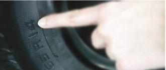
Bought at a hardware store. There are two types of foil: thick soft and thin hard. Thick foil, probably, is made only by us, but thin foil can be both ours and imported. In this, only the thin one is needed. It has one side mirrored and the other matte. If you cut a 1 x 10 cm strip of such a foil and try to hold it horizontally at one end, the strip will bend under its own weight. If the foil is thick, it will not bend under such conditions. In new packaging, the thin foil usually has a scalloped edge on the sheet and the roll is sealed in transparent film.
Laser printer.I used HP LJ 6L, but probably any will do. It is necessary to turn off all economic modes, make the printer make the drawing darker, i.e. use up more toner. It is advisable to run the paper through the printer so that it is less curled. From this point of view, the first models of the HP LJ are probably better, it seemed like it was possible to skip the paper almost without bending at all. But it is also normal to release paper to the bottom exit. Electric iron. We put the thermostat on one point (synthetics), and we begin to conduct experiments for fine adjustment. The iron should not melt the laser-printed image immediately. That is, toner at this temperature should turn from solid to viscous, but not liquid. Self-adhesive labels for printing on them with a laser printer. In principle, you can replace them with something else, but I feel sorry for the printer (see below). Rubber sheet. As smooth as possible, preferably soft. I used ~ 5mm foam rubber with a smooth (non-porous) top layer. Now we take a sheet of plain paper that your printer is printing on. We put on it a slightly smaller piece of foil, matte side up, and carefully, but evenly, glue it on one short side with strips cut from the self-adhesive stickers. You cannot glue it with tape, because the printer has a stove on which the tape will remain. The sticky surface should naturally not protrude beyond the edges of the paper. Now we load this structure into the printer so that the glued edge of the foil goes first, and we force the printer to drag this sheet (print a text file from one space :). I find it very difficult to spoil a printer with foil. Well, if only because there is a lot of chalk in the paper for which it is designed, but it is quite hard. Well, you can hammer the printer with foil in the same way as with paper. Therefore, the foil must be glued firmly, evenly, so that no folds are formed. Well, there should be no gaps along the edges. The sheet of foil that came out of the printer has obvious stripes from any wheels with which the printer pulls the paper. Remember where these stripes are located, these places will be inoperative, you cannot make an accurate drawing on them. Maybe something rude will work out, but I didn't need it. Now we need the actual drawing of the future board. In anything, practically. If it is a bitmap, there will be problems with the exact dimensions, the pixels will be visible, etc., but it is possible in principle. With vector formats (* .wmf, for example), only scale is hassle. Most of all I love AutoCAD, it is easy to draw in it, the dimensions are always accurate, etc. The unaltered places (tracks) should be black, and do not forget that the drawing on the board will be mirrored in relation to the drawing. The board should be surrounded by a 2mm wide track, which is bad but protects the rest of the board. But along this path it is convenient to cut the board later. It may be easiest to draw the board on a large sheet of paper to scale and scan it. We fill a sheet of paper into the printer and display our drawing. We make sure that it is in the correct scale and in the right place on the sheet. Now we make another design from a sheet of paper, foil and an adhesive strip, with the difference that now we know where the drawing will be, and a small piece of foil is needed. There must be clean paper under the foil, otherwise the back side of the foil will stick to the paper. We print the board drawing and examine it carefully. Surely somewhere there was a marriage due to uneven foil, specks, etc., in this case it is better to print everything again, on a new piece of foil. If the whole design is gone and stretched, you probably printed it not on the matte, but on the smooth side of the foil. Well, when everything works out correctly and efficiently, carefully cut off the foil from the paper. Now we put a sheet of rubber on some heat-resistant surface, on it with a foil pattern upwards, and cover it with a piece of carefully cleaned foil-clad fiberglass, with the foil down. We put a hot iron on top, and press it with something heavy. I used a 16 kg pack of ceramic tiles :) After 5 minutes, carefully remove the iron, but put something cold and heavy in its place, but with a flat bottom surface. I put the same pack of tiles. After 10 minutes, the structure will finally cool down, then we poison the fiberglass with the foil adhered to it. Thin aluminum foil is etched in ferric chloride very quickly, leaving, however, some rags that prevent copper from etching normally. Therefore, the board needs to be rinsed with water, at the same time you can look at the quality of the resulting drawing, and if necessary, retouch. If the tracks are greased, you have inaccurately removed the iron or put a cold load. If there are no tracks somewhere, the iron is too cold, or the gas released during etching of aluminum tore off the aluminum along with the paint. If the tracks become wide the iron is too hot, or the board has been heating for too long. Well, after etching, you will have a one-sided board. How to synchronize the drawing on the second side, if you need it, I don't know yet. It's easier to make two boards, and glue them back together. The accuracy I got is 0.3 mm, although this is not accuracy, but somehow it is called differently. Tracks or spaces between them already (stress on the first syllable) 0.3 mm are obtained with difficulty. For example, I made a small board with SOIC "and with different numbers of legs and chip elements, and the accuracy turned out to be quite sufficient.
Method two.
I have an even easier way of making boards with a pitch of 1.25 mm, paper with some kind of shiny coating is used as a carrier, it is sold in stores on a par with a regular office one, in such gray unsightly packs of 250 sheets. It is quite thin, one side looks like a coated one, and this side is a little shiny. Heat shrinkage, of course, is, but acceptable. So here, I spread scarves on OrCad PCB 4.42 (386 +), you can immediately print from it to any HP LaserJet (there are options for a mirror, negative, etc.), but I print to a file (300DPI), and then I transform it into PCX with the HP2PCX lotion (it was included in PaintBrusH 4.5), and then I compose a sheet of several shawls with any graph. editor (I like Paint SNop Pro under VIN95) Next - the usual printing process (I prefer the same PB4.5 - simple and one to one) on a shiny layer, one pass is enough, if the board is double-sided, both sides should be on the same sheet to avoid strong mismatch due to different shrinkage of the paper. By the way, if you drive it out with a clean sheet on a laser before printing, then this glitch tends to zero. Then the fat-free board is laid with copper up on a flat surface, on top of the imprint face down. This is all pressed with an iron heated to the temperature of ironing the crepe de Chine (ask the ladies), you can first through a thin dry cotton fabric, and then you can gently smooth the paper until the toner adheres to the board, then it does not lag behind. Then the board cools down, it needs to be lowered into water heated to about 40C, held there for a couple of minutes (it will be seen how the paper will turn sour), everything will be easily pulled off, the rest just roll with your finger. Due to the coating, there will be no lint on the board, as with ordinary paper, when the board dries, you can see that a whitish coating from the paper remains on top of the toner layer. If the board is double-sided, then at first both sides of the paper are aligned to the light, in any free opposite places two technological holes are pricked with a needle, the first side of the board is "ironed" as usual, then drilled according to those. otv. with a thin drill, and on the other hand along them to the light is combined with a piece of paper of the other side, which can be fixed, and then just as "smooth" as the first side, there will be no harm to the opposite side. Naturally, soak the board when both sides are already ironed. All this was etched and FeCl3, and a hodgepodge with hydroperite without problems. All this was checked even on the getinax, there are no delamination of the tracks. After etching the drill, OrCad set it up so that when printing inside the pads, there are unpainted points, which after etching will be instead of punching. As a result, a line with a width of 1 pixel at 300DPI was obtained, of course, it was a little wider, but the fact is obvious. I heard that people used fluoroplastic film instead of paper, but did not say where to get it.
Method three
Need to:
Iron...
I use a regular old electric iron with a thermostat, I put the regulator on "flax" .. A laser printer or xer _with one-component toner. HP LJ3P and LJ4L have been tested with complete success, nothing happened with QMS and Mita copiers - the toner layer is very thin. When printing from Windows, I set the contrast to maximum, while the toner layer is easily felt with a finger. I have not tried with refilled cartridges, although according to my observations they sometimes give an even thicker layer of toner ... Fine sandpaper, refined gasoline or acetone for degreasing ... Paper ... I use sheets from Stereo & Video magazine. There is very thin coated paper. The ink doesn't get in the way. I also tried it on ordinary calendered paper, but it turns out disgusting ... The Finnish chalk (~ 80 g / m) seems to fit, but it gets soaked too slowly ...
Process:
A mirrored inverted board drawing is printed on a thin chalkboard. Fiberglass is cut to fit the size of the board with margins of at least a centimeter on each side and cleaned with a circular motion with sandpaper. The main task is to cover the entire surface of the copper with micro-scratches, so that it appears as if matte. After sanding, degrease in the most thorough way, and at the same time remove all dust, even from scratches ... Glass fiber laminate is placed with copper on the toner and the paper is wrapped and fixed with adhesive tape so that it does not slide off when welding. You need a slight tension, but it is harmful to overtighten ... Sometimes it is useful to wrap the resulting sandwich with another sheet of writing paper in order to reduce the likelihood that the toner paper will "run" under the iron. Place the card with the toner side up. A heated iron is placed on it with a plane for 20-30 seconds so that the fiberglass is warmed up ... Then the edge of the iron with moderate pressure (here you need to fill your hand experimentally) carefully passes the entire surface several times. If you squeeze, the toner spreads to the sides and the drawing turns out to be smeared, if you do not press it, it may not stick ... It takes me about 2-3 minutes on a 10x10 cm board ... After it has cooled down, the board is put in warm water for 20 minutes. 30, after which the soaked paper is easily removed, leaving the toner on the board and the chalk layer on the toner. If the paper is soggy and has left tatters, you can roll them under the water with the pad of your finger. A normally adhered toner is hard to grieve even with a fingernail, so if something falls off under your finger, it means that it is underheated or undershot in step 5 ... 8-) The chalk layer on the surface of the toner acts as an additional mask that closes the pores in the toner, but if you do not soak, then it can also close the holes for subsequent drilling (I always make them, because this then eliminates the need for nibbling). It dries without heating, the toner tends to fall off if a wet board is dried under a lamp or on a battery ... Imprints are painted on with an indelible marker. It is useful to take all the available ones in advance, draw strips with them on an unnecessary piece of fiberglass and throw them into ferric chloride. About half of the markers I have come across with a characteristic smell of something like toluene are good for this. In any case, they hold for 5 minutes, if you do not rub ... BTW: my imprints appear at most on one board out of 10 ... 8-) If the chalk layer somewhere covered the holes (on a dry board it can be seen perfectly) - you can neatly remove from them with a needle ... It is etched in a heated solution of ferric chloride. The solution should be sufficiently concentrated, I fill one volumetric part of the crystals by eye with two parts of hot (60-70 degrees) boiled water and, after complete dissolution, filter ... I have never done a temperature above 50 degrees, already at 40-50 it takes only several minutes, and with a hotter solution, the toner may float. It is undesirable to rub the board with a cotton swab, it is better to shake it, but you need to make sure that no air bubbles remain on the surface ... After etching, the toner is removed with something (I used a nail polish remover or a Flux-Off aerosol which began to appear regularly on the market in Mitino ). After that, it is drilled, cut and so on, as usual ... Checked, it works. If ferric chloride is not shrunk, then it is almost never etched. Tracks already 0.5mm may not work, I usually do around 0.8mm. I simply did not try to make double-sided boards - it was not very necessary, although I do not exclude that with a certain accuracy and careful alignment of the sheets in the gap before inserting the PCB between them, they will be made ... narrow strips of double-sided tape in the margins?)
Method four
I don’t know (but would like) if my development is original, see: HP LaserJet 5L (6L etc) toner is a meltable polymer ex. soluble in acetone (etc.) Reflected layout, printed on paper with IRON, was fused to a copper board. The paper was dissolved in sulfuric acid. Etched with iron trichloride. The remaining toner was washed with solvent. The best result is that the toner was printed at 98%, under the picture in some places 3% of a total of 95% escaped without loss of sharpness.
Details:
Method five (laser-acetone)
Sent to the conference Sergey Kovalev E-Mail: [email protected]
Everything is like in laser-ironing technology, except for the iron.
Usually two or three experiences are enough to master this technology. In general, it is noticeably less capricious than the traditional ironing one.
HOW TO MANUFACTURE A PCB UNDER THE INDUSTRIAL
Abramov Sergey, Orenburg.
mailto: [email protected]
For the manufacture of a printed circuit board, it is better to use one-sided fiberglass. This, of course, complicates the layout of the tracks, but it is convenient in the case of making a board by thermal transfer. If the paths are badly routed by the router, then you can put the jumpers on the side of the parts. This way we get rid of the problem of aligning layers, in the case of double-sided routing. So, having drawn the board in any editor (ACCEL 15 is convenient), we set the laser printer to the maximum toner output and print on coated paper (for example, advertising brochures in a radio magazine, etc. - printing ink does not interfere) or thermal paper from a fax in advance glued on a standard sheet, with the sensitive layer outward. Then we apply it to the glass fiber laminate, previously sanded with zero toner to the foil and smooth it with an iron for about a minute (it depends on the size of the board). The iron is set to maximum. If the toner is smeared, reduce the ironing time and repeat the operation. After that, they are placed under a stream of warm water and soaked for 15-20 minutes. Then rub the paper with your fingers like a rubber band, leaving the toner. The adhesion and acid resistance of the toner make it possible to etch in almost any known solution and get a board in quality that is not inferior to the industrial one. It is better to print on paper from the program on which the board is billed. In particular, ACCEL 15 is very convenient, it allows you to output tracks 1: 1, as well as invert and unfold if necessary.
The method of manufacturing single printed circuit boards with the transfer of a pattern from a printout on a laser printer is gaining more and more popularity among radio amateurs. It is best to print on thin coated paper - there is less nap in it, good results are obtained on the sheets of the Stereo & Video magazine, as well as self-adhesive substrates and thermal paper for faxes (choose the side experimentally). In laser printers, turn on the maximum toner supply mode (turn off the "economy" mode if it was on, contrast to maximum, etc.), and also use the path with the minimum paper bend (this option is available in older models of HP LJ 2 , LJ4, etc.). The board drawing must be "mirrored", this option is available in the print menu of many graphics programs, for example Corel Draw, Corel Photo Paint, and when printing from programs that cannot "mirror", it is necessary to apply output to Postscript printers, which have a mirroring option in the driver. Instead of output to a laser printer, you can use photocopying, but also in the maximum contrast mode and on thermal paper from faxes. In the manufacture of two-layer printed circuit boards, to reduce the heat shrinkage of the paper, it is recommended to "run" the latter through the printer without printing an image before printing an image. In addition, both sides should be on the same sheet to avoid strong mismatch due to different shrinkage of the paper. The degreased board is placed with copper up on a flat surface, on top of the printed toner down. This "sandwich" from the side of the paper is pressed with an iron (for 20 - 30 seconds) heated to the temperature of ironing the crepe de Chine (ask the ladies). The iron should not melt the laser-printed image immediately. That is, toner at this temperature should turn from solid to viscous, but not liquid. When the board cools down, it must be immersed in warm water and held there for several minutes. As the paper becomes limp (it will be seen), everything will easily peel off, the rest just roll up with your finger. Instead of water, you can remove the paper with sulfuric acid. If the tracks are greased, you have inadvertently removed the iron or placed a cold load. If the tracks are missing somewhere, the iron is too cold. If the tracks become wide, the iron is too hot, or the board has been heating for too long. If the board is double-sided, then first, paper printouts of both sides are aligned to the light, two technological holes are pierced with a needle in any free opposite places, the first side of the board is "ironed" as usual, then drilled through the technological holes with a thin drill, and on the other side along them on the gap aligns with the paper print on the other side. You can poison with ferric chloride (to speed up it a little), and a hodgepodge with hydroprite. All this was applied even on the getinax, there are no delamination of the tracks, tracks up to 0.8 mm wide are normally performed, and with some experience up to 0.5 mm. After etching, the toner is removed with acetone, nail polish remover or Flux Off. Drilled, trimmed and so on as usual ... Another way to apply a picture to p / p using a laser printer. Making p / p using a laser printer and an iron is a rather tedious process, but gives a pretty good result if you practice a little. 1. Gently glue a sheet of fax paper (glossy side up) onto a sheet of plain paper (to compensate for the lack of hardness in faxing). What for? It is necessary to first drive the paper through the printer / laser fuser - for shrinkage. For quiet dragging through the c / z path, it is enough to simply iron the thermal paper with an iron from the sensitive side. 2. Paper - take a base from self-adhesive, or thermal paper for a fax is definitely thermal paper, and prepared - first, iron the sheets with a hot iron until they are flat (at the same time they will turn dark brown, then bluish gray), fold them in this form for future use ... Before removing the board, drive the sheet through the printer - for example, by printing a blank page. minimum sheet size - ~ 6 * 12 cm for HP 5 / 6L. 3. Print - at maximum fat content, mirror image. printing and transfer to a workpiece can be up to a week apart, I have not tried it again (this is for those who do not have a laser at home). 4. Take the workpiece with a 3-5 mm margin on each side. foil - lightly sand with zero and wipe. there should not be any harmful deposits such as white sediment from denatured alcohol. I use isopropyl alcohol or gasoline "galosh" (aka "for lighters"). 5. Iron - with a normal, smooth surface. warm up in advance. Temperature - for waxing, you need to carefully select (I have a display meter for "isk.silk"), otherwise the impregnation will begin to transfer. for thermal paper - it can be higher. 6. Dust and all sorts of little things - should not be, neither on foil, nor on paper. 7. Make a sandwich - put a piece of thick cardboard, a blank board, blow off the dust, a drawing, for thermal paper (it is thin) - also a piece of moderately thick paper, a hot iron on flat thick plywood (though I have 3 mm paper). 8. You begin to crawl with an iron, pressing with a force of ~ 5..10 kg / sq.dm. crawl about two minutes to grab. 9. Tilting the iron very slightly, roll individual tracks for a couple of minutes. It is very important here not to crush the tracks, and at the same time to weld them. From time to time, you need to lower the iron to the entire plane so that the rest does not cool down. The thermal paper clearly shows the difference in welded and defective pieces. 10. Well, another minute you stroke to clear your conscience and remove the iron. The sandwich cools down and the paper swells between the lanes. We do not wait for cooling, the board is immediately under a stream of boiling water. 11. Now the board - under running water and a piece of wet foam rubber you start to wash the paper. It cannot be peeled off in large pieces or from dry foil. It is necessary to remove the wads of paper from the foam rubber more often. We take the paper by the corner and tear it off. Then remove the remnants with your finger / rag / foam rubber. 12. With a new piece of sponge you erase the pile (as far as possible), look at the wet drawing under a magnifying glass. if there are a lot of defects, or they are located in inconvenient places - see item 1, with variation of parameters. 13. Seal the reverse side with strips of wide adhesive tape, poison. Even in boiling FeCl3
The simplest, most affordable and giving good results method of making printed circuit boards at home is the so-called "laser-iron" (or LUT). The description of this method can be easily found by the corresponding keywords, so we will not dwell on it in detail, just note that in the simplest version all that is needed is access to a laser printer and the most ordinary iron (not counting the usual materials for etching boards). So, there are no alternatives to this method?
While developing various electronic devices, used, for example, in testing monitors, we used several methods of mounting electronic components. At the same time, printed circuit boards were not always used as such, since when creating prototypes and devices in a single copy (and often it turned out to be both), subject to inevitable errors and modifications, it is often more profitable and more convenient to use factory-made breadboards, performing wiring with a thin stranded wire in Teflon insulation. Even the most famous companies do this, as demonstrated by the prototype of Sony's AIBO toy robot.

The stores sell relatively cheap double-sided tinned and even with plated holes and a protective mask on the jumpers, breadboards of very high quality.

Note that such breadboards allow you to easily achieve a high mounting density, since there is no need to worry about the wiring of the conductive tracks. However, for example, when developing power blocks and when using elements with a non-standard lead pitch or their geometry, as well as when using elements with surface mounting (which we are not doing yet), it becomes difficult to use ready-made breadboards.
As an alternative to prototyping boards, we used the methods of cutting the foil in the gaps between the conductive pads and the mentioned LUT method. The first method is applicable only in the case of the simplest layout options, but it does not require anything at all, except for a sharp knife and a ruler. The LUT method gave generally good results, but I wanted some variety. We considered the method using it too laborious and requiring the use of corrosive chemicals, which is not always acceptable at home. The case allowed us to learn about another method - the method of direct inkjet printing of a template on foil-coated fiberglass (keywords for searching in English - Direct to PCB Inkjet Printing).
The method is subdivided into the following stages:
- The actual print pigmented
- Thermal curing of the printed template. In this case, the ink becomes resistant to the etching solution.
- Removing ink from a printed circuit board.
There is also an alternative option:
- Printing in principle any ink the printed circuit board template directly on the foil-coated fiberglass using, as a rule, a modified inkjet printer.
- Powder toner from the laser printer / copier is sprayed onto the ink that is still wet and the excess toner is removed.
- Thermal curing of the printed template. This fuses the toner and adheres securely to the foil.
- Etching of unprotected foil areas using a conventional method, for example, using iron III chloride.
- Removing caked toner from the circuit board.
We did not consider the second option due to the reluctance to work with powder toner, which can stain everything around in case of accidental wrong movement or sneezing. Epson inkjet printers were used in all the implemented methods of direct inkjet printing of the template that we found. Also, the type of ink, or rather the type of dye used in them - a pigment, is consistently associated with the printers of this manufacturer, so we started the search for a suitable printer from the Epson catalog. Apparently, Epson has, or at least had models capable of printing on media with a thickness of up to 2.4 mm (and not only on CDs / DVDs), for example, the Epson Stylus Photo R800, but this the model is no longer produced, but we did not know in advance whether it would be possible to use something from modern analogues (obviously expensive). As a result, it was decided to look for the cheapest model that uses pigment ink. The model was found - Epson Stylus S22. This printer turned out to be the cheapest among all Epson printers - the price for it was less than 1,500 rubles, but then, however, it grew noticeably: in Moscow retail (the ruble equivalent - in the pop-up tip) - N / A (0).

A quick inspection showed the need to make significant changes to the design of the printer, since it involved printing on flexible media with its bend when moving from the top loading tray to the receiving tray. The sequential modification described below was synthesized from several iterations, since after the next assembly it became clear that certain changes had to be made to the design. Therefore, the possibility of small inaccuracies in the description of this process is not excluded. The modification has two main goals. First, to ensure a straight line without bends and differences in heights, the supply of the media, for which you need to change, and in fact re-create the feeding and receiving trays. Secondly, to ensure the ability to print on thick materials - up to 2 mm, for which it is necessary to raise the assembly with the print head and its guides. So:
1. Unscrew the two self-tapping screws on the rear wall and remove the casing, releasing the latches with which it still clings to the bottom.

2. Disconnect the control panel cable from the main board, unscrew the two self-tapping screws securing the control panel,

release the control panel cable and set it aside. It still comes in handy, unlike the case casing.
3. Unscrew the 4 self-tapping screws of the paper feed unit, release the wires going to the carriage motor, depress the feed roller gear lock, remove the feed roller stand and the entire feed unit, remove the side paper clamp - these parts are no longer useful.


4. Unscrew the self-tapping screws on the pallet of the absorbent pad and on the power supply, disconnect the drain hose from the pallet and the cable from the PSU on the main board, remove the pallet of the absorbent pad and PSU. Putting them aside will come in handy.


5. Unscrew the two self-tapping screws of the strip with the rollers pressing the outgoing sheet, remove this assembly and move it into a pile with "extra" parts.

6. On the right, unscrew the self-tapping screw and the screw securing the slide along which the print head moves.

Remove the slide holding spring.

Remove the spring of the carriage ruler (streaked strips) and the ruler itself.

Remove the two screws holding the main board

and push it away from the slide (be careful with the paper sensor!). Unscrew the self-tapping screw for securing the slide, located under the main board.

On the left, unscrew the self-tapping screw for fastening the slide.

Disconnect the feed motor connector (J7) from the main board.

Disconnect the spring on the left side of the slide.

Remove the slide assembly with print carriage and main board.

7. On the left, unscrew the screw of the broach shaft retainer,

remove the shaft and its retainer.

8. Remove all additional guides at the beginning of the broach, which are attached to the clips.

9. Using a blade from a hacksaw and file files, cut out a window in the bottom from the side posts, to the bottom of the feed chute and to the feed shaft. In this case, it is convenient to use the existing grooves and holes in the bottom. Cut off burrs with a knife, remove sawdust.

10. Now you need to create the Direct Feed Tray. To do this, you can use two pieces of an aluminum corner 10 x 10 mm, 250 mm long and part of the original paper support in the input tray (you can use any rigid plate of a suitable size). The corners are fixed with M3 countersunk screws as shown in the photos below. On the vertical planes of the printer body, to which the corners are attached, cut grooves so that the input tray can be slightly moved up and down to fine-tune its position.


At the right corner, you need to cut the vertical corner, otherwise the right pressure roller will rest against it. Also, on the pallet, you need to cut a groove opposite the paper sensor (although, apparently, you can not do this).

And put a piece of the tube on the antenna of the paper sensor, thereby slightly lengthening it.

11. Disconnect the feed shaft position sensor (one screw), cut off the stopper on the sensor housing, and fix it by sliding it down as far as possible.

When reassembling, make sure that the disc with stripes is placed in the middle of the sensor slot and does not touch its edges.
12. Under the three attachment points of the slide, place the two washers with a hole of 4 mm, each 1 mm thick. When using wide washers in two places, they must be sawed off so that they do not rest against the body elements.


13. Remove the pressure rollers, put on them 2-3 layers (at least 3 layers on the central pair of rollers) of the heat-shrink tube with the shrinkage of the intermediate layers with a hot air gun or other heating method. Use a file to deepen the grooves for the rollers so that they rotate freely. Insert the rollers into the holders.

14. In the parked position, as well as in the process of cleaning the nozzles and initializing new cartridges, a pad with a rubber pad is pressed against the bottom surface of the print head, where the nozzles are located. A tube leading to the vacuum pump is connected to the bottom of the pillow. When cleaning, the pump sucks ink from the cartridges, and during storage, the nozzles are protected from drying out the ink in them. Therefore, it is important to ensure a snug fit of the rubber gasket to the head, but due to the upward movement of the slide and the print head, this condition may not be met. It is necessary to increase the travel of the pillow in the crib. To do this, you will have to remove or at least move the pump away - unscrew the two screws and squeeze out the two latches.


Then remove the spring that tightens the cushion bed, remove the bed-cushion assembly, and disconnect the tubing extending from the cushion. Then, with a knife, cut by about 1.5 mm in the right places the sections of the body of the pillow and the bed, increasing the vertical stroke of the pillow. Then put the knot back together. Since when using non-original cartridges, automatic cleaning of nozzles and initialization of cartridges led to strange results, we decided to disconnect the pump from the pad, for which we used a piece of tubing and a tee. To remove excess ink or when manually flushing the pad, you can connect a syringe to the tee, or simply pinch its outlet with your finger and, turning the feed shaft back (behind the gear in front of the left), activate the printer pump.
15. Assemble the printer in reverse order. When installing the feed shaft, carefully clean the seats of chips and dust and apply a layer of grease to them and the corresponding areas of the shaft. After installing the shaft, you need to adjust the feed tray. Having loosened the screws securing the tray to the side walls of the case, using a rigid plate of a suitable size (for example, a piece of fiberglass), it is necessary to ensure that the movement of the plate from the supply tray along the supply shaft and along the shaft in the output tray is even, without differences in height. Also, ensure that the feed chute guides are perfectly parallel and perpendicular to the feed shaft. Having found such a position of the feeding tray, the screws should be tightened and, preferably, fixed on the side of the nuts with a drop of varnish. Then continue building. On the right side, due to the sliding of the slide up, or rather, the mounting hole will not coincide with the hole in the housing post - you can file the hole and fix the slide with a screw, or you can leave it as it is.

After shortening its right leg, we installed the tray of the absorbent pad in its original place, fixing it at two points with hot melt glue. The power supply did not fit in its original position, so we did not find anything better than to simply fix it with a plastic tie on the left stand of the printer frame. We screwed the control panel to the ear on the power supply unit.


The original output tray causes the output sheet to bend, so it needs to be improved to ensure a smooth horizontal output of the sheet. To do this, it is enough to put something a little less than 3 cm high under the tray, and put a couple of thick magazines or a stack of paper on the tray. However, after a while we replaced this design with a tray made from the casing of an inoperative DVD player. What needs to be done with the casing to turn it into a tray is clear from the photos, however, here everyone can use their imagination and available material.


Result:


Move the slide up by b abouta larger value than described above is fraught with some difficulties. The problem areas are at least the feed shaft position sensor, the right bracket of the carriage ruler, and the parking assembly. Maybe something else. As a result, the thickness of the material on which the modified printer can print is about 2 mm or a little more, therefore, with a textolite with a thickness of 1.5 mm, the substrate should not be thicker than 0.5 mm, while it must be stiff enough to move blanks for printed circuit boards. A suitable and affordable material turned out to be thick cardboard, for example, from a folder for papers. The liner must be cut exactly to the width of the input tray, as any horizontal offset will affect print accuracy. In our case, the substrate is 216.5 x 295 mm. The original feed unit cannot be used, so the liner must be manually fed under the pressure rollers, but the paper sensor must not be activated. Because of what, in the substrate you will have to make a cutout for the antenna of the paper sensor, in our case at a distance of 65 mm from the right edge, 40 mm deep and 10 mm wide. In this case, printing begins at a distance of 6 mm from the bottom of the cutout, that is, 6 mm before the edge of the media that the printer detects. Why this is so - we do not know. It is convenient to use double-sided adhesive tape to secure the workpieces to the substrate. The pinch rollers press the liner against the feed roller with great force, so the rollers must not slide in or out of the workpiece for a smooth feed during printing. To ensure this condition, before, after and possibly from the sides of the workpiece, material with the same thickness must be glued. It will also make it easier to position the workpiece for serial and / or duplex printing.
The original cartridges ran out pretty quickly, but overall the results using the original ink were quite good... However, it was decided to purchase refillable cartridges and compatible inks.


The soul did not rest on this, attempts were made to modify the ink in order to increase the content of the polymer component in them. As a result of these experiments, nozzles with black ink clogged by 90%, with magenta - by 50%, in the "yellow" row one nozzle did not work and only cyan ink nozzles remained fully functional. However, one color is enough to print templates. Since magenta ink performed the best, it was the cyan ink that was loaded into the cyan cartridge.
1. Prepare the surface of the workpiece. If it is relatively clean, then degreasing it with acetone is sufficient. Otherwise, degrease, clean with an abrasive sponge, and, to form an oxide layer, place in the oven for 15-20 minutes at a temperature of 180 ° C. Then cool and degrease with acetone.
2. Using double-sided adhesive tape and auxiliary pieces of textolite, fix the workpiece on the substrate.
3. Convert the template to a solid color that will be used for printing. In our case - in blue (RGB \u003d 0, 255, 255). Carry out a test print (not the entire template, but only the overall points, for example, corners), if necessary, in the program used for printing, correct the position of the template, wash off the previous result with acetone, and repeat the correction procedure, if necessary.

4. Print the template on the blank. Best results are obtained with the following settings:


5. Air-dry the workpiece for 5 minutes, you can use a hair dryer to speed up. Then detach the workpiece from the substrate and carry out preliminary fixing in the oven for 15 minutes (time from turning on the oven) at 200 ° C at its peak. Cool the workpiece.
6. For precise positioning of the second layer, you can drill several holes of small diameter, for example, 1 mm in diameter at the mounting points of the future board. Fasten the workpiece with the surface for the second layer upwards, while the double-sided adhesive tape must be glued to the completely painted areas of the first layer. If the workpiece is tightly clamped between the two plates at the front and back, it is not necessary to use double-sided tape. Degrease the workpiece with acetone.
7. Perform positioning and printing - repeat steps 3 and 4.

8. Air-dry the workpiece for 5 minutes; you can use a hair dryer to speed up. Then detach the workpiece from the substrate, fix it on racks, for example, made of paper clips, place it in the oven, and fix it for 15 minutes (time from turning on the stove) at 210 ° C at its peak. Cool the workpiece.


9. Inspect the workpiece, paint over places with a suspiciously thin layer of ink (for example, near holes or adhered dust) with a waterproof marker. Etch the workpiece. To keep the surface of the workpiece at a distance from the bottom of the container, you can insert toothpicks into the holes (1 mm in diameter, used to position the second layer), so that the sharp tip protrudes 1.5-2 mm, and the thick one bites off to the same height. When etching, periodically turn the board over and check its readiness.


Wash off ink with acetone.


Important notes.
1. In order for the ink used to acquire resistance to the etching solution, it must be kept for about 15 minutes (time from turning on the stove) at a temperature of about 210 ° C at its peak (obtained using a thermocouple located next to the workpiece). The interval is narrow, since when the textolite is exceeded by 5-10 ° C, the textolite begins to collapse, if it is underestimated, the ink is washed off with an etching solution. The exact conditions in a particular case must be selected empirically. You can use a cotton swab test for control. If a cotton swab moistened with water can easily wash off the ink, then you need to increase the temperature, if it does not wash off, or only slightly stains, then resistance to the etching solution has been acquired. Even if a cotton swab moistened with acetone can hardly wash off the ink, it means that the resistance to the etching solution is very good. This way you can select the ink and curing conditions that give the best results. Note that we used an electric grill stove, turned on only the upper heating element, and when the ink was finally fixed, the stove thermostat was set at 220 ° C.
2. The reproducibility of printing reaches about 0.1 mm, therefore, if necessary, you can print it a second time over the first side of the template, with intermediate drying directly on the substrate with a hot air gun (with adjustable temperature) or a household hair dryer set to the maximum temperature. Drying is necessary so that the pressure rollers do not lubricate the previous layer.
3. The production of the two sides can be done sequentially. First print and secure the first side, and protect the foil on the second, for example, with acrylic paint from a can. Etch the first side, rinse off the protection from the second with acetone, print and secure the second side, paint on the first, etch the second side, and wash off the protection from the first.
4. You need to print as follows: first send a print job, wait until the printer informs about the lack of paper, then carefully push the substrate with the fixed blank under the pressure rollers, scrolling the feed shaft behind the gear in front of the left, and then press the continue printing button. For short breaks between printing sessions, the printer will not perform a short cleaning procedure, so you can first load the liner with a blank and then send the print job.
5. Be extremely clean, as any speck of dust that gets on the wet ink on the workpiece may cause a defect.
In this way, several double-sided printed circuit boards were made, and although the tracks athowever, than 0.5 mm was not used, in the test sections the possibility of obtaining tracks with a width of 0.25 mm was demonstrated, and this is clearly not the limit of this method.

P.S. An example of a double-sided board with 0.25 mm tracks (during the design, the norms of 0.25 mm were laid for the width of the tracks and for the gaps, but with manual finishing the distances between the tracks were increased as much as possible). Note that in the manufacture of double-sided boards, apparently, it is still more reliable to print and etch the sides sequentially. Side 1:

Side 2:

Three types of defects can be noticed:
1. Linear distortion, which is apparently caused by the fact that one side was printed in fast two pass mode, and the other in slow one pass mode. That is, it is better to print both sides in the same mode.
2. In some places the tracks are slightly broadened due to ink spreading. This defect can be avoided by thoroughly preparing the surface - degrease with a piece of cloth soaked in acetone, then wipe thoroughly with a dry cotton swab.
3. From one edge of the track and contact pads bleed much more. This happened due to overheating, as a result of which the ink darkened and began to flake off. This means that it is necessary to carefully monitor the uniformity of heating (choose a place in the oven where the heating is more uniform) and in no case should it overheat - the ink should darken noticeably, but not acquire a dark gray tint.
However, these defects were not critical and as a result, without any wiring correction, we got a fully functioning device.