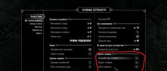
Ambilight technology
The proprietary backlighting technology of the aforementioned company is a special lamp built into the TV that allows you to project a soft glow onto the wall behind the TV in a certain way, which, as it were, continues the picture from the screen to increase immersion in the atmosphere of what is happening on the screen.
The technology itself was born in the last century due to the fact that, on the one hand, the brightness of the then TV receivers was insufficient, and the audience turned off the lights when watching them, on the other hand, watching TV in the dark gave a sharp strain on the eyes, which led to rapid fatigue and general discomfort. The solution was obvious - the presence of a source of diffused light nearby (the so-called TV lamps). Today, according to Philips research department, this problem designed to solve the technology "Ambilight".
At the moment, there are already 5 generations (and a lot of modifications) of this technology, of which the last three are the most common:
- Three-channel backlight technology Ambilight Surround» with additional lamps on top of the body to expand the field of effects upwards and independent binding of the left, right and top block of background lamps to the corresponding area of the screen.
- full backlight technology Ambilight Full Surround”, where the screen is already surrounded by lamps on all sides. Accordingly, the processor responsible for controlling the lamps builds background image on the analysis of at least four areas of the image on the screen. For the best transfer light, the TV case is equipped with a rear screen-panel.
- Technology " Ambilight Spectra”, which allows you to create a “volumetric” image thanks to more than 120 new generation LEDs and advanced image processing algorithms.
All technologies create, to some extent, ambient light behind the TV that complements the colors and light intensity of the image displayed on the screen.
What can be said at the end of the review? The device is undoubtedly interesting and worth trying, especially considering that the manufacturer provides a free test drive for 30 days, i.e. if you don’t like the device, you can return it and get your money back. Your costs in this case will be equal to the postage to the manufacturer. The main disadvantage is that the device works only in conjunction with software, which means that a computer is needed to get the effect of dynamic backlighting.
Results
Well, in the dry residue we have:
pros
- work with any type of monitors and TV connected to the computer;
- low system requirements to the PC hardware;
- fully implemented functionality that does not differ from that declared by the manufacturer;
- good software support, including third-party software vendors;
- the possibility of individual configuration of the product and the creation of non-standard solutions;
- low price;
- ample opportunities for payment and delivery of goods;
- ease of installation and configuration;
- Russian speaking service technical support;
- detailed text and video instructions on the manufacturer's website;
- free test drive.
Minuses
- you need a computer to get the dynamic backlight effect;
- lack of software in the delivery, the need to download it from the Internet;
- the lack of instructions in the kit (even electronic), the need to read it on the manufacturer's website;
- lack of a number of fastening elements (double-sided adhesive tape) for LEDs;
- the need for a certain location of the screen (15-30 cm from the wall) to obtain the most correct effect;
- absence warranty card and details of the manufacturer both on the packaging and on the product itself.
Philips in 2007 patented an incredibly simple, but, without exaggeration, amazing TV backlight technology. With such adaptive backlight, eyes get tired less when viewing in the dark, the effect of presence increases, the display area expands, etc. Ambilight is applicable not only to video and photo content, but also to games. Ambilight has become a business card Philips TVs. Since then, Philips has been closely vigilant that none of the major manufacturers would even dare to encroach on the sacred by creating something like this. Probably, it is possible to license this technology, but the conditions are somehow prohibitive, and other market players are not particularly eager to do this. Smaller companies also tried (and there are now companies that do) to implement similar technology in the form of separate kits, but punishment from Philips was inevitable. So in the best case, if the company does not somehow renew the patent or its derivative, other manufacturers will be able to produce something similar only in 2027.
But we, ordinary consumers, are not affected by such punishment. We are free to do what we think is right for ourselves. Today I will tell you in detail how to independently make adaptive background lighting for a TV or monitor like Philips Ambilight (hereinafter simply Ambilight). For some, the article will not contain anything new, because. there are dozens of such projects, and hundreds of articles have been written in different languages, and there are thousands of people who have already done the same for themselves. But for many, this can all be very interesting. You don't need any special skills. Only basic knowledge of physics for the 8th grade of high school. Well, quite a bit of soldering wires.
To better understand what I'm talking about, I will give my own example of what happened. Real costs for TV 42 "- about 1000 rubles and 2 hours of work.
The video does not convey all the sensations and the effect as a whole, but for the first time the children sat with their mouths open.
Possible Implementations
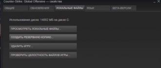
There are several variations of Ambilight implementation options. They depend on the video source.The cheapest, easiest and most effective option - the signal source is a Windows PC, Mac OS X or Linux. Now Windows-boxes on Atom processors are very common, which cost from $70. All of them are ideal for implementing Ambilight. I've been using various Windows boxes (in my TV cabinet) as a media player for several years, wrote a small bunch of reviews and consider them to be the best set-top boxes for media content. The hardware implementation of this option is the same for all of the listed operating systems. It is about this option that I will discuss in the article.. The software part will be Windows system, AmbiBox will act as a universal control program. With Mac OS X and Linux you can use .
The second option - the media set-top box on Android based, of which there are also many. This option is the most problematic. First, the backlight will only work in the Kodi media combiner (and forks of this project). Secondly, in the overwhelming majority of cases, everything works only with disabled hardware video decoding, which is unacceptable for most boxes. The hardware implementation of the project also imposes certain requirements. I will not touch on it, but if something specific interests me, I will try to answer in the comments.
The third option is a source-independent solution. This is the most expensive, but absolutely one-stop solution, because the signal is picked up directly from HDMI cable. For it, you will need a fairly powerful microcomputer (such as Raspberry Pi), an HDMI splitter (splitter), an HDMI-RCA AV converter, a USB 2.0 analog video capture device. Only with this option will you be able to use Ambilight with any set-top box/receiver, Android boxes, Apple TV, game consoles(for example, Xbox One, PlayStation 4), etc. devices that have HDMI output. For the version with 1080p60 support, the cost of components (without LED strip) will be about $70, with support for 2160p60 - about $100. This option is very interesting, but you need to write a separate article on it.
Hardware
To implement, you will need three main components: a controllable RGB LED strip, a power supply, and an Arduino microcomputer.First, a few explanations.
WS2811 is a three-channel controller/driver (chip) for RGB LEDs with single-wire control (addressing to arbitrary LED). The WS2812B is an RGB LED in an SMD 5050 package that already has a built-in WS2811 controller.
For simplicity, suitable LED strips for the project are called WS2811 or WS2812B.
The WS2812B strip is a strip with WS2812B LEDs in series. The tape works with a voltage of 5 V. There are tapes with different LED densities. Usually it is: 144, 90, 74, 60, 30 per meter. There are different degrees of protection. Most often it is: IP20-30 (protection against ingress of solid particles), IP65 (protection against dust and water jets), IP67 (protection against dust and protection against partial or short-term immersion in water to a depth of 1 m). Black and white lining.
Here is an example of such a tape:

A WS2811 tape is a tape on which a WS2811 controller and some kind of RGB LED are placed in series. There are options designed for voltages of 5 V and 12 V. Density and protection are similar to the previous version.
Here is an example of such a tape:

There are also WS2811 "ribbons" with large and powerful LEDs, as in the photo below. They are also suitable for implementing Ambilight for some huge panel.

Which ribbon to choose, WS2812B and WS2811?
Important factor- feed the tape, which I will talk about a little later.
If you have a suitable power supply at home (often power supplies remain at home from old or damaged equipment), then choose a tape based on the voltage of the power supply, i.e. 5V - WS2812B, 12V - WS2811. In this case, you will simply save money.
From myself I can give a recommendation. If the total number of LEDs in the system is no more than 120, then WS2812B. If more than 120, then WS2811 with an operating voltage of 12 V. Why exactly, you will understand when it comes to connecting the tape to the power supply.
What level of tape protection should I choose?
For most, IP65 will do. it is coated with “silicone” (epoxy) on one side and has a 3M self-adhesive surface on the other. It is convenient to mount this tape on a TV or monitor and it is convenient to wipe it from dust.
What density of LEDs to choose?
For the project, ribbons with a density of 30 to 60 LEDs per meter are suitable (of course, 144 is possible, no one forbids). The higher the density, the greater the Ambilight resolution (number of zones) and the greater the maximum overall brightness. But it should be borne in mind that the more LEDs in the project, the more complex the tape power circuit will be, and a more powerful power supply will be needed. Maximum amount LEDs in the project - 300.
Buying a Tape
If your TV or monitor is hanging on the wall, and all 4 sides have a lot of free space nearby, then the tape is best placed at the back around the perimeter on all 4 sides for maximum effect. If your TV or monitor is installed on a stand, or there is not enough free space below, then the tape should be placed on the back on 3 sides (i.e. bottom without tape).
For myself, I chose a white tape WS2812B IP65 with 30 LEDs per meter. I already had a suitable 5 V power supply. I decided 60 or 30 LEDs per meter, but chose the latter after reviewing the video with ready-made implementation examples - the brightness and resolution suited me, and the power supply is easier to organize, fewer wires. Aliexpress has a huge number of lots of WS2812B tapes. I ordered 5 meters for $16. For my TV (42", 3 sides) I needed only 2 meters, i.e. you could buy for $ 10, the remaining three meters for a friend. Prices often change with sellers, there are a lot of offers, so just choose a cheap lot on Aliexpress with a high rating keywords search - WS2812B IP65 go WS2811 12V IP65).


Buying a Power Supply for the Tape
The power supply is selected by power and voltage. For WS2812B - voltage 5 V. For WS2811 - 5 or 12 V. The maximum power consumption of one WS2812B LED is 0.3 W. For WS2811 in most cases the same. Those. the power of the power supply must be at least N * 0.3 W, where N is the number of LEDs in the project.
For example, you have a 42" TV, you settled on a WS2812B tape with 30 LEDs per meter, you need 3 meters of tape on all 4 sides. You will need a power supply with a voltage of 5 V and a maximum power of 0.3 * 30 * 3 = 27 W , i.e. 5 V / 6 A. In my implementation, only 3 sides are used, a total of 60 LEDs (to be precise, then 57) - power from 18 W, i.e. 5 V / 4 A.
I have long been idle multiport USB charger ORICO CSA-5U (8 A), left over from the old review. It has parallel power to the ports (this is critically important), this memory is ideal for me as a power supply unit, because. I will connect the tape through 2 parallel connections (explanations will be a little later in the article).

If I didn’t have this memory, then I would choose (there is information that it is in this PSU that the insides are put at 2.5 A, so you need to study this issue in more detail with the seller, or look at other models).

Buying a microcomputer
Ambilight will be controlled by an Arduino microcomputer. Arduino Nano on Aliexpress costs about a piece.

Costs for my option (for TV 42"):
$10 - 2 meters WS2812B IP65 (30 LEDs per meter)
$ 4 - power supply 5 V / 4 A (I did not spend money on the PSU, I quote the cost for clarity)
$2.5 - Arduino Nano
-----------
16,5$
or 1000 rubles
Hardware Implementation
The most important thing is to properly organize the feed of the tape. The tape is long, the voltage sags at high current, especially at 5 V. Most of the problems that arise for those who make themselves Ambilight are related to power. I use a rule - you need to make a separate power supply for every 10 W of maximum power consumption at 5 V and 25 W of power consumption at 12 V. The length of the power supply (from the power supply to the tape itself) should be minimal (without a margin), especially at 5 V.
The general connection diagram is as follows (the diagram shows the power connection for my version):

Power is supplied to the tape at both ends - two parallel connections. For example, if I were lighting on all 4 sides, and the tape was 60 LEDs per meter (i.e. maximum power 54 W), then I would make the following power supply:

The supply wires must be used appropriately, the smaller the caliber (AWG), the better, so that they are enough with a margin for the calculated current strength.
There are two pins going to the Arduino from the tape. GND to be connected to the corresponding pin on the Arduino. And DATA, which must be connected to the sixth digital pin through a 300-550 Ohm resistor (470 Ohm is better). If you do not have a resistor, then in most cases everything will work fine without it, but it is better to have one. The resistor can be bought for a couple of cents at any radio shop. The Arduino microcomputer itself can be placed in any convenient case, many use the Kinder surprise egg for this. The Arduino should be placed as close to the tape as possible so that the DATA lead is as short as possible.
Soldering the wires to the tape is easy. The main rule is that the contact time with the soldering iron should be minimal;
In my case it turned out like this:


Two black quality USB cable went for power, and white for connecting to a computer. I ran out of white heat shrink tubing, I used red ones. Not so "beautiful", but it suits me (it's hidden behind the TV anyway).
An important question is how to bend the tape at a right angle? If you have a tape for 60 LEDs, then the tape needs to be cut and connected with short wires (placing all this in a heat shrink tube). You can buy special corner connectors for three pins for LED strips (there are 4 pins in the picture, just for example):

If you have a strip of 30 LEDs, then the distance between the LEDs is large, you can easily make a corner without cutting. Remove a piece of the “silicone” coating, isolate (even with “adhesive tape”) the contact pad and bend it according to the scheme:
I cut off a piece of tape to practice. The main thing is not to overdo it - slightly bent once and that's it. You don’t need to bend here and there, you don’t need to strongly squeeze the bend line.

Here is a rear view of the TV, all the wires go through the hole inside the cabinet:

Software part
This is the simplest.We connect the Arduino microcomputer via USB. The driver (CH340 serial interface) will install automatically. If this does not happen, then in the Arduino IDE folder there is Drivers folder with everything you need.
Launch the Arduino IDE and open the Adalight.ino file.

Change the number of LEDs in the code. I have 57.

Tools > Board > Arduino nano
Tools > Port > Select COM port (there will be the right option)
Click the "Download" button:

The program will inform you when the download is complete (it's literally a couple of seconds).
Ready. Disconnect Arduino from USB and reconnect. The ribbon will turn red, green and blue in sequence - the Arduino is activated and ready to go.
Download and install the program. In the program, click "More settings" and specify the device - Adalight, COM port and the number of LEDs. Choose the number of frames to capture (up to 60).

Next, click Show Capture Zones > Zone Wizard. Choose your ribbon configuration.

Click Apply and Save Settings. On this basic settings are running out. Then you can experiment with the size of the capture zones, make color correction of the tape, etc. The program has many different settings.

To activate a profile, just double-click on the corresponding icon (AmbiBox profiles) in the Windows notification area. The tape will light up immediately. Turns off too double tap.
That's basically it. You saw the result at the beginning of the article. Nothing complicated, cheap and cool. I am sure that you will do better, so share your crafts in the comments.
TVs with dynamic backlighting around the display frame are one of Philips' signature features. And unlike many others, it works. However, everything comes at a price, and TVs with Ambilight and increased immersive effect are more expensive than many other models.
Russian developers have proposed a method that will allow equipping monitors of any manufacturer with dynamic backlighting. To do this, you do not even have to take the device to service center A: It only takes a little time and perseverance.
In general, such a backlight can be purchased in the form of radio components and configured independently. But, as practice shows, this is almost comparable to ready-made options from PaintPack.
Two basic models are offered: a monitor version (30 LEDs) and a TV version (60 LEDs). There is also a very simple one - for 10 LEDs, but it is only suitable for the smallest monitors.
The TV version is equipped with an external power supply. Also, a larger number of LEDs speaks in its favor, which gives a large backlight area (it will glow wider and higher, in other words). If these options are not suitable for any reason, you can contact the developers: for a small surcharge, they will offer a modified version.
mindrunway.comPaintPack, in fact, is a small case to which removable LED strips are connected on both sides. The box with the filling carries indicators and a power connector, as well as microUSB for connecting to a PC. There is also a master connector (proprietary) for serial connection of two devices.
The body of the device is placed on the back of the TV or monitor. Then LED strips are laid in accordance with the instructions, power is connected and witchcraft begins. When connecting PaintPack to a computer via a USB connector, you need to install drivers and configure the device in the bundled program.
 mysku.ru
 Configuration is done using the AmbiBox package. You need to go to the "Smart backlight" menu, select the screen capture method and one of the operating modes offered in the program:
- Static background - any color is set, the glow of the LEDs is regulated.
- Color music - the backlight will flash in time with the sound of the music. The backlight color is set to green-yellow.
- Dynamic background - a smooth flow of one color into another.
- Screen capture is the main mode of operation.
In this mode, you can capture color from the movies and games you are watching. The backlight color will change according to the image on the screen, divided into top, bottom and side zones (each separately).
PaintPack works a little slower than official analogue from Philips. But given the difference in cost and the ability to upgrade any device, the choice is obvious.
With backlight.
The option proposed below differs from those already considered in that the backlight turns on automatically, does not require changes to the design of the TV and can work as an emergency lighting.
Of the shortcomings, it should be noted that the backlight is static, it takes time to install and configure for specific equipment.
Formulation of the problem
So, we need a backlight that turns on when the room is dark enough and the TV is on, it burns half-heartedly when the TV does not work, but the room is very dark and someone is walking on it. In all other cases, the backlight should be off. Restrictions: the equipment is under warranty - you can’t climb inside.Solution
To determine the mode of operation of the TV, we will use this thing:TAK12-02 High-frequency Pulse Current Transformer
The device allows, by inserting one of the power wires into the hole, to remove the induced current from the contacts, and by its value to draw a conclusion about the mode of operation of the TV. Suppose that for a TV in sleep mode, the current consumption will be significantly lower than in active mode. Illumination will be measured with a photoresistor, also known as LDR, movement around the room will be fixed using PIR, everything will be controlled by arduino. The scheme turned out like this:

Backlight connection diagram
Implementation
The backlight is led strip glued to the plastic corner. While he just lies behind the TV, then I will screw it to the wall.
Backlight

Ready device
After the first test runs, epic fail was a little disappointing for me - it turned out that the plasma TV fell asleep very hard - it could take up to half an hour to do this (see the graph below). In addition, he sleeps very anxiously, waking up every 2-3 hours for 15-20 minutes.

Panasonic TX-P50G30 goes to bed. Y-axis - current in parrots, X-axis - time in seconds x2.
All this, plus the cat on which the PIR worked, led to the fact that the “light music” worked in the living room all night. But considering that the TV is used only in tandem with the tuner, and he has fewer problems with sleep, the problem was solved, although not as beautifully as planned. It was possible to reduce the effect of kote on the system by gluing the lower part of the PIR.

Refined backlight wiring diagram

Tuner current consumption. Y-axis - current in parrots, X-axis - time in minutes.
As you can see in the picture above, the tuner, unlike the TV, immediately goes into sleep mode, which is noticeable by the decrease in current. The tuner also has moments of extreme power consumption, marked "burst" on the graph, and they can occur both in sleep and active modes. To increase the reliability of determining the operating mode, the flow of measurements was divided into series of 3 minutes, for each series the mean value (SV) and standard deviation (RMS) were considered. We took into account only the values of the series with a small standard deviation and SZ not falling into the “burst” zone. All this made it possible, with a delay, but quite accurately, to determine the mode of operation of the tuner.
Expenses:
I am not strong in circuitry, the details were taken according to the principle "what is", I will be grateful for comments and additions: 
Wiring diagram, not basic.
Sketch for arduino can be found.
conclusions
- The idea to determine the operating mode of the device by power consumption turned out to be not so good in practice. Cumbersome algorithm, significant lag in operation, the need fine tuning, make the commercial implementation of the Idea impossible, but as a hobby project, it has the right to life.
- Energy consumption statistics collected during the work gives reason to think about what the Appliances with sleep mode, especially if it is connected to the internet.

Device assembled.
Lighting at work.
update.
- Zorki noticed an error in wiring diagram thanks, corrected.
- I took into account a fair remark and slightly changed the name of the topic.
- I added a picture of a TV with a working backlight, just as an illustration of the fact that by throwing an LED strip behind the TV, you can increase the viewing comfort. I will not make a video - in my opinion it is not informative for static lighting.
- Moved to DIY, thanks for the karma.
Since the idea of controlling the consumed current is not an ideal way to determine the mode of operation of the TV, at the end of the topic I present the following table in collaboration with,, and other respected commentators.
Alternatives
| Way | Advantages | Flaws |
|---|---|---|
| Solder on the status LED | reliable, trustworthy | unsportsmanlike, you need to open the TV |
| Set FP to control the status LED | reliable, trustworthy | the front panel of the TV changes - not aesthetically pleasing |
| Catch pickups from a sweep plasma TV using an antenna placed behind the screen | cool, no need to pull the wires to the TV | research needed, suitable for plasma only |
| Control TV temperature | simplicity, reliability | delay in detection, additional wires from the sensor, possibly only suitable for plasma |
| Analyze the presence of a signal on one of the wires included in the SCART connector | simplicity, reliability | research is needed, one of the connectors will be occupied, additional wires |
| Put the FP in front of the TV and determine the glow of the screen | if you put a matrix from FP, you can organize a full-fledged ambient light | additional wires, complexity of placement, the need for an additional optical system |
| Catch an IR signal to turn on / off the TV | simplicity, minimum wires | No feedback- possible malfunctions |
| Control the presence of power on the USB port | simplicity, reliability | not suitable for all TVs, takes up a USB port, additional wires |
| Analyze the current consumed by the TV | minimum wires | complex algorithm, delay in determination, not applicable for all TVs |
Update 2.
Practice has shown that the Hall effect chip ACS712 measures the current much more accurately than the TAK12-02 transformer. Therefore, its use is preferable. 
Signal from ACS712 when measuring the current consumption of a computer. 0 corresponds to 2.5V
And the sale of the 6th Lightpack. Just the other day I received the treasured package with the latest revision of the device. In short, Lightpack is background lighting monitor or TV. There are 2 types of backlight on sale, this is the version for the monitor and the version for the TV. The TV version has a separate power supply and instead of 10 individual LEDs, 30 LEDs on strips are used. As a result, 3 diodes per channel are obtained, and due to this, the backlight area increases. I put the backlight on a 24" monitor. In the future I plan to buy a TV for movies, so I took the version for TV with a margin. A computer is a must for Lightpack!
The device is sold in a small box, to open it you need to cut a sticker with a description and a complete set. 
The whole set is packed in bubble wrap. The board is in a separate antistatic bag. 
Included:
- Lightpack 6 master board protective glass 70x70x17 mm
- 10 segments of RGB light tape (each 10 cm long and contains 3 LEDs)
- Mains power supply 110-240V (cord length 1.8 m)
- USB cable Am/Bm mini 1.8 m
- Pair of mounting posts and ties


The new controller has a nice appearance. Now it's not just open printed circuit board, and a nice transparent acrylic box. The developers do not call it a body. In fact, this is protection, curved acrylic, and inside, a board is attached to two countersunk bolts. Holes everywhere are selected in such a way that no effort is required on the nuts themselves. They are mostly decorative. Thus, access to all connectors on the board remains: USB, power, diodes and a firmware update button. Very original approach, stylish and functional. 
Mini USB and 12V power. 

New connectors for diodes have become more convenient. Now there is no need to clean and fasten anything. 
To achieve illumination around the entire monitor, I decided to hang it on the wall.
Initially, I wanted to mount the monitor on a thin mount. On the one hand, this is a plus - short distance between the wall and the monitor, but for Lightpack it turned out to be a minus. For a smoother dispersion of light, the distance between the monitor and the wall should be more than 10-15 cm. I had to install a mount that allows you to change this distance. 
Before fixing everything, we pre-calculate correct location for placing diodes. On the site in the documentation section there are many options for placing diodes. 
For the test, I fixed the diodes at the top and on the right side. On a thin mount, the distance to the wall is minimal, about 3-4 cm. The light is poorly scattered and dark voids form between the diodes. 


The diode tape has an adhesive surface. Before gluing, thoroughly clean the surface of the monitor. 
Having calculated everything along the line, I get the following configuration. 
The USB connectors on the side of the monitor mess things up a bit. But this did not affect the result. 
There are simple speakers at the bottom of the monitor. Although the diodes are located differently, the illumination is uniform. 
We lay all the wires so that nothing hangs and there is no load on the diodes. There are a lot of wires, the length of each is 70 cm, and in the version for monitors 50 cm. This kit is designed for large TVs. The 2 zip ties that come with the kit are definitely not enough. The adhesive base of the diode tape did not adhere very firmly to the monitor, possibly due to the glossy plastic. I had to tweak the design a bit. 


Via utilities testing the monitor, see what happened. 


The end result is something like this. Of course, for complete happiness, I would like to remove the cable channel with wires, but somehow I don’t want to ditch my wall. 
The controller connected to the computer is defined as a regular HID device. We install the program from the site and start setting up.
When you start the program, 10 colored digital blocks appear. Each block is a capture zone. The program analyzes a picture that falls into this zone several tens of times per second, calculates its average color and sends it to a device that already makes the corresponding block of three LEDs glow in the desired color. Blocks are capture areas. They can be moved around the screen and resized. The larger the capture area, the higher the processor load. But for movies, it's actually easier to set the dimensions in the form of narrow strips along the edges of the monitor. So zoning out 100% of the desktop is almost always useless. To heighten the effect in films, some zones should be overlapped. 
In fact, everything is very simple. By default, there are acceptable settings and you don’t have to dig into them once again. 
The Lightpack has another mode of operation, similar to Philips LivingColors lamps, the backlight will smoothly change colors at an adjustable speed or not change the selected color at all.
In games, the backlight also works, but not in all. In DirectX 9 everything is fine, but in 10 and 11 there are problems. In any case, Lightpak is being finalized Full time job: There is already a community of users and developers who are constantly solving problems and adding new features. There is an API for developers, for example, there is a plugin for Winamp, which I will show in the video at the end.
The result obtained met my expectations. Watching movies with such an effect is really nice. Immersion is certainly not 3D, but also spectacular. What can I say, watch the video.