Lecture. Processor manufacturing
Microprocessor is an integrated circuit formed on a small silicon crystal. Silicon is used in microcircuits due to the fact that it has semiconducting properties: its electrical conductivity is greater than that of dielectrics, but less than that of metals. Silicon can be made as an insulator that prevents the movement of electric charges, and as a conductor - then electric charges will pass freely through it. The conductivity of the semiconductor can be controlled by introducing impurities.
Microprocessor contains millions of transistors connected to each other by the thinnest conductors made of aluminum or copper and used for data processing. This is how the internal tires are formed. As a result, the microprocessor performs many functions - from mathematical and logical operations to controlling the operation of other microcircuits and the entire computer.
One of the main parameters of the microprocessor is the frequency of the crystal, which determines the number of operations per unit of time, the frequency of operation system bus, the amount of internal SRAM cache. The processor is marked by the frequency of the crystal. The frequency of the crystal is determined by the switching frequency of the transistors from the closed state to the open state. The ability of a transistor to switch faster is determined by the technology for manufacturing the silicon wafers from which the chips are made. The dimension of the technological process determines the size of the transistor (its thickness and gate length).
How microcircuits are made
As you know from the school physics course, in modern electronics, the main components integrated circuits are semiconductors p-type and n-type(depending on the type of conductivity). Semiconductor is a substance that surpasses dielectrics in conductivity, but is inferior to metals. Both types of semiconductors are based on silicon (Si), which in its pure form (the so-called intrinsic semiconductor) does not conduct well electricity, however, the addition (insertion) of a certain impurity into silicon makes it possible to radically change its conducting properties. There are two types of mixins: donor and acceptor.
Donor admixture leads to the formation of n-type semiconductors with electronic type of conductivity, and acceptor - to the formation of p-type semiconductors with hole type of conductivity. Contacts of p- and n-semiconductors allow you to form transistors - the main structural elements modern microcircuits. Such transistors, called CMOS transistors, can be in two basic states: open, when they conduct electric current, and closed, when they do not conduct electric current. Since CMOS transistors are the main elements of modern microcircuits, let's talk about them in more detail.
When talking about Intel processors, they often use such specific concepts as 0.13-micron technological process, and in Lately- 90nm technological process. For example, it is customary to say that the new Intel processor Pentium 4 with Northwood core is made using 0.13-micron technology, and the next generation of processors will be based on 90-nanometer technological process. What is the difference between these technological processes and how does it affect the capabilities of the processors themselves?
How a CMOS transistor works
The simplest n-type CMOS transistor has three electrodes: source, gate and drain... The transistor itself is made in a p-type semiconductor with hole conductivity, and n-type semiconductors with electronic conductivity are formed in the drain and source regions. Naturally, due to the diffusion of holes from the p-region to the n-region and the reverse diffusion of electrons from the n-region to the p-region, depleted layers (layers in which there are no major charge carriers) are formed at the boundaries of the transitions of the p- and n-regions. In the normal state, that is, when no voltage is applied to the gate, the transistor is in a "locked" state, that is, it is not able to conduct current from the source to the drain. The situation does not change, even if we apply a voltage between the drain and the source (in this case, we do not take into account the leakage currents caused by the movement under the influence of the generated electric fields of minority charge carriers, that is, holes for the n-region and electrons for the p-region).
However, if a positive potential is applied to the gate (Fig. 1), then the situation will change radically.
Rice. 1. The principle of operation of a CMOS transistor
Under the influence of the electric field of the gate, holes are pushed deep into the p-semiconductor, and electrons, on the contrary, are drawn into the region under the gate, forming an electron-enriched channel between the source and drain. When a positive voltage is applied to the gate, these electrons begin to move from source to drain. In this case, the transistor conducts current - they say that the transistor "opens". If the voltage is removed from the gate, electrons stop being drawn into the region between the source and drain, the conducting channel is destroyed and the transistor stops passing current, that is, it is "locked". Thus, by changing the voltage at the gate, you can open or turn off the transistor, in the same way as you can turn on or off a conventional toggle switch, controlling the passage of current through the circuit. This is why transistors are sometimes called electronic switches. However, unlike conventional mechanical switches, CMOS transistors are virtually inertia-free and can go from open to closed state trillions of times per second! It is this characteristic, that is, the ability of instantaneous switching, that ultimately determines the speed of the processor, which consists of tens of millions of such simplest transistors.
So, a modern integrated circuit consists of tens of millions of the simplest CMOS transistors.
Here is a picture cross section processor:

Above there is a protective metal cover, which, in addition to the protective function, also acts as a heat spreader - it is this that we liberally smear with thermal paste when we install the cooler. Under the heat spreader is the same piece of silicon that performs all the user's tasks. Even lower - a special substrate, which is needed for pinout (and to increase the area of the "legs") so that the processor can be installed in a motherboard socket.
The chip itself consists of silicon, on which there are up to 9 metallization layers (made of copper) - that is how many levels are needed so that, according to a certain law, it is possible to connect transistors located on the silicon surface (since it is simply impossible to do all this at the same level). Basically, these layers act as connecting wires, only on a much smaller scale; so that the "wires" do not short-circuit each other, they are separated by a layer of oxide (with a low dielectric constant).

Let us dwell in more detail on the process of manufacturing microcircuits, the first stage of which is the production of silicon substrates.
Step 1. Growing blanks
Step 2. Application protective film dielectric (SiO2)
Step 3. Applying the photoresist
Step 4. Lithography
Step 5. Etching
Step 6. Diffusion (ion implantation)
Step 7. Spraying and deposition
Step 8. Final stage
Advanced technologies
Logic CMOS (CMDP) inverters
Chips on complementary MOS transistors (CMOS chips) are built on the basis of MOS transistors with n- and p-channels. The same input potential turns on the n-channel transistor and turns off the p-channel transistor. When a logical unit is formed, the upper transistor is open, and the lower one is closed. As a result, no current flows through the CMOS circuit. When a logical zero is formed, the lower transistor is open, and the upper one is closed. And in this case, the current from the power supply does not flow through the microcircuit. The simplest logic element is an inverter. an inverter made on complementary MOS transistors is shown in Figure 1.
Figure 1. Schematic diagram of an inverter made on complementary MOS transistors (CMOS inverter)
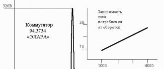
As a result of this feature of CMOS microcircuits, they have an advantage over the previously considered types - they consume current depending on the input clock frequency... An approximate graph of the dependence of the current consumption of a CMOS microcircuit, depending on the frequency of its switching, is shown in Figure 2

Figure 2. Dependence of the current consumption of a CMOS microcircuit on the frequency
Logic CMOS (CMDP) elements "AND"
Scheme of the logical element "AND-NOT" on CMOS microcircuits practically coincides with the simplified "AND" circuit on keys with electronic control which we looked at earlier. The difference is that the load is not connected to the common wire of the circuit, but to the power source. The schematic diagram of the logic element "2I-NOT", made on complementary MOS transistors (CMOS), is shown in Figure 3.

Figure 3. Schematic diagram of the logic element "2I-NOT", made on complementary MOS transistors (CMOS)
In this circuit, an ordinary one could be used in the upper arm, however, when a low signal level is formed, the circuit would constantly consume current. Instead, p-MOS transistors are used as the load. These transistors form a resistive load. If it is required to form a high potential at the output, then the transistors open, and if it is low, then they close.
In the diagram of the CMOS logic element "AND" shown in Figure 2, the current from the power supply to the output of the CMOS microcircuit will flow through one of the transistors if at least one of the inputs (or both at once) has a low potential (the logic level zero). If at both inputs of the logical CMOS element "AND" there is a level of a logical unit, then both p-MOS transistors will be closed and a low potential will form at the output of the CMOS microcircuit. In this circuit, as well as in the circuit shown in Figure 1, if the transistors of the upper arm are open, then the transistors of the lower arm will be closed, therefore, in a static state, the current will not be consumed by the CMOS microcircuit from the power supply.
Conventional graphic representation of the CMOS logic element "2I-NOT" is shown in Figure 4, and the truth table is shown in Table 1. In Table 1, inputs are designated as x 1 and x 2, and the output is F.
Figure 4. Conditional-graphic representation of the logical element "2I-NOT"
Table 1. Truth table of a CMOS microcircuit performing "2I-NOT"
| x1 | x2 | F |
|---|---|---|
| 0 | 0 | 1 |
| 0 | 1 | 1 |
| 1 | 0 | 1 |
| 1 | 1 | 0 |

Figure 5. Schematic diagram of the logical element "OR-NOT", made on complementary MOS transistors
In the CMOS logic gate "2OR-NOT", series-connected p-MOS transistors are used as a load. In it, the current from the power source to the output of the CMOS microcircuit will flow only if all the transistors in the upper arm are open, i.e. if all inputs have a low potential at once (). If at least one of the inputs has a logic-one level, then the upper arm of the push-pull stage, assembled on CMOS transistors, will be closed and the current from the power supply will not flow to the output of the CMOS microcircuit.
The truth table of the logical element "2OR-NOT", implemented by the CMOS microcircuit, is shown in Table 2, and the conventional-graphic designation of these elements is shown in Figure 6.
Figure 6. of the "2OR-NOT" element
Table 2. Truth table of the MOS microcircuit performing the logical function "2OR-NOT"
| x1 | x2 | F |
|---|---|---|
| 0 | 0 | 1 |
| 0 | 1 | 0 |
| 1 | 0 | 0 |
| 1 | 1 | 0 |
Currently, it is CMOS microcircuits that have received the greatest development. Moreover, there is a constant tendency towards a decrease in the supply voltage of these microcircuits. The first series of CMOS microcircuits, such as K1561 (foreign analogue of C4000V) had a fairly wide range of supply voltage variation (3..18V). At the same time, with a decrease in the supply voltage for a particular microcircuit, its maximum operating frequency decreases. Later, as the production technology improved, improved CMOS microcircuits with better frequency properties and lower supply voltage appeared, for example, SN74HC.
Features of the use of CMOS microcircuits
The first and main feature of CMOS microcircuits is the high input impedance of these microcircuits. As a result, any voltage can be induced at its input, including one equal to half the supply voltage, and can be stored on it for a long time. When half of the power supply is applied to the input of the CMOS element, transistors in both the upper and lower arms of the output stage open, as a result, the microcircuit begins to consume an unacceptably large current and may fail. Conclusion: the inputs of digital CMOS microcircuits must never be left unconnected!
The second feature of CMOS chips is that they can operate when the power is off. However, they often work incorrectly. This feature is related to the design of the input stage. The complete schematic diagram of a CMOS inverter is shown in Figure 7.

Figure 7. Complete schematic diagram of a CMOS inverter
Diodes VD1 and VD2 were introduced to protect the input stage from static breakdown. At the same time, when a high potential is applied to the input of the CMOS microcircuit, it will go through the VD1 diode to the microcircuit power bus, and since it consumes a fairly small current, the CMOS microcircuit will start working. However, in some cases, this current may not be enough to power the microcircuits. As a result, the CMOS chip may not work properly. Conclusion: if the CMOS microcircuit does not work properly, carefully check the power supply of the microcircuit, especially the case pins. If the negative supply terminal is poorly soldered, its potential will differ from the potential of the common wire of the circuit.
The fourth feature of CMOS microcircuits is the flow of impulse current through the power circuit when it switches from zero to single and vice versa. As a result, when switching from TTL microcircuits to CMOS analog microcircuits, the level of noise increases sharply. In some cases, this is important, and one has to abandon the use of CMOS microcircuits in favor of either BICMOS microcircuits.
CMOS logic levels
The logic levels of CMOS microcircuits differ significantly from. In the absence of load current, the voltage at the output of the CMOS microcircuit coincides with the supply voltage (logic level of one) or with the potential of the common wire (logic level of zero). With an increase in the load current, the voltage of the logical unit can decrease to 2.8V (U p = 15V) from the supply voltage. Allowable output voltage level digital CMOS microcircuits (series of microcircuits K561) with a five-volt power supply is shown in Figure 8.

Figure 8. Levels of logical signals at the output of digital CMOS microcircuits
As mentioned earlier, the voltage at the input of a digital microcircuit is usually allowed within a wide range compared to the output. For CMOS microcircuits agreed on a 30% stock. The boundaries of the logical zero and one levels for CMOS microcircuits with a five-volt power supply are shown in Figure 9.

Figure 9. Levels of logical signals at the input of digital CMOS microcircuits
When the supply voltage decreases, the boundaries of logical zero and logical unity can be determined in the same way (divide the supply voltage by 3).
CMOS families
The first CMOS microcircuits did not have protective diodes at the input, so their installation presented significant difficulties. This is a family of K172 series microcircuits. The next improved family of CMOS chips, the K176 series, received these protection diodes. It is quite widespread at the present time. The K1561 series completes the development of the first generation of CMOS microcircuits. In this family, a speed of 90 ns and a supply voltage range of 3 ... 15V were achieved. Since foreign equipment is currently widespread, I will give a foreign analogue of these CMOS microcircuits - C4000V.
A further development of CMOS microcircuits was the SN74HC series. These microcircuits have no domestic counterpart. They have a speed of 27 ns and can operate in the voltage range of 2 ... 6 V. They coincide in pinout and functional range with, but are not compatible with them in logical levels, therefore, at the same time, CMOS microcircuits of the SN74HCT series (domestic analogue - K1564) were developed, compatible with TTL microcircuits and at logic levels.
At this time, a transition to a three-volt power supply was outlined. For it, SN74ALVC CMOS microcircuits were developed with a signal delay time of 5.5 ns and a supply range of 1.65 ... 3.6 V. The same microcircuits are capable of operating with a 2.5 volt supply. In this case, the signal delay time increases to 9 ns.
The most promising family of CMOS microcircuits is currently considered to be the SN74AUC family with a signal delay time of 1.9 ns and a power supply range of 0.8 ... 2.7 V.
A specific series of microcircuits is characterized by the use of a typical electronic unit - a basic logic element. This element is the basis for the construction of a wide variety of digital electronic devices.
Below we will consider the features of the basic logical elements of various logics.
Transistor-transistor logic elements
A characteristic feature of TTL is the use of multi-emitter transistors. These transistors are designed in such a way that the individual emitters do not interfere with each other. Each emitter has its own pn junction. In the first approximation, a multi-emitter can be modeled by a diode circuit (see the dotted line in Fig. 3.27).
A simplified diagram of a TTL element is shown in Fig. 3.27. When mentally replacing a multi-emitter transistor with diodes, we get an element of diode-transistor logic "AND-NOT". From the analysis of the circuit, it can be concluded that if a low voltage level is applied to one of the inputs or to both inputs, then the base of the transistor T 2 will be zero, and the collector of the transistor T 2 will be high level voltage. If a high level is applied to both inputs, then a large base will flow through the base of T 2 of the transistor and there will be a low level on the collector of transistor T 2, that is, this element implements the NAND function:
u out = u 1 u 2. The basic element of TTL contains a multi-emitter transistor that performs a logical AND operation, and a complex inverter (Fig. 3.28). 
If a low voltage level is simultaneously applied to one or both inputs, then the multi-emitter transistor is in a saturation state and T 2 is closed, and therefore, the transistor T 4 is also closed, i.e., the output will be a high level. If a high voltage level is simultaneously acting on both inputs, then T 2 opens and enters the saturation mode, which leads to the opening and saturation of the transistor T 4 and the locking of the transistor T 3, that is, the NAND function is implemented.
To increase the speed of TTL elements, transistors with Schottky diodes (Schottky transistors) are used.
Basic logic element TTLSh (on the example of the K555 series)
The NAND element is used as the basic element of the K555 series of microcircuits. In fig. 3.29, a a diagram of this element is shown, and the conventional graphic designation is shown in Fig. 3.29, b. 
This is equivalent to the above pair of a conventional transistor and a Schottky diode. Transistor VT 4 is a conventional bipolar transistor.
If both input voltages u in1 and u in2 have a high level, then the diodes VD 3 and VD 4 are closed, transistors VT 1, VT 5 are open, and a low level voltage occurs at the output. If at least one input has a low level, then the transistors VT 1 and VT 5 are closed, and the transistors VT 3 and VT 4 are open, and there is a low level voltage at the input. It is useful to note that transistors VT 3 and VT 4 form the so-called composite (Darlington circuit).
Chips TTLSh
Chips TTLSh K555 series are characterized by the following parameters:
● power supply +5 V;
● low-level output voltage - no more than 0.4 V;
● high-level output - not less than 2.5 V;
● noise immunity - not less than 0.3 V;
● average delay time of signal propagation - 20 ns;
● the maximum operating frequency is 25 MHz.
TTLS chips are usually compatible in logic levels, noise immunity and power supply with TTL chips. The signal propagation delay time of TTLSh elements is, on average, two times less in comparison with similar TTL elements.
Features of other logics
The basis of the basic logic element of the ESL is the current switch. The circuit of the current switch (Fig. 3.30) is similar to the circuit of a differential amplifier. 
It is necessary to pay attention to the fact that ECL microcircuits are powered by negative voltage (for example, -4.5 V for the K1500 series). A negative constant is applied to the base of the transistor VT 2 reference voltage U op. Changing the input u in1 leads to a redistribution direct current i e0, given by the resistance R e between the transistors, which results in a change in the voltages on their collectors. The transistors do not enter the saturation mode, and this is one of the reasons for the high speed of the ECL elements.
Microcircuits series 100, 500 have the following parameters:
● power supply - 5.2 V;
● power consumption - 100 mW;
● branching factor at the outlet - 15;
● signal propagation delay - 2.9 ns.
In n-MOS and p-MOS microcircuits, keys are used, respectively, on n-channel MOS transistors and a dynamic load (discussed above) and on p-channel MOS transistors.
As an example, consider an n-MOS logic element that implements the OR-NOT function (Fig. 3.31). 
It consists of a load transistor T 3 and two control transistors T 1 and T 2. If both transistors T 1 and T 2 are closed, then the output is set high. If one or both voltages u 1 and u 2 have a high level, then one or both transistors T 1 and T 2 are opened and a low level is set at the output, that is, the function u out = u 1 + u 2 is implemented.
To exclude power consumption by a logical element in a static state, complementary MDP - logical elements (CMDP or CMOS logic) are used. CMOS chips use complementary MOSFET switches. They are distinguished by high noise immunity. CMOS logic is very promising. The previously considered complementary switch is actually a NOT element (inverter).
CMOS - logic element
Consider CMOS - a logical element that implements the OR-NOT function (Fig. 3.32). 
If the input voltages have low levels (u 1 and u 2 are less than the threshold voltage of the n-MOS transistor U zi.threshold n), then transistors T 1 and T 2 are closed, transistors T 3 and T 4 are open and the output voltage is high ... If one or both of the input u 1 and u 2 have a high level, exceeding U z.threshold. n, then one or both transistors T 1 and T 2 opens, and a low voltage is set between the source and the gate of one or both transistors T 3 and T 4, which leads to the blocking of one or both of the transistors T 3 and T 4, and therefore on output is set low. Thus, this element implements the function u out = u 1 + u 2 and consumes power from the power source only in short periods of time when it is switched.
Integrated injection logic (IIL or I 2 L) is based on the use of bipolar transistors and the use of original circuitry and technological solutions. It is characterized by a very economical use of the semiconductor crystal area. Elements I 2 L can be implemented only in integrated design and have no analogs in discrete circuitry.  The structure of such an element and its equivalent circuit are shown in Fig. 3.33, from which it can be seen that the transistor T 1 (p-n-p) is located horizontally, and the multi-collector T 2 (n-p n) is located vertically. T 1 plays the role of an injector, providing holes from the emitter of transistor T 1 (when a positive supply is applied to it through a limiting resistor) into the base of transistor T 2. If u 1 corresponds to the logic "0", then the injection does not flow through the base of the multicollector transistor T 2 and the currents in the collector circuits of the transistor T 2 do not flow, that is, logic "1" is set at the outputs of the transistor T 2. At a voltage u 1 corresponding to the logical "1", the injection flows through the base of the transistor T 2 and at the outputs of the transistor T 2 - logical zeros.
Consider the implementation of the OR-NOT element based on the element shown in Fig. 3.34 (for simplicity, other collectors of multicollector transistors T 3 and T 4 are not shown in the figure). When a logical signal "1" is applied to one or both inputs, then u out corresponds to a logical zero. If both inputs have logical signals "0", then the voltage u out corresponds to a logical one. 
The logic based on the semiconductor from gallium arsenide GaAs is characterized by the highest speed, which is a consequence of the high mobility of electrons (3 ... 6 times more in comparison with silicon). GaAs microcircuits can operate at frequencies of the order of 10 GHz or more.

A prime example of how complex and confusing it is in prioritizing research and development projects is CMOS chips and how they hit the market.
The fact is that the field effect that underlies the MOS structure was discovered back in the late 1920s, but radio engineering was then experiencing a boom in vacuum devices (radio tubes) and the effects found in crystal structures were considered unpromising.
Then, in the 40s, the bipolar transistor was practically reopened, and only then, when further research and improvement of bipolar transistors showed that this direction was leading to a dead end, scientists remembered the field effect.
This is how the MOS transistor appeared, and later the CMOS microcircuits. Letter TO at the beginning of the abbreviation means complementary, that is, complementary. In practice, this means that microcircuits use pairs of transistors with exactly the same parameters, but one transistor has an n-type gate, and the other transistor has a p-type gate. In a foreign manner, CMOS microcircuits are called CMOS(Complementary Metal-Oxide Semiconductor). The abbreviations KMDP, K-MOP are also used.
Among conventional transistors, an example of a complementary pair is the KT315 and KT361 transistors.
First, the K176 series based on field-effect transistors appeared on the market of radio-electronic components, and, as a further development of this series, the K561 series, which has become very popular, was developed. This series includes a large number of logic chips.

Since field-effect transistors are not as critical to the supply voltage as bipolar ones, this series is powered by a voltage from +3 to + 15V. This allows this series to be widely used in various devices, including those with battery power. In addition, devices assembled on microcircuits of the K561 series consume very little current. And no wonder, because the basis of CMOS microcircuits is a field-effect MOS transistor.
For example, the K561TP2 microcircuit contains four RS flip-flops and consumes a current of 0.14 mA, and a similar microcircuit of the K155 series consumed at least 10 - 12 mA. Microcircuits based on CMOS structures have a very high input impedance, which can reach 100 megohms or more, so their load capacity is quite large. To the output of one microcircuit, you can connect the inputs of 10 - 30 microcircuits. For TTL microcircuits, such a load would cause overheating and failure.
Therefore, the design of nodes on microcircuits using CMOS transistors allows you to use simpler circuit solutions than when using TTL microcircuits.
Abroad, the most common analogue of the K561 series is labeled as CD4000. For example, the foreign CD4011 corresponds to the K561LA7 microcircuit.
Using microcircuits of the K561 series, one should not forget about some of the nuances of their operation. It should be remembered that although the microcircuits are operational in a wide voltage range, when the supply voltage decreases, noise immunity drops, and the pulse "spreads out" slightly. That is, the closer the supply voltage is to the maximum, the steeper the pulse edges.
The figure shows a classic base element (gate) that inverts the input signal (NOT element). That is, if a logical unit comes to the input, then a logical zero is removed from the output and vice versa. A complementary pair of "n" and "p" gate type transistors is clearly shown here.

The following figure shows the basic element 2I - NOT. It is clearly seen that the resistors that are present in a similar TTL element of the microcircuit are absent here. From two such elements it is easy to get a trigger, and from a sequential series of triggers there is a direct road to counters, registers and memory devices.

With all the positive qualities of the K561 series integrated circuits, they, of course, have drawbacks. First, in terms of the maximum operating frequency, CMOS microcircuits are noticeably inferior to microcircuits with different logic and operating on bipolar transistors.
The frequency at which the K561 series works with confidence does not exceed 1 MHz. To match microcircuits based on MOS structures with other series, for example, TTL, level converters K561PU4, K561LN2 and others are used. These microcircuits also synchronize the speed, which may differ from series to series.
But the biggest drawback of microcircuits on complementary MOS structures is the strongest sensitivity of the microcircuit to static electricity. Therefore, factories and laboratories are equipped with special workplaces. On the table, all work is performed on a metal sheet, which is connected to a common ground bus. Both the soldering iron body and the metal bracelet worn on the worker's hand are connected to this bus.
Some microcircuits go on sale packed in foil, which short-circuits all the leads to each other. When working at home, it is also necessary to find a way for the static charge to drain at least onto the heating pipe. During installation, the power leads are soldered first, and only then all the rest.
Rice. 16.10.
The fundamental difference between CMOS circuits and nMOS technology is that there are no active resistances in the circuit. A pair of transistors with different types channel. Transistors with a p-type channel are connected by a substrate to a power source, therefore, the formation of a channel in them will occur with a sufficiently large potential difference between the substrate and the gate, and the potential at the gate should be negative with respect to the substrate. This condition is ensured by applying a ground potential (i.e., logic 0) to the gate. Transistors with an n-type channel are connected by a substrate to the ground, therefore, the formation of a channel in them will occur when the power supply potential is applied to the gate (i.e., logic 1). Simultaneous supply of such pairs of transistors with different types channels of a logical zero or logical unit leads to the fact that one transistor of a pair will necessarily be open, and the other closed. Thus, conditions are created for connecting the output either to the power supply or to ground.
So, in the simplest case, for the inverter circuit (Fig. 16.10) at A = 0, the transistor VT1 will be open, and VT2 will be closed. Therefore, the output of the F circuit will be connected through the VT1 channel to the power supply, which corresponds to the state of the logical unit: F = 1. When A = 1, the transistor VT1 will be closed (on the gate and the substrate are the same potentials), and VT2 is open. Consequently, the output of circuit F will be connected through the channel of the transistor VT2 to ground. This corresponds to the state of logical zero: F = 0.
Logical addition (Fig.16.11) is carried out due to serial connection p-channels of transistors VT1 and VT2. When at least one unit is supplied, a single channel is not formed for these transistors. At the same time, due to the parallel connection of VT3 and VT4, the corresponding transistor is opened in the lower part of the circuit, which ensures that the output F is connected to ground. It turns out F = 0 if at least one logical 1 is supplied - this is an OR-NOT rule.

Rice. 16.11.
The NAND function is carried out due to the parallel connection of VT1 and VT2 in the upper part of the circuit and the serial connection of VT3 and VT4 in the lower part (Fig. 16.12). When at least one zero input is applied, a single channel is not formed on VT3 and VT4, the output will be disconnected from the ground. At the same time, at least one transistor in the upper part of the circuit (to the gate of which a logical zero is applied) will ensure the connection of the F output to the power supply: F = 1 when at least one zero is applied - the NAND rule.

Rice. 16.12.
Brief summary
Depending on the element base, distinguish between various technologies for the production of ICs. The main ones are TTL on bipolar transistors and nMOS and CMOS on field-effect transistors.
Key terms
nMOS technology field-effect transistors with an induced n-type channel.
Buffer for 3 states- the output part of the TTL circuit, providing the possibility of transition to the third, high-impedance state.
CMOS technology- IC production technology based on field-effect transistors with channels of both types of electrical conductivity.
Open collector- a variant of the implementation of the buffer part of the TTL elements without a resistor in the load circuit, which is taken out of the circuit.
Resistive load circuits- TTL circuits, in which the state of the buffer circuit is determined by the state of not one, but two transistors.
Transistor-transistor logic- technology for the production of ICs based on bipolar transistors.
Accepted abbreviations
CMOS - complementary, metal, oxide, semiconductor
Practice set
Exercises for Lecture 16
Exercise 1
Option 1 for exercise 1.Draw a schematic diagram of a 3-input OR NOT element using nMOS technology.
Option 2 for exercise 1.Draw a diagram of a 3-input NAND gate using nMOS technology.
Option 3 for exercise 1.Draw a schematic diagram of a 4-input OR-NOT element using nMOS technology.
Exercise 2
Option 1 for exercise 2.Draw a schematic diagram of a 3-input OR NOT element using CMOS technology.
Option 2 for exercise 2.Draw a schematic diagram of a 3-input NAND element using CMOS technology.
Option 3 for exercise 2.Draw a schematic diagram of a 4-input OR NOT element using CMOS technology.
Exercise # 3
Option 1 for exercise 3.Draw a diagram of a 3-input element OR NOT according to TTL technology.
Option 2 for exercise 3.Draw a diagram of a 3-input NAND gate using TTL technology.
Option 3 for exercise 3.Draw a diagram of a 4-input element OR NOT according to TTL technology.
Exercise 4
Option 1 for exercise 4.Draw a diagram of a 3-input OR element using nMOS technology.
Option 2 for exercise 4.Draw a diagram of a 3-input element I using nMOS technology.
Option 3 for exercise 4.Draw a diagram of a 4-input OR element using nMOS technology.
Exercise # 5
Option 1 for exercise 5.Draw a schematic diagram of a 3-input OR element using CMOS technology.
Option 2 for exercise 5.Draw a diagram of a 3-input element AND according to CMOS technology.
Option 3 for exercise 5.Draw a schematic diagram of a 4-input OR element using CMOS technology.
Exercise 6
Option 1 for exercise 6.Draw a diagram of a 3-input OR element using TTL technology.
Option 2 for exercise 6.Draw a diagram of a 3-input element I according to TTL technology.
Option 3 for exercise 6.Draw a diagram of a 4-input OR element using TTL technology.
Exercise 7
Option 1 for exercise 7.Draw a diagram of a 2I-OR-NOT element using TTL technology.
Option 2 for exercise 7.Draw a circuit of a 2I-OR-NOT element using CMOS technology.
Option 3 for exercise 7.Draw a circuit of a 2I-OR-NOT element using nMOS technology.
Exercise # 8
Option 1 for exercise 8.Draw a schematic diagram of a 3-input OR-NOT gate with a 3-state buffer.
Option 2 for exercise 8.Draw a schematic diagram of a 3-input NAND gate with open collector.
Option 3 for exercise 8.Draw a 3-input OR gate with a 3-state buffer.