The conditions for the use of allocated radio frequency bands by categories of radio amateur stations can be viewed
The main activities of radio amateurs are telegraph (CW), single sideband (SSB) telephone, frequency modulation telephone (VHF bands) and radio amateur teletype (RTTY).
Radio amateurs are allocated 10 sections of the DV, SV, HF bands:
2,200m (135.7-137.8 kHz)
160-meter (1.81 - 2 MHz),
80m (3.5 - 3.8 MHz),
40-meter (7 - 7.2 MHz),
30-meter (10.1 - 10.15 MHz),
20-meter (14 - 14.35 MHz),
16-meter (18.068 - 18.168 MHz),
15-meter (21 - 21.45 MHz),
12-meter (24.89 - 24.99 MHz),
10m (28 - 29.7 MHz).
The frequency distribution over VHF bands is as follows:
2 meters - 144-146 MHz
144000-144500 CW
144150-144500 SSB
144625-144675 Digital communication modes
144500-145800 FM
145800-146000 SSB
145800-146000 CW
70 cm - 430-440 MHz
430000-432500 CW
432150-432500 SSB
433625-433725 Digital communication modes
432500-435000 FM
438000-440000 FM
438025-438175 Digital communication modes
435000-438000 SSB
435000-438000 CW
23 cm - 1296-1300 MHz
1296000-1297000 CW
1296000-1297000 SSB
1297000-1298000 FM
1297000-1300000 FM
1296150-1297000 SSB
1296000-1297000 CW
Frequencies above 1.3 GHz
2400-2450 MHz
5650-5670 MHz
10.0-10.5 GHz
24.0-24.25 GHz
47.0-47.2 GHz
75.5-81.0 GHz
119.98-120.02 GHz
142-149 GHz
241-250 GHz
The radio amateur broadcast is never empty. Amateur radio stations can be heard at any time of the day. However, on different amateur bands, the transmission of radio waves has its own characteristics. Consider the conditions for the propagation of radio waves in each amateur band.
HF transmission largely depends on the ability of radio waves to be reflected from the ionosphere layer. The reflection from the ionosphere of radio waves of different frequencies at the same time is different. Low-frequency waves are reflected more strongly, high-frequency waves are weaker. Therefore, with weak ionization (for example, on a winter night), long-range propagation in low-frequency ranges is possible. In this case, high-frequency waves pass through the ionosphere and do not return to the Earth. With strong ionization (for example, during the day "" in the spring), there are conditions for long-range propagation in high-frequency ranges.
Range 1.8 MHz Most difficult range for long distance communications. Until recently, completely mistakenly in Russia, it was left to the mercy of beginners. Long-distance communication (over 1500-2000 km) is possible only under special circumstances and for a limited time (half an hour or an hour), mainly at dawn and dusk. And communications up to 1500 km are possible with the onset of darkness. At dawn, the range freezes. In some countries, the site is limited to only a few khz. In Japan, for example, radio amateurs are allowed to operate in the 1815-1825 KHz range.
3.5 MHz band is a pronounced night range. In the daytime, communication on it is possible only with the nearest correspondents. With the onset of darkness, long-distance stations begin to appear. So, in the European part of Russia, after sunset, stations in the Ukraine, the Volga region, and the Urals appear. Then you can hear the stations of Eastern, and by 23-24 hours Moscow time (according to the radio amateur code 23-24 MSK) - and Western Europe. A little earlier, it is possible (especially in the winter months) the appearance of DX signals from Asia (most often Japan), less often - Africa, very rarely - Oceania. By 3-4 MSK, signals from stations in Canada, the USA and South America may appear, which, with good transmission, can be heard even for some time after dawn. An hour or two after sunrise, the range becomes empty.
7 MHz band usually "lives" around the clock. During the day, you can hear the stations of nearby regions (in summer - at a distance of 500-600 km, in winter - 1000-1500 km). DX signals appear in the evening and night hours. Japanese, American and Brazilian amateurs work quite a lot in this range, whose radio signals pass especially well (in the European part of Russia) on winter nights at 1-5 MSK. Of the European shortwave, the Yugoslavs, Romanians, Finns, and Swedes are especially willing to use the 7 MHz band. US radio amateurs are allowed to work in the 7.100-7.300 MHz section (in Europe, broadcast stations use these frequencies), and therefore SSB with Americans can only be operated at split frequencies.
14 MHz band- the range in which the majority of radio amateurs work. Passage on it (with the exception of winter nights) is available almost round the clock. Particularly good passage is observed in April-May. In the morning hours (4-6 MSK), signals from stations in America and Oceania pass well in the European part of Russia. In the daytime, European stations are mainly heard, - by evening, signals from Asian and African stations appear.
21 MHz band also widely used by shortwave. The passage on it is mainly observed during the daytime. It is less stable than at 14 MHz, I can change dramatically. There are especially many Japanese amateur radio stations operating on SSB here: it is worth giving a general call during a good passage to Japan, as soon as several calling radio stations appear on this frequency. Sometimes they create significant interference, interfering with the reception of other distant stations. Early in the morning (or, conversely, in the evening - depending on the characteristics of the passage) at 21 MHz, you can hear the loud signals of American stations. In the afternoon and in the evening, African stations are usually well heard - TR8, ZS, 9J2. Less often, VK and ZL pass at the same time.
28 MHz band lies on the "edge" of short waves. This is the most "capricious" short-wave range: a day - two excellent transits can suddenly be replaced by a week of its complete absence. Radio signals can be heard here only during the day, more precisely - during daylight hours, with the exception of some rare cases of anomalous radio wave propagation, therefore, communications are possible only between correspondents who are in the sunlit zone of the Earth. Most often at 28 MHz, you can hear the signals of African stations, Asia, less often - Oceania. Sometimes in the evening in the European part signals of shortwave radio stations of the USA pass well. The most active European stations are F, G, I, DL / DJ / DK. The signals from the Eastern European station are relatively rare. The 28 MHz band is free from interference and is most interesting for observations due to abrupt changes in transmission. Its uniqueness lies in the fact that if there is a passage, then even with the lowest power, you can manage communication for 10-12 thousand km. If there is no passage, then the presence of a powerful transmitter will not help either.
As for the remaining bands 10.1 MHz, 18.1 MHz and 24.9 MHz (they are also called WARC-bands, thanks to the world radio amateur conference, at which they were assigned to radio amateurs), then the passage on them is something in between the ranges described above ... One of the differences on the 10.1 MHz band is the use of only telegraph and teleprinter. And the passage is very similar to 7 MHz, with the difference that in the daytime communications are possible at a distance of up to 2000-3000 km. And distant stations pass at nightfall.
So far, my experience with amateur radio has been limited exclusively to the shortwave bands (3-30 MHz). However, VHF bands of 2 meters are also available to radio amateurs. (she is "two", 144-146 MHz) and 70 centimeters (430-440 MHz). Working in these ranges has some nuances. If you just buy a VHF walkie-talkie and yell CQ on the ringing frequency from the balcony, you will most likely have a bad experience. Here are some of the underwater rakes on VHF and how to avoid them, and will be discussed further.
A bit of theory
A few words about terminology are required as it is a little confusing.
Ultra-short waves (VHF) is a huge frequency range from 30 MHz to 3000 GHz. It includes the ranges of meter waves (MV, wavelength 1-10 meters, or in frequencies from 30 to 300 MHz) and decimeter waves (UHF, wavelength 10-100 cm, frequency from 300 MHz to 3 GHz). MVs are also known as VHF, very high frequency. Similarly, another name for UHF is UHF, ultra high frequency (UHF). In English, the terms VHF and UHF are often used. For some reason, the abbreviations VHF and UHF did not take root in Russian, and they often say VHF, meaning both ranges. Hereinafter, VHF will mean exclusively the radio amateur VHF and UFH bands.
As you may be aware, HFs are refracted in the ionized layers of the atmosphere and returned to Earth. Thanks to this, radio communications for thousands and even tens of thousands of kilometers are possible on HF. VHF doesn't work like that. Tropospheric passage is possible for them, but this phenomenon is relatively rare. Therefore, VHF communication is usually possible over short distances, typically on the order of 100 km. When using "exotic" types of communication (for example, via satellites), it is possible to make QSOs over much longer distances. But these types of communication deserve their own separate articles, so for now let's forget about them.
VHF may not be suitable for long-distance communications, but in terms of stability they have no equal. If there is a connection on VHF, then it is 24/7, regardless of the passage, and without any fading, lightning discharges, and so on. Besides, on VHF there are no problems with high levels of noise on the air and pile-ups.
The presence of obstacles between the correspondents (tall buildings, mountains, and so on) impedes the conduct of radio communications on VHF. However, in urban environments, radio communications are possible by reflecting radio signals from buildings. Let's say your balcony faces east and there is a tall building nearby. This building can act as a reflector, with the help of which it will be possible to contact the correspondent located in the west. Also, obstacles can be bypassed using repeaters, which we will talk about below.
The wavelengths in the VHF bands are significantly shorter than in the HF bands. This makes the VHF antennas more compact. As a result, wearable and car radios are very popular. In addition, on VHF it is possible to build directional antennas with a large gain of a completely sane size.
To all that has been said, it should be added that VHF is usually operated in FM. This is not very important, but it is another difference from HF, where SSB is used.
Choosing a transceiver
For VHF, there are quite cheap Chinese-made walkie-talkies, for example, from the Baofeng company. But with such walkie-talkies, a number of inconveniences await you - low quality of the microphone and speaker, cut-down functionality and an interface inconvenient for radio amateur purposes, short battery life, low case strength, and so on. But the worst thing is that such radios are often not designed to work with an external antenna installed on the roof or balcony, and the antenna on the radio itself extremely ineffective.
The problem is that Baofeng's are not full-fledged analog transceivers, but are based on the RDA1846 integrated circuit (datasheet). This circuit has a relatively small blocking dynamic range. This means that if you connect an external antenna to the radio, the receiver will most likely be blocked by strong signals from local TV and radio stations. In theory, this can be solved with additional filters. But from a practical point of view, it is much easier to use a walkie-talkie from another manufacturer, for example, Yaesu, ICOM or Kenwood.
Important! There is a good chance that you will not make any radio communications using any Baofeng UV-5R. Tested by personal bitter experience.
When choosing a transceiver, it will not be superfluous to look for reviews on the models you are interested in. Many radio amateurs post these reviews on YouTube. The list of recommended YouTube channels I previously provided in the article Going through the quest to get a callsign and register a RES. If the new transceiver does not fit into your budget, it makes sense to look at the ads for the sale of used transceivers, for example, on the qrz.ru bulletin board.
That's how I got my walkie-talkie, Kenwood TH-D72A (manual):
This is far from new, but a very high quality device. It is especially interesting because it is almost the only real full duplex walkie-talkie. That is, while you are transmitting in the 2m range, the walkie-talkie can continue to receive and play a signal on the second channel in the 70cm range (with the DUP function enabled). This is especially convenient when working with those very "exotic" types of communication.
The radio also has GPS, APRS support and probably some other useful functions that I have not figured out yet. Like most portable radios, the Kenwood TH-D72A operates at a maximum power of 5W. As we will soon see, this is sufficient for VHF operation.
Fun fact! Although the walkie-talkie is no longer in production, Kenwood continues to release firmware updates for it.
Given the uniqueness of the walkie-talkie, the fact that the owner sold it together with the KSC-32 charger, SMC-34 push-to-talk, spare battery and case, and extremely attractive price, the purchase was made without any hesitation. The deal went through without any problems - the device arrived quickly and in perfect working order.
Making an antenna
The default antennas of most portable radios are useless. The Kenwood TH-D72A antenna is no exception. Antenna analyzer EU1KY shows the following SWR graphs:

When plotting such graphs, it is necessary to hold onto the antenna analyzer case. The fact is that for normal operation, the antenna needs a human body, which acts as a counterweight. If you don't hold on to the case, the graphics will turn out even worse. As you can see, the resonance missed a little on two, only at "some" 15 MHz, and at 70 cm the SWR does not drop below 2.4. In general, the antenna is pretty nasty.
It was decided to make a full-size antenna for a range of 2 meters and place it on the balcony. Firstly, there will be no questions about its effectiveness to such an antenna. Secondly, it will be possible to safely work on a deuce in the winter, being warm and comfortable. Thirdly, for safety reasons, there should be no people near the antenna during transmission. Now this is not so critical, since I am working at 5 watts. But in the future I can get a more powerful transceiver.
A diagram of a suitable antenna made from RG58 cable was found on the blogs of Australian radio amateurs John, VK2ZOI and Andrew, VK1NAM:

The antenna is an ordinary dipole, only located vertically. Unlike HF, VHF requires monitoring the polarization. Usually radio amateurs use vertical polarization on VHF, therefore a vertical dipole is required. The cable core acts as the upper arm of the antenna, and the outside of the cable shield acts as the lower arm. The choke choke consists of nine cable turns on a 25 mm frame.
Fun fact! Sometimes on VHF they work in telegraph and SSB, while it is customary to use horizontal polarization. However, most modern VHF transceivers only support FM. Telegraph and SSB are mainly supported in transceivers capable of operating on both HF and VHF. Examples of such transceivers include the Yaesu FT-991A and ICOM IC-7100. Digital modes of communication also work, with the difference that they are used for long-distance communications, and therefore polarization is not important.
First, a marching version was made:

The antenna was made slightly longer than indicated in the diagram, and then cut to the minimum SWR on the band:

As you can see, the antenna has a relatively good resonance at 70 cm. In this range it operates at the third harmonic. This is not the best antenna for 70 cm, if only for the reason that the choke choke is not designed for this frequency at all. In particular, when the antenna is powered through a couple of meters of coaxial cable, the VSWR graph changes significantly. But, if necessary, the antenna allows radio communications in this range (checked!).
After tuning, the antenna was completely placed in a PVC pipe. At both ends, the pipe was covered with pieces of sponge, and the top was covered with a lid. I printed the lid on a 3D printer, but a kefir lid or a piece of fiberglass would work just as well. All holes, except for the bottom one, were sealed with epoxy. I didn't glue the bottom hole in case moisture somehow gets into the antenna. In this situation, she will have where to drain.
The antenna was fixed on the balcony in the same way as I previously fixed the OPEK HVT-400B HF antenna:

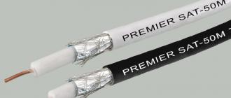
Unlike HF, the RG58 cable is not like VHF for powering antennas. RG213 or even lower loss cable should be used instead. When using 10 meters RG58 signal attenuation at 144 MHz is 1.82 dB, and at 450 MHz - 3.65 dB. For RG213, it is 0.86 dB and 1.73 dB, respectively. However, if the cable is short, only a couple of meters, then the RG58 will do.
We go on the air
Calling frequency in the range of 2 meters - 145.500 MHz. Just go in and make a general call, like on HF. They don't always answer. But if it is so without much fanaticism to call in the morning before work and in the evening after, then people regularly answer. Provided, of course, that you are using a normal transceiver, an effective antenna, and the correct cables, as described above.
At 70 cm, everything is a little more interesting. The official common calling frequency is 433.500 MHz. However, this frequency falls into the LPD range of 433.05-434.79 MHz and in Moscow there is a strong interference on it. The alternative frequency is 432.500 MHz. But this frequency falls within the range of 430-433 MHz, which is prohibited from using within a radius of 350 km from the center of Moscow. As far as I could find out, there is an agreement among Moscow radio amateurs to use 436.500 MHz as the calling frequency. You can also try the so-called "pharmacy" frequency, 436.600 MHz.
Fun fact! Like on HF, on VHF there are radio hooligans, many of whom behave incorrectly on the air, shall we say. My philosophy in life is that if you meet such a person on the air, don't talk to him about anything and make sure that you are standing as far as possible in frequency :)
Experiments show that in urban conditions the 2-meter range works much better than the 70 cm range. Although radio communications can be carried out both there and there. I also do not exclude that the matter is in my antenna, which is not particularly designed to work at 70 cm.
We work through repeaters
Often radio communications on VHF are conducted through repeaters. A repeater is a device that picks up your signal on one frequency and repeats it on another. Usually, the repeater antenna is installed somewhere high, where it can receive a signal from many radio amateurs, and the transmission from the repeater is carried out at high power. This is one of the reasons why it was said above that 5 watts is quite enough for working on VHF. The task comes down to getting through to the repeater. And it will already provide you with good power and coverage.
Repeaters often “open up” with a specific tone. A tone is a low frequency signal that is mixed with your voice during transmission. The main tone transmission standards are CTCSS and DCS.
The tone is not a repeater password. It is more of a foolproof protection. Let's say a radio amateur is equidistant between two repeaters using the same frequencies. With the help of a tone, one of the repeaters can understand that the radio amateur is talking to him and receive the signal. A second repeater using a different tone will recognize that the message is not addressed to him and will ignore the signal. Without the tone, the radio amateur would work simultaneously on two repeaters, and, unwillingly, would interfere with the work of colleagues.
The easiest way to find out about active local repeaters is to ask local radio amateurs about them. You can also search through the catalogs of repeaters, at least on the same qrz.ru. But information in catalogs is often either outdated or simply incorrect.
It is clear that to work through a repeater, the walkie-talkie must be properly configured. Let's consider this setting with a specific example. A familiar radio amateur says that in your city there is a repeater with an input at a frequency of 145.050 MHz and a transmission at 145.650 MHz (channel R2), a tone of 88.5 Hz. You are using a Kenwood TH-D72A radio. The question is, how to get to the repeater?
Press VFO and set the frequency to 145.650 MHz. Go to MENU → Radio → Repeater → Offset Freq, enter 0.6 MHz here, that is, the difference between the frequency of transmission and reception of the repeater. We press the green button F, and then SHIFT (located on the asterisk symbol, to the left of zero). The plus sign lights up on the screen. It means that when transmitting, the previously specified offset frequency will be added to the current frequency. But we want the frequency to be subtracted. Press F again, then SHIFT. The plus sign has changed to a minus sign. You can check that everything is working as expected by quickly pressing and releasing PTT. During transmission, the frequency should automatically change to 145.050.
Adjusting the tone. To do this, press TONE (located at number 8). The letter T lights up. It means that the radio will transmit a CTCSS tone, but will not require it to open the squelch. If you want the radio to check the tone during reception, you can change it from T to CT by pressing TONE again. In the same way, you can switch to using DCS instead of CTCSS. Then press the F button. Go to the Tone Freq selection. Specify 88.5 Hz, save.
Now, in order not to lose the settings, press F, and then M.IN. We save to a memory cell. You can now switch from VFO mode to MR mode and switch between stored channels. This is much more convenient than manually adjusting frequencies and tones all the time. If desired, the cell can be given a name in MENU → Memory → Name (only works in MR mode). Long press MR to enter continuous scan mode for stored channels.
If everything was done correctly, you should now be heard by the people on the repeater. You can check the connection to the repeater by short pressing PTT. After you release PTT, the repeater will transmit the carrier for some time, which you will hear. If there is no carrier, then either the repeater is not receiving your signal, or the tone has been incorrectly tuned, or the repeater is not working. If there is a carrier, then everything is fine.
Fun fact! With a certain amount of luck, it is possible to reach the repeater with 5 watts of the antenna located inside the house.
It is clear that when using a different radio, the setting will be different. But the principle will be the same, and I think that you can easily figure it out.
Conclusion
So, you are on VHF. Now what? You can stop there and just communicate for life with radio amateurs living nearby. Or you can learn how to use APRS, conduct radio communications via satellites or EchoLink, receive SSTV from the ISS, install your own repeater, experiment with antennas, filters, amplifiers, digital voice modes (D-STAR, C4FM, DMR), transceivers from different manufacturers, or maybe and homemade. You might even want to try EME, which is radio communications by bouncing radio waves off the moon. In general, you have a range of frequencies. What you will do on it is mainly limited by your imagination.
73 and see you on VHF!
Addition: Replacing the standard antenna Kenwood TH-D72A is discussed in the post
Details Views: 78775Russian radio amateurs, regardless of the category of their radio station, along with the HF bands, are allowed to work in the ultra-shortwave (VHF) bands.
The power of transmitters of category 4 radio stations when operating in the VHF bands should not exceed 5 watts, for radio stations of the 3rd and 2nd categories - 10 watts, for radio stations of the 1st category - 50 watts in the range of 144-146 MHz and 10 watts in VHF bands above 433 MHz. The power of transmitters of amateur radio stations operating in the 430-433 MHz frequency band should not exceed 5 watts. At the same time, the work of amateur radio stations in the 430-433 MHz frequency band in an area with a radius of 350 km. from the center of Moscow is prohibited.
For experimental radio communications using the Moon as a passive repeater (EME), as well as using the reflection of radio signals from meteor trails (MS), Russian radio amateurs with qualification category 1 are allowed to use a transmitter power of up to 500 watts.
Frequency plan of VHF bands for amateur radio stations in Russia
| Frequency bands, MHz | Types of radiation | ||||
| 1 cat | 2,3 cat | 4 cat | |||
| 144 MHz band (2 m) | |||||
| 144,035-144,110 | 0,5 | CW (Calling Frequency 144.050 MHz) | 50 | 10 | 5 |
| 144,110-144,150 | 0,5 | CW, DIGIMODE (narrowband modes; for PSK31 call frequency 144.138 MHz) | 50 | 10 | 5 |
| 144,165-144,180 | 3,0 | DIGIMODE (all types), CW | 50 | 10 | 5 |
| 144,180-144,360 | 3,0 | SSB (calling frequencies: 144,200 MHz and 144,300 MHz), CW | 50 | 10 | 5 |
| 144,360-144,400 | 3,0 | DIGIMODE (all types), CW, SSB | 50 | 10 | 5 |
| 144,400-144,490 | 0,5 | Beacons only (CW and DIGIMODE) | 50 | 10 | 5 |
| 144,500-144,794 | 25,0 | DIGIMODE (all types; call frequencies: SSTV - 144.500 MHz, RTTY - 144.600 MHz, FAX - 144.700 MHz, ATV - 144.525 and 144.750 MHz), (duplex: 144.630-144.660 MHz transmit, 144.660-144.690 MHz receive), ADS | 50 | 10 | 5 |
| 144,794-144,990 | 12,0 | DIGIMODE (APRS - 144.800 MHz) | 50 | 10 | 5 |
| 144,990-145,194 | 12,0 | FM, repeater only, receive, 12.5 kHz step | 50 | 10 | 5 |
| 145,194-145,206 | 12,0 | FM, space communication | 50 | 10 | 5 |
| 145,206-145,594 | 12,0 | FM (calling frequency 145.500 MHz); repeaters of previously recorded messages, step 12.5 kHz | 50 | 10 | 5 |
| 145,594-145,7935 | 12,0 | FM, repeater only, transmit, 12.5 kHz step | 50 | 10 | 5 |
| 145,7935-145,806 | 12,0 | FM (satellite only) | 50 | 10 | 5 |
| 145,806-146,000 | 12,0 | All views (only for work via satellites | 50 | 10 | 5 |
| 430 MHz band (70 cm) | |||||
| 430,000-432,000 | 20,0 | All kinds | 5 | 5 | 5 |
| 432,025-432,100 | 0,5 | CW (ringing frequency 432.050 MHz), DIGIMODE (narrowband modes, ringing frequency 432.088 MHz) | 5 | 5 | 5 |
| 432,100-432,400 | 2,7 | CW, SSB (calling frequency 432.200 MHz), DIGIMODE | 5 | 5 | 5 |
| 432,400-432,500 | 0,5 | Beacons only (CW and DIGIMODE) | 5 | 5 | 5 |
| 432,500-433,000 | 12,0 | All types (calling frequencies: APRS -432.500 MHz, RTTY - 432.500 MHz, FAX -432.700 MHz) | 5 | 5 | 5 |
| 433,000-433,400 | 12,0 | 10 | 10 | 5 | |
| 433,400-433,600 | 12,0 | FM (calling frequency 433.500 MHz); SSTV (calling frequency 433.400 MHz) | 10 | 10 | 5 |
| 433,600-434,000 | 25,0 | All types (calling frequencies: RTTY -433.600 MHz, FAX - 433.700 MHz, 433.800 MHz only for APRS), ADS | 10 | 10 | 5 |
| 434,025-434,100 | 0,5 | 10 | 10 | 5 | |
| 434,100-434,600 | 12,0 | All kinds | 10 | 10 | 5 |
| 434,600-435,000 | 12,0 | FM, repeater only, transmit, 25 kHz step | 10 | 10 | 5 |
| 435,000-440,000 | 20,0 | All modes, via satellites only 435-438 MHz | 10 | 10 | 5 |
| 1296 MHz band (23 cm) | |||||
| 1260,000-1270,000 | 20,0 | All types, work via satellite (Earth-to-space) | 10 | 10 | 5 |
| 1270,000-1290,994 | 20,0 | All kinds | 10 | 10 | 5 |
| 1290,994-1291,481 | 12,0 | FM, repeater only, receive, 25 kHz step | 10 | 10 | 5 |
| 1291,481-1296,000 | 150,0 | All kinds | 10 | 10 | 5 |
| 1296,025-1296,150 | 0,5 | CW, DIGIMODE (narrowband modes) | 10 | 10 | 5 |
| 1296,150-1296,800 | 2,7 | All modes (CW - 1296.200 MHz, FKS441-1296.370 MHz, SSTV - 1296.500 MHz, RTTY -1296.600 MHz, FAX - 1296.700 MHz) | 10 | 10 | 5 |
| 1296,800-1296,994 | 0,5 | Beacons only (CW and DIGIMODE) | 10 | 10 | 5 |
| 1296,994-1297,490 | 12,0 | FM, repeater only, transmit, 25 kHz step | 10 | 10 | 5 |
| 1297,490-1298,000 | 12,0 | FM, 25 kHz step, ringing frequency 1297.500 MHz | 10 | 10 | 5 |
| 1298,000-1300,000 | 150,0 | All kinds | 10 | 10 | 5 |
| 2400 - 2450 MHz range | |||||
| 2400-2427 | 150 | 10 | 10 | 5 | |
| 2427-2443 | 10000 | All types (work via satellite), ATV | 10 | 10 | 5 |
| 2443-2450 | 150 | All types (work via satellite) | 10 | 10 | 5 |
| Range 5650 - 5850 MHz | |||||
| 5650-5670 | 0,5 | CW, DIGIMODE (narrowband modes, Earth-to-space), ringing frequency 5668.2 MHz | 10 | 10 | 5 |
| 5725-5760 | 150 | DIGIMODE (all kinds) | 10 | 10 | 5 |
| 5762-5790 | 150 | DIGIMODE (all kinds) | 10 | 10 | 5 |
| 5790-5850 | 0,5 | CW, DIGIMODE (all types; satellite communications, space-to-Earth) | 10 | 10 | 5 |
| Range 10000 - 10500 MHz | |||||
| 10000-10150 | 150 | DIGIMODE (all types), CW | 10 | 10 | 5 |
| 10150-10250 | 10000 | All kinds | 10 | 10 | 5 |
| 10250-10350 | 150 | DIGIMODE (all types), CW | 10 | 10 | 5 |
| 10350-10368 | 150 | All kinds | 10 | 10 | 5 |
| 10368-10370 | 0,5 | CW, DIGIMODE (narrowband modes), ringing frequency 10368.2 MHz | 10 | 10 | 5 |
| 10370-10450 | 10000 | All kinds | 10 | 10 | 5 |
| 10450-10500 | 20 | All types (satellite communication) | 10 | 10 | 5 |
| Range 24000 - 24250 MHz | |||||
| 24000-24048 | 6000 | All types (satellite communication) | 10 | 10 | 5 |
| 24048-24050 | 0,5 | DIGIMODE (narrowband modes, satellite) | 10 | 10 | 5 |
| 24050-24250 | 10000 | All types (calling frequency 24125 MHz) | 10 | 10 | 5 |
| Range 47000 - 47200 MHz | |||||
| 47002-47088 | 6000 | All kinds | 10 | 10 | 5 |
| 47090-47200 | 10000 | All kinds | 10 | 10 | 5 |
| Range 76000 - 78000 MHz | |||||
| 76000-77500 | 10000 | All kinds | 10 | 10 | 5 |
| 77501-78000 | 10000 | All kinds | 10 | 10 | 5 |
| Range 122250 - 123000 MHz | |||||
| 122251-123000 | 10000 | All kinds | 10 | 10 | 5 |
| Range 134000 - 141000 MHz | |||||
| 134001-136000 | 10000 | All kinds | 10 | 10 | 5 |
| 136000-141000 | 10000 | All kinds | 10 | 10 | 5 |
| Range 241000 - 250000 MHz | |||||
| 241000-248000 | 10000 | All kinds | 10 | 10 | 5 |
| 248001-250000 | 10000 | All kinds | 10 | 10 | 5 |
2. Transmissions from amateur stations using repeaters on the VHF bands take precedence over other transmissions from amateur stations. Amateur radio operators must not interfere with these broadcasts.
3. To use repeaters of previously recorded messages, it is not required to obtain permission to use radio frequencies or radio frequency channels. The frequency of reception and transmission must be the same. At the same time, it is recommended to limit such use of RES. The operation of repeaters of previously recorded messages at frequencies of 145.45 and 145.5 MHz is prohibited.
Allocation of frequency bands for experimental radio communications using the Moon as a passive repeater (EME) for amateur radio stations in Russia
| Frequency bands, MHz | Max. signal bandwidth at the level of -6 dB, kHz | Types of radiation and uses (in order of priority) | Power depending on the category, W | ||
| 1 cat | 2,3 cat | 4 cat | |||
| 144 MHz band (2 m) | |||||
| 144,035-144,110 | 0,5 | CW (communications without prior arrangement - 144.100 MHz) | 500 | 10 | 5 |
| 144,110-144,150 | 0,5 | DIGIMODE (narrowband modes; for JT65: 144.120-144.150 MHz), CW | 500 | 10 | 5 |
| 144,150-144,165 | 3,0 | SSB, CW | 500 | 10 | 5 |
| 430 MHz band (70 cm) | |||||
| 432,000-432,025 | 0,5 | CW | 500 | 5 | 5 |
| 432,025-432,100 | 0,5 | CW, DIGIMODE (narrowband modes) | 500 | 5 | 5 |
| 432,100-432,400 | 2,7 | CW, SSB, DIGIMODE | 500 | 5 | 5 |
| 434,000-434,025 | 0,5 | CW, DIGIMODE (narrowband modes) | 500 | 10 | 5 |
| 1296 MHz band (23 cm) | |||||
| 1296,000-1296,150 | 0,5 | CW, DIGIMODE (narrowband modes) | 500 | 10 | 5 |
| Other VHF bands | |||||
| 2320,000-2320,150 | 0,5 | CW, DIGIMODE (narrowband modes) | 500 | 10 | 5 |
| 5760 - 5762 | 0,5 | CW, DIGIMODE (narrowband modes) | 500 | 10 | 5 |
| 10368 - 10370 | 0,5 | CW, DIGIMODE (narrowband modes) | 500 | 10 | 5 |
| 24048 - 24050 | 0,5 | CW, DIGIMODE (narrowband modes) | 500 | 10 | 5 |
| 47000 - 47002 | 0,5 | CW, DIGIMODE (narrowband modes) | 500 | 10 | 5 |
| 47088 - 47090 | 0,5 | CW, DIGIMODE (narrowband modes) | 500 | 10 | 5 |
| 77500 - 77501 | 0,5 | CW, DIGIMODE (narrowband modes) | 500 | 10 | 5 |
| 122250 - 122251 | 0,5 | CW, DIGIMODE (narrowband modes) | 500 | 10 | 5 |
| 134000 - 134001 | 0,5 | CW, DIGIMODE (narrowband modes) | 500 | 10 | 5 |
| 248000 - 248001 | 0,5 | CW, DIGIMODE (narrowband modes) | 500 | 10 | 5 |
Allocation of frequency bands for experimental radio communications using the reflection of radio signals from meteor tracks (MS) for amateur radio stations in Russia
A short time ago, mostly home-made equipment was used to work on the 144-145 MHz range. VHF transverters were popular among radio amateurs, many of which were comparable in size to the transceiver used with it. Radio amateurs converted decommissioned industrial VHF-type "Palma" radio stations to the amateur VHF range of 145 MHz, receiving a radio station operating on several channels. Then "Viola" became available to radio amateurs, and later "Mayaki" operating on forty channels. These radio stations then looked fantastic in their capabilities!
Currently, it is relatively inexpensive to purchase multichannel portable VHF transceivers of world famous companies - "YAESU", "KENWOOD", "ALINCO", which, in terms of their parameters and ease of operation, significantly surpass both homemade equipment in the 145 MHz range, and converted industrial equipment - "Palms "," Lighthouses "," Violas ".
But to work through a repeater from home, office, while driving when working from a car, an antenna is needed that is more effective than the "rubber band" used in conjunction with a portable radio station. When using a stationary "branded" VHF station, it is often advisable to use a homemade VHF antenna with it, since a decent "branded" outdoor antenna of the 145 MHz range is not cheap.
This material is devoted to the manufacture of simple homemade antennas suitable for use with stationary and portable VHF radio stations.
Features of 145 MHz antennas
Due to the fact that for the manufacture of antennas in the 145 MHz range, a thick wire is usually used - with a diameter of 1 to 10 mm (sometimes thicker vibrators are used, especially in commercial antennas), antennas in the 145 MHz range are broadband. This often makes it possible, when making the antenna exactly according to the indicated dimensions, to do without its additional tuning to the 145 MHz range.
To tune antennas in the 145 MHz range, you must have a SWR meter. It can be either a homemade device or an industrial one. On the 145 MHz range, radio amateurs practically do not use bridge antenna resistance meters, due to the apparent complexity of their correct manufacture. Although with careful manufacture of the bridge meter and, therefore, its correct operation in this range, it is possible to accurately determine the input impedance of the VHF antennas. But even using only the SWR - a through-type meter, it is quite possible to tune homemade VHF antennas. The power of 0.5 W, which is provided by imported portable radio stations in the "LOW" mode and domestic portable VHF radio stations such as "Dnepr", "Viola", "VEBR", is quite enough for the operation of many types of SWR meters. The "LOW" mode allows tuning antennas without fear of failure of the output stage of the radio station at any input impedance of the antenna.
Before starting tuning the VHF antenna, it is advisable to make sure that the SWR meter readings are correct. It is a good idea to have two VSWR meters rated for 50 and 75 ohm transmission paths. When tuning VHF antennas, it is advisable to have a control antenna, which can be either a "rubber band" from a portable radio station or a homemade quarter-wave pin. When tuning the antenna, the level of the field strength created by the tuned antenna is measured relative to the reference one. This makes it possible to judge the comparative efficiency of the tunable antenna. Of course, if a standard calibrated field strength meter is used in the measurements, an accurate estimate of the antenna performance can be obtained. When using a calibrated field meter, it is easy to remove the antenna directional pattern. But even using home-made field strength meters during measurements and having obtained only a qualitative picture of the distribution of the electromagnetic field strength, it is possible to draw a conclusion about the efficiency of the tuned antenna and approximately estimate its directional pattern. Consider the practical designs of VHF antennas.
Simple antennas
The simplest outdoor VHF antenna (Fig. 1) can be made using an antenna that works in conjunction with a portable radio station. On the window frame from the outside (Fig. 2) or from the inside, a metal corner is attached to an extension wooden bar, in the center of which there is a socket for connecting this antenna. It is necessary to strive to ensure that the coaxial cable leading to the antenna was the minimum required length. Along the edges of the corner are attached 4 counterweights, each 50 cm long. It is necessary to ensure good electrical contact of the counterweights, the antenna connector with the metal corner. The shortened twisted antenna of the radio station has an input impedance in the range of 30-40 ohms, so that a coaxial cable with a characteristic impedance of 50 ohms can be used to power it. With the help of the angle of inclination of the counterweights, it is possible to change the input impedance of the antenna within certain limits, and, therefore, to match the antenna with the coaxial cable. Instead of a proprietary "rubber band", you can temporarily use an antenna made of a copper wire with a diameter of 1-2 mm and a length of 48 cm, which is inserted into the antenna socket with its sharply sharpened end.
Figure 1. Simple outdoor VHF antenna

Figure 2. Construction of a simple outdoor VHF antenna
A VHF antenna made of a coaxial cable with the outer sheath removed is working reliably. The cable is terminated in an HF-connector similar to the connector of the "proprietary" antenna (Fig. 3). The length of the coaxial cable used for the manufacture of the antenna is 48 cm. Such an antenna can be used in conjunction with a portable radio station instead of a broken or lost standard antenna.
Figure 3. Simple homemade VHF antenna
For the quick manufacture of an external VHF antenna, you can use a connecting coaxial cable 2-3 meters long, which is terminated with connectors corresponding to the antenna jack of the radio station and antenna. The antenna can be connected to such a piece of cable using a high-frequency tee (Fig. 4). In this case, a “rubber band” antenna is connected from one end of the tee, and 50 cm counterweights are screwed on the other end of the tee, or another type of radio technical “ground” for the VHF antenna is connected through the connector.

Figure 4. Simple remote VHF antenna
Homemade portable radio antennas
If you lose or break the standard antenna of a portable radio station, you can make a homemade twisted VHF antenna. For this, a base is used - polyethylene insulation of a coaxial cable with a diameter of 7-12 mm and a length of 10-15 cm, on which initially 50 cm of a copper wire with a diameter of 1-1.5 mm is wound. It is very convenient to use a frequency response meter to tune a twisted antenna, but you can also use an ordinary SWR meter. Initially, the resonant frequency of the assembled antenna is determined, then, biting off part of the turns, shifting, moving apart the turns of the antenna, the twisted antenna is tuned to resonance at 145 MHz.
This procedure is not very complicated, and by tuning 2-3 twisted antennas, a radio amateur can tune new twisted antennas in literally 5-10 minutes, of course, if the above devices are available. After tuning the antenna, it is necessary to fix the turns either with electrical tape, or with a cambric soaked in acetone, or with a heat-shrinkable tube. After fixing the turns, it is necessary to check the frequency of the antenna again and, if necessary, adjust it using the upper turns.
It should be noted that in "branded" shortened twisted antennas, heat-shrinkable tubes are used to fix the antenna conductor.
Half-wave field antenna
For quarter-wave antennas to work effectively, multiple quarter-wave counterweights must be used. This complicates the design for a field quarter-wave antenna, which must be spaced out in relation to the VHF transceiver. In this case, you can use a VHF antenna with an electrical length of L / 2, which does not require counterweights for its operation, and provides a directional pattern pressed to the ground and ease of installation. For an antenna with an electrical length of L / 2, there is a problem of matching its high input impedance with the low characteristic impedance of the coaxial cable. An antenna with a length L / 2 and a diameter of 1 mm will have an input impedance on the 145 MHz band of about 1000 ohms. Matching using a quarter-wave resonator, which is optimal in this case, is not always convenient in practice, since it requires the selection of points for connecting the coaxial cable to the resonator for its effective operation and precise tuning of the antenna pin to resonance. The dimensions of the resonator for the 145 MHz range are also relatively large. The destabilizing factors on the antenna when it is matched using a resonator will be especially pronounced.
However, at low powers supplied to the antenna, quite satisfactory matching can be achieved using a P - loop, similarly to how it is described in the literature. A diagram of a half-wave antenna and its matching device is shown in Fig. 5. The length of the antenna rod is chosen slightly shorter or longer than the length L / 2. This is necessary so that even with a small difference in the electrical length of the antenna from L / 2, the active resistance of the antenna impedance decreases noticeably, and its reactive part at the initial stage increases insignificantly. As a result, matching with the help of the P - loop of such a shortened antenna is possible with greater efficiency than matching an antenna with a length of exactly L / 2. It is preferable to use an antenna slightly longer than L / 2.

Figure 5. Coordination of the VHF antenna using the P - loop
Air trimming capacitors of the KPVM-1 type were used in the matching device. Coil L1 contains 5 turns of 1 mm silver-plated wire wound on a mandrel with a diameter of 6 mm and a pitch of 2 mm.
Antenna tuning is not difficult. By including the SWR meter into the cable path of the antenna and at the same time measuring the level of the field strength created by the antenna, by changing the capacitance of variable capacitors C1 and C2, compressing-stretching the turns of the L1 coil, they achieve the minimum readings of the SWR meter and, accordingly, the maximum readings of the field strength meter. If these two maxima do not coincide, it is necessary to slightly change the length of the antenna, and repeat its adjustment again.
The matching device was placed in a case soldered from foil-clad fiberglass with dimensions of 50 * 30 * 20 mm. When working from a stationary workstation of a radio amateur, the antenna can be placed in the window opening. When working in the field, the antenna can be suspended from the upper end from a tree using a fishing line, as shown in fig. 6. A 50-ohm coaxial cable can be used to power the antenna. The use of a 75-ohm coaxial cable will slightly increase the efficiency of the antenna matching device, but at the same time, it will require tuning the output stage of the radio station to operate on a 75-ohm load.

Figure 6. Installing Antenna for Field Operation
Foil Window Antennas
Based on the adhesive foil used in security alarm systems, very simple designs of VHF window antennas can be built. This foil can be purchased with an adhesive base. Then, having freed one side of the foil from the protective layer, it is enough just to press it against the glass and the foil is instantly reliably glued. Foil without an adhesive base can be glued to glass using varnish or glue like "Moment". But for this you need to have some skill. The foil can even be secured to the window with adhesive tape.
With proper training, it is quite possible to make a good soldered connection between the center conductor and the braid of the coaxial cable with aluminum foil. Based on personal experience, each type of such foil requires its own flux for soldering. Some types of foil solder well even using rosin only, some can be soldered using soldering fat, other types of foil require the use of active fluxes. The flux must be tested on the specific type of foil used to make the antenna, well in advance of installation.
Good results are obtained by using a foil-clad fiberglass substrate for soldering and fixing the foil, as shown in Fig. 7. A piece of foil-clad fiberglass is glued to the glass using Moment glue, the antenna foil is soldered to the edges of the foil, the coaxial cable cores are soldered to the copper foil of the fiberglass at a short distance from the foil. After soldering, the connection must be protected with a moisture-resistant varnish or glue. Otherwise, this connection may corrode.

Figure 7. Connecting Antenna Foil to Coaxial Cable
Let us examine the practical designs of foil-based window antennas.
Vertical window dipole antenna
A diagram of a vertical dipole window VHF antenna based on a foil is shown in Fig. eight.

Figure 8. Windowed vertical dipole VHF antenna
The quarter-wave post and counterweight are positioned at 135 degrees to bring the antenna system's input impedance closer to 50 ohms. This makes it possible to use a coaxial cable with a wave impedance of 50 Ohm to power the antenna and use the antenna in conjunction with portable radio stations, the output stage of which has such an input impedance. The coaxial cable should run perpendicular to the antenna over the glass as long as possible.
Foil frame antenna
A frame window VHF antenna shown in Fig. 2 will work more efficiently than a dipole vertical antenna. 9. When the antenna is fed from the lateral angle, the maximum of the radiated polarization is in the vertical plane, when the antenna is fed in the lower angle, the maximum of the radiated polarization is in the horizontal plane. But at any position of the power points, the antenna emits a radio wave, with combined polarization, both with vertical and horizontal. This circumstance is very favorable for communication with portable and mobile radio stations, the position of the antennas of which will change during movement.

Figure 9. Frame VHF window antenna
The input impedance of the window loop antenna is 110 ohms. To match this impedance to a 50 Ohm coaxial cable, a quarter-wave section of 75 Ohm coaxial cable is used. The cable should run perpendicular to the antenna axis for as long as possible. The loop antenna has a gain of about 2 dB higher than a dipole window antenna.
When making foil window antennas with a width of 6-20 mm, they do not require tuning and operate in a frequency range much wider than the amateur band of 145 MHz. If the obtained resonant frequency of the antennas is lower than the required one, then the dipole can be tuned by symmetrically cutting off the foil from its ends. The loop antenna can be tuned using a jumper made from the same foil used to make the antenna. The foil closes the antenna web in the corner, opposite the power points. Once configured, contact between the jumper and the antenna can be made either by soldering or using adhesive tape. Such adhesive tape must press the jumper firmly against the antenna web in order to ensure reliable electrical contact with it.
Antennas made of foil can be supplied with significant power levels - up to 100 watts or more.
Outdoor vertical antenna
When placing the antenna outside the room, the question always arises about protecting the opening of the coaxial cable from atmospheric influences, about using a high-quality antenna support insulator, moisture-resistant wire for antennas, etc. These problems can be solved by installing a protected outdoor VHF antenna. The design of such an antenna is shown in Fig. 10.

Figure 10. Protected outdoor VHF antenna
A hole is made in the center of a 1 meter long plastic water pipe for the coaxial cable to fit tightly. Then the cable is threaded there, protrudes out of the pipe, is exposed at a distance of 48 cm, the cable shield is twisted and soldered at a length of 48 cm. The cable with the antenna is put back into the pipe. Standard plugs are put on the top and bottom of the pipe. It is not difficult to waterproof the hole where the coaxial cable enters. This can be done with automotive silicone or a fast curing automotive epoxy. As a result, we get a beautiful, moisture-insulated protected antenna that can work for many years under the influence of atmospheric influences.
To fix the vibrator and the antenna counterweight inside, you can use 1-2 cardboard or plastic washers tightly put on the antenna vibrators. The antenna tube can be installed on a window frame, on a non-metallic mast, or in any other convenient location.
Simple coaxial collinear antenna
A simple collinear coaxial VHF antenna can be made of coaxial cable. A piece of water pipe can be used to protect this antenna from the weather as described in the previous paragraph. The design of a collinear coaxial VHF antenna is shown in Fig. eleven.

Figure 11. Simple collinear VHF antenna
The antenna provides a theoretical gain of at least 3 dB more than a quarter-wave vertical. It does not need counterweights for its operation (although their presence improves the performance of the antenna) and provides a flattened radiation pattern to the horizon. A description of such an antenna has repeatedly appeared on the pages of domestic and foreign radio amateur literature, but the most successful description was presented in the literature.
Antenna dimensions in fig. 11 are in centimeters for coaxial cable with a shortening factor of 0.66. Most PE-insulated coaxial cables have this shortening factor. The dimensions of the matching loop are shown in Fig. 12. Without using this loop, the VSWR of the antenna system can exceed 1.7. If the antenna turned out to be tuned below the 145 MHz range, it is necessary to slightly shorten the upper section, if higher, then lengthen it. Of course, the optimal tuning is possible by proportional shortening-lengthening of all parts of the antenna, but this is difficult to do in an amateur radio environment.

Figure 12. Dimensions of the matching loop
Despite the large size of the plastic pipe required to protect this antenna from atmospheric influences, the use of a collinear antenna of this design is quite reasonable. The antenna can be moved away from the building using wooden battens, as shown in fig. 13. The antenna can withstand significant power input to it up to 100 watts or more and can be used in conjunction with both stationary and portable VHF radio stations. The use of such an antenna in conjunction with low-power portable radio stations will give the greatest effect.

Figure 13. Installing a collinear antenna
Simple collinear antenna
This antenna was assembled by me similarly to the construction of a car remote antenna used in a cellular radiotelephone. To convert it to the amateur band of 145 MHz, I proportionally changed all dimensions of the "telephone" antenna. As a result of this, an antenna was obtained, the diagram of which is shown in Fig. 14. The antenna provides a horizontal radiation pattern and a theoretical gain of at least 2 dB over a simple quarter-wave rod. A coaxial cable with a characteristic impedance of 50 Ohm was used to power the antenna.

Figure 14. Simple collinear antenna
A practical antenna design is shown in Fig. 15. The antenna was made from a single piece of copper wire with a diameter of 1mm. Coil L1 contained 1 meter of this wire, wound on a mandrel with a diameter of 18 mm, the distance between the turns was 3 mm. When performing a structure exactly to the dimensions, the antenna practically does not require adjustment. It may be necessary to slightly tune the antenna by squeezing-stretching the turns of the coil to achieve a minimum SWR. The antenna was housed in a plastic water pipe. Inside the pipe, the antenna wire was fixed with pieces of foam. Four quarter-wave counterweights were installed at the lower end of the pipe. They were threaded and fastened to a plastic pipe with nuts. Counterweights can be 2-4 mm in diameter depending on the ability to thread them. For their manufacture, you can use copper, brass, or bronze wire.

Figure 15. Construction of a simple collinear antenna
The antenna can be installed on wooden rails on the balcony (as shown in fig. 13). This antenna can withstand significant levels of power input.
This antenna can be thought of as a shortened HF antenna with a center extension coil. Indeed, the antenna resonance measured with a bridge resistance meter in the HF range turned out to be in the frequency region of 27.5 MHz. Obviously, by varying the diameter of the coil and its length, but keeping the length of its winding wire, it is possible to ensure that the antenna works both in the VHF range of 145 MHz and in one of the HF ranges - 12 or 10 meters. To operate on the HF bands, four L / 4 counterweights for the selected HF band must be connected to the antenna. This dual use of the antenna will make it even more versatile.
Experimental 5/8 wave antenna
When experimenting with radio stations of the 145 MHz range, it is often necessary to connect the antenna under test to its output stage in order to check the operation of the radio station's reception path or adjust the output stage of the transmitter. For these purposes, I have been using a simple 5/8 - wave VHF antenna for a long time, the description of which was given in the literature.
This antenna consists of a section of copper wire with a diameter of 3 mm, which is connected at one end to an extension coil and the other to a tuning section. At the end of the wire connected to the coil, a thread is cut, and at the other end, a tuning section made of copper wire with a diameter of 1 mm is soldered. The antenna is matched with a coaxial cable with a characteristic impedance of 50 or 75 Ohm by connecting to different turns of the coil, and may be a slight shortening of the tuning section. The antenna diagram is shown in Fig. 16. antenna design is shown in fig. 17.

Figure 16. Scheme of a simple 5/8 - wave VHF antenna

Figure 17. Construction of a simple 5/8 - wave VHF antenna
The coil is made on a plexiglass cylinder with a diameter of 19 mm and a length of 95 mm. At the ends of the cylinder, a thread is made into which the antenna vibrator is screwed on one side, and on the other side it is screwed to a piece of foil-clad fiberglass with dimensions of 20 * 30 cm, which serves as the “ground” of the antenna. On the back side, a magnet from an old speaker was glued to it, as a result of which the antenna can be attached to the windowsill, to the radiator, to other iron objects.
The coil contains 10.5 turns of 1 mm wire. The coil wire is evenly spaced over the frame. The coaxial cable is tapped from the fourth turn from the grounded end. The antenna vibrator is screwed into the coil, a contact lamella is inserted under it, to which the “hot” end of the extension coil is soldered. The lower end of the coil is soldered to the antenna ground foil. The antenna provides a SWR in the cable no worse than 1: 1.3. Tuning of the antenna is carried out by shortening its upper part with pliers, which is initially slightly longer than necessary.
I have experimented with installing this antenna on a window pane. In this case, an aluminum foil vibrator with an original length of 125 centimeters was glued to the center of the window. The extension reel was used the same and was installed on the window frame. The counterweights were made of foil. The ends of the antenna and counterweights have been curved slightly to fit on the window pane. Window 5/8 view - wave VHF antenna is shown in Fig. 18. The antenna is easily tuned into resonance by gradually shortening the vibrator foil using a blade, and by gradually switching the coil turns to minimize SWR. The window antenna does not spoil the interior of the room and can be used as a permanent antenna for operating on the 145 MHz band from home or office.

Figure 18. Window 5/8 - wave VHF antenna
Efficient Portable Radio Antenna
In the event that communication using a standard "rubber" is not possible, you can use a half-wave antenna. It does not require “ground” for its work and, when working over long distances, it gives a gain in comparison with a standard “rubber band” up to 10 dB. These are quite realistic numbers, given that the physical length of a half-wave antenna is almost 10 times longer than the "rubber band".
The half-wave antenna is supplied with voltage and has a high input impedance, which can reach 1000 ohms. Therefore, this antenna requires a matching device when used with a radio with a 50 ohm output. One of the variants of the P-loop matching device has already been described in this chapter. Therefore, for a change, for this antenna we will consider the use of another matching device, made on a parallel circuit. In terms of their efficiency, these matching devices are approximately equal. A diagram of a half-wave VHF antenna together with a matching device on a parallel circuit is shown in Fig. nineteen.

Figure 19. Half-wave VHF antenna with a matching device
The loop coil contains 5 turns of 0.8 mm diameter silver-plated copper wire wound on a 7 mm diameter mandrel along a length of 8 mm. Adjustment of the matching device consists in tuning the circuit L1C1 to resonance using a variable capacitor C1, and using a variable capacitor C2, the connection of the circuit with the transmitter output is regulated. Initially, the capacitor is connected in the third turn of the coil from its grounded end. Variable capacitors C1 and C2 must be air dielectric.
It is advisable to use a telescopic antenna for the antenna vibrator. This will make it possible to carry the half-wave antenna in a compact folded state. It also makes it easier to tune the antenna together with a real transceiver. During the initial tuning of the antenna, its length is 100 cm. During the tuning process, this length can be slightly adjusted for better antenna performance. It is advisable to make appropriate marks on the antenna in order to subsequently install the antenna from its folded position to the resonant length immediately. The box where the matching device is located must be made of plastic, in order to reduce the capacity of the coil to "ground", it can be made of foil-coated fiberglass. This depends on the actual operating conditions of the antenna.
The antenna is tuned using a field strength indicator. With the help of a SWR meter, antenna tuning is advisable only if it works not on the radio station body, but when using an extension coaxial cable together with it.
When the antenna is operating twice on the radio station housing and using an extension coaxial cable, two marks are made on the antenna pin, one corresponding to the maximum field strength level when the antenna is operating on the radio station housing, and the other risk corresponds to the minimum SWR when using an extension coaxial cable in conjunction with the antenna. Usually these two marks do not match slightly.
Gamma-matched vertical continuous antennas
Vertical antennas made of a whole vibrator are wind-resistant, easy to install, and take up little space. For their implementation, you can use copper tubes, aluminum power electrical wire with a diameter of 6-20 mm. These antennas can be easily matched with a coaxial cable with a characteristic impedance of both 50 and 75 ohms.
An inseparable half-wave VHF antenna, the design of which is shown in Fig. 20. Gamma matching is used to power it through the coaxial cable. The material from which the antenna vibrator is made and the gamma matching must be the same, for example, copper or aluminum. Due to mutual electrochemical corrosion of many pairs of materials, it is unacceptable to use different metals for antenna and gamma matching.

Figure 20. Continuous half-wave VHF antenna
If a bare copper tube is used to make the antenna, then it is advisable to adjust the antenna gamma matching using a closing jumper as shown in Fig. 21. In this case, the surface of the pin and the conductor of the gamma matching is carefully cleaned and using a clamp of bare wire as shown in fig. 21a achieve the minimum VSWR in the coaxial power cable of the antenna. Then, in this place, the gamma matching wire is slightly flattened, drilled and connected with a screw to the antenna web, as shown in Fig. 21b. Soldering is also possible.

Figure 21. Setting gamma - matching copper antenna
If an aluminum wire is used for the antenna from a power electrical cable in plastic insulation, then it is advisable to leave this insulation to prevent corrosion of the aluminum wire with acid rain, which is inevitable in urban environments. In this case, the antenna gamma matching is adjusted using a variable capacitor, as shown in Fig. 22. This variable capacitor must be carefully protected from moisture. If it is not possible to achieve the SWR in the cable less than 1.5, then the length of the gamma matching must be reduced and the setting repeated again.

Figure 22. Adjusting the gamma - matching of the aluminum-copper antenna
With sufficient space and materials, a continuous VHF vertical wave antenna can be installed. The wave antenna works more efficiently than the half-wave antenna shown in Fig. 20. A wave antenna provides a more horizontal radiation pattern than a half-wave antenna. You can match the wave antenna using the methods shown in Fig. 21 and 22. The design of the wave antenna is shown in fig. 23.

Figure 23. Continuous vertical wave VHF antenna
When performing these antennas, it is desirable that the coaxial power cable is at least 2 meters perpendicular to the antenna. The use of a balun together with a continuous antenna will increase the efficiency of its operation. When using a balun, use symmetrical gamma matching. The balun connection is shown in fig. 24.

Figure 24. Connecting the balun to a continuous antenna
Any other known balun can also be used as the antenna balun. When placing the antenna near conductive objects, it may be necessary to slightly reduce the length of the antenna due to the influence of these objects on it.
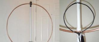
Round VHF antenna
If the placement in space of the vertical antennas shown in Fig. 20 and fig. 23 in their traditional vertical position is difficult, then you can place them by rolling the antenna web in a circle. The position of the half-wave antenna shown in Fig. 20 in the "round" version is shown in fig. 25, and the wave antenna shown in Fig. 23 in Fig. 26. In this position, the antenna provides combined vertical and horizontal polarization, which is favorable for communications with mobile and handheld radios. Although, theoretically, the level of vertical polarization will be higher with the side feeding of circular VHF antennas, in practice this difference is not very noticeable, and the side feeding of the antenna complicates its installation. The side power supply of the circular antenna is shown in Fig. 27.

Figure 25. Continuous round vertical half-wave VHF antenna

Figure 26. Continuous round vertical wave VHF antenna

Figure 27. Lateral power supply of circular VHF antennas
The round VHF antenna can be placed indoors, for example, between window frames, or outdoors, on a balcony or on a roof. When placing a circular antenna in the horizontal plane, we obtain a circular radiation pattern in the horizontal plane and the operation of an antenna with horizontal polarization. This may be necessary in some cases when conducting radio amateur communications.
Passive "amplifier" of the portable station
When testing or working with portable radios, sometimes there is not enough power for reliable communication. I made a passive "amplifier" for portable VHF stations. A passive "amplifier" can add up to 2-3 dB to the signal of a radio station on the air. This is often enough to reliably open the squelch of the correspondent station and ensure reliable operation. The design of the passive "amplifier" is shown in Fig. 28.

Figure 28. Passive "amplifier"
The passive "amplifier" is a large enough tinned coffee can (the bigger the better). A connector is inserted into the bottom of the can, which is similar to the antenna connector of a radio station, and a connector for connecting to the antenna jack is sealed into the lid of the can. 4 counterweights 48 cm long are soldered to the bank. When working with a radio station, this "amplifier" is switched on between the standard antenna and the radio station. Due to the more effective "ground" and there is an increase in the place of reception of the strength of the emitted signal. Other antennas can be used in conjunction with this "amplifier", for example, a L / 4 pin made of copper wire, simply inserted into the antenna socket.
Broadband survey antenna
Many imported portable radios provide reception not only in the amateur band of 145 MHz, but also in the survey ranges of 130-150 MHz or 140-160 MHz. In this case, for successful reception in survey ranges, on which a twisted antenna tuned to 145 MHz does not work effectively, you can use a broadband VHF antenna. The antenna diagram is shown in Fig. 29 and dimensions for different ranges of operation are given in table. one.

Figure 29. Broadband VHF vibrator
| Range, MHz | 130-150 | 140-160 |
| Size A, cm | 26 | 24 |
| Size B, cm | 54 | 47 |
Table 1. Dimensions of broadband VHF antenna
To work with the antenna, you can use a coaxial cable with a characteristic impedance of 50 Ohm. The antenna can be made of foil and glued to the window. You can make the antenna fabric from an aluminum sheet, or by printing on a piece of foil-clad fiberglass of suitable dimensions. This antenna can transmit and receive in the specified frequency ranges with high efficiency.
Zigzag antenna
Some service VHF long-distance radio stations use antenna arrays consisting of zigzag antennas. Radio amateurs can also try to use elements of such an antenna system for their work. The view of an elementary zigzag antenna included in the design of a complex VHF antenna is shown in Fig. thirty.

Figure 30. Elementary zigzag antenna
The zigzag elementary antenna consists of a half-wave dipole antenna that supplies voltage to the half-wave vibrators. In real antennas, up to five such half-wave vibrators are used. Such an antenna has a narrow directional pattern pressed to the horizon. The type of polarization emitted by the antenna is combined - vertical and horizontal. It is advisable to use a balun for antenna operation.
In antennas used in service communication stations, a reflector made of a metal mesh is usually placed behind elementary zigzag antennas. The reflector provides one-way directivity of the antenna. Depending on the number of vibrators included in the antenna and the number of zigzag antennas included together, the required antenna gain can be obtained.
Radio amateurs practically do not use such antennas, although they are easy to implement for the amateur VHF bands of 145 and 430 MHz. For the manufacture of the antenna sheet, you can use an aluminum wire with a diameter of 4-12 mm from a power electrical cable. In the domestic literature, a description of such an antenna, for which a rigid coaxial cable was used, was given in the literature.
Kharchenko antenna in the range of 145 MHz
Kharchenko's antenna is widely used in Russia for television reception and in service radio communications. But radio amateurs use it to work on the 145 MHz band. This antenna is one of the few that works very efficiently and requires little or no tuning. The diagram of Kharchenko's antenna is shown in Fig. 31.

Figure 31. Antenna Kharchenko
Both 50 and 75 ohm coaxial cables can be used for antenna operation. The antenna is broadband, operates in a frequency band of at least 10 MHz on a range of 145 MHz. To create a one-sided radiation pattern, use a metal mesh behind the antenna located at a distance of (0.17-0.22) L.
The Kharchenko antenna provides a width of the beam pattern in the vertical and horizontal planes close to 60 degrees. For further narrowing of the radiation pattern, passive elements in the form of vibrators with a length of 0.45L are used, located at a distance of 0.2L from the diagonal of the square of the frames. To create a narrow radiation pattern and increase the gain of the antenna system, several combined antennas are used.
Directional loop antennas in the range of 145 MHz
One of the most popular directional antennas for operation in the 145 MHz band are loop antennas. The most common two-element loop antennas on the 145 MHz band. In this case, an optimal cost / quality ratio is obtained. The diagram of a two-element loop antenna as well as the dimensions of the perimeter of the reflector and the active element are shown in Fig. 32.

Figure 32. VHF loop antenna
The antenna elements can be made not only in the form of a square, but also in the form of a circle, a delta. To increase the vertical component radiation, the antenna can be powered from the side. The input impedance of the dual element antenna is close to 60 ohms, and both 50 ohm and 75 ohm coaxial cables are suitable for operation. The gain of a two-element VHF loop antenna is at least 5 dB (above the dipole) and the ratio of radiation in the forward and reverse direction can reach 20 dB. It is useful to use a balun when working with this antenna.
Circularly polarized loop antenna
An interesting design for a circularly polarized loop antenna has been proposed in the literature. Circularly polarized antennas are used for communication via satellites. The dual feed of the 90-degree phase shift loop antenna allows the synthesis of a circularly polarized radio wave. The loop antenna power circuit is shown in Fig. 33. When designing an antenna, it is necessary to take into account that the length L can be any reasonable, and the length L / 4 must correspond to the wavelength in the cable.

Figure 33. Circularly polarized loop antenna
To increase the gain, this antenna can be used in conjunction with a loop reflector and a director. The frame must be powered only through a balun. The simplest balun is shown in Fig. 34.

Figure 34. The simplest balun
Industrial antennas of the range of 145 MHz
Currently on sale you can find a large selection of branded antennas for the 145 MHz band. If you have the money, of course, you can buy any of these antennas. It should be noted that it is advisable to purchase solid antennas already tuned to the 145 MHz range. The antenna must have a protective coating that protects it from corrosion by acid rain, which can fall in a modern city. Telescopic antennas are unreliable in urban environments and may fail over time.
When assembling antennas, it is necessary to strictly follow all instructions in the assembly instructions, and do not spare silicone grease for waterproofing connectors, telescopic joints and screw connections in matching devices.
Literature
- I. Grigorov (RK3ZK). Matching devices of the 144 MHz range // Radio amateur. KV and UKV-1997.-№ 12.-С.29.
- Barry Bootle. (W9YCW) Hairpin Match for the Collinear - Coaxial Arrau // QST.-1984.-October.-P.39.
- Doug DeMaw (W1FB) Build Your Own 5/8-Wave Antenna for 146 MHz // QST.-1979.-June.-P.15-16.
- S. Bunin. Antenna for communication through satellites // Radio. - 1985. - No. 12. - S. twenty.
- D. S. Robertson, VK5RN The “Quadraquad” - Circular Polarization the Easy Way //QST.-April.-1984.-pages16-18.
Ranges and frequencies of walkie-talkies
In this article, we will briefly consider which frequencies are allocated for radio communication and which radio stations and for which range should be considered when choosing equipment in a particular case. The article is presented in free form, using simplifications in some concepts and details. It does not pretend to be encyclopedic accuracy, but will give a general idea of the frequencies used in Russia and the radio communication equipment used.
Consider in what ranges do the radios work and why, in one case or another, different radio frequency ranges.
Shortwave range - 1-30 MHz
HF radio It is used mainly by the military, the Ministry of Emergency Situations, the navy, forestry and environmental organizations for professional communication over long distances - from 150 to 8000 km.
The main disadvantages of the HF range are low noise immunity and the need to use overall antennas up to several tens of meters long. Pros - absolute autonomy, long communication range and low cost compared to satellite communication.
Main equipment used: Icom, IC-M802., Vertex VX-1700, VX-1400, VX-1200/1210., Kenwood TK-90, Cordon R-12, Q-Mac HF 90M, Barrett PRC-2090, PRC- 2091, Karat, Angara.
Also, within 1-30 MHz, there are 9 frequency sections allocated for communication to radio amateurs. The main used HF amateur radio equipment is transceivers from Kenwood, Icom, Yaesu, Elecraft. If for professional stable radio communication, the range is usually limited to 8000 km, then radio amateurs often conduct transcontinental radio communications with their colleagues located on the other side of the world.
Currently, the market for software-based radio - SDR equipment is gaining momentum. Software-based radio is beginning to be widely used in amateur radio, military and commercial applications. To date, Harris and Alcatel Lucent have already implemented several successful projects that use equipment based on SDR technology and cognitive radio (a radio system capable of receiving information about the peculiarities of its own operation and, based on this data, adjust its operating parameters). In the future, SDR technology has every chance of becoming a new standard in the telecommunications market.
Civilian band - 27MHz
Conditionally referred to as the "27 MHz band". The frequency range is 25.6-30.1 MHz (the officially authorized section is 26.965-27.860 MHz). Another name is the CB range from the English abbreviation CB - Citizen Band.
Range of truckers on walkie-talkie this is the 15th channel, with a frequency of 27.135 MHz, in amplitude modulation (AM) mode. The channel is actively used by truckers for communication on the highways. In big cities B-band walkie-talkie 27 MHz, used by motorists to exchange traffic information. In different cities, different channels are used for urban communication. For example, in Krasnoyarsk this is channel 40, with a frequency of 27.405 MHz, in Kemerovo, the 27th channel, a frequency of 27.275 MHz. Frequency modulation (FM) is used on urban auto channel frequencies.
Also, the radio stations of this range are used by small taxi companies and freight carriers, rapid response groups of security companies and utilities. Despite the affordability of the equipment, and the fact that, according to the decree of the government of the Russian Federation of 13.10.2011 No. 837, walkie-talkie range 27 MHz are not subject to registration, it is necessary to take into account the fact that the civilian band is subject to large atmospheric and industrial interference and the use walkie-talkiesCB range for commercial purposes is not suitable for enterprises where high-quality radio communication is needed. Portable ci bi-band walkie-talkies, due to the small radius of action and relatively large dimensions, they have not received much distribution and are used mainly for loading and unloading operations or in parking lots of trucks.
Most of the CB radio stations available in Russia are presented in our online store.
Buy ci bi-band walkie-talkies which you can in our online store are presented in.
Low-Band range - 33-57.5 MHz
This is the lower section of the VHF mobile radio range.
Due to the large influence of industrial noise in cities and interference from TV broadcasting transmitters, this range is used mainly in rural areas. The main users, since the days of the USSR, are ambulance stations and agricultural enterprises. To date, most of the world's manufacturers have stopped producing radio stations for these frequencies. Equipment for the Low-Band range, at the moment, is offered by domestic manufacturers - the Granite and Vebr companies. In warehouses, you can still find radio stations from famous brands: Motorola GP340, GM360., Vertex Standard VX-3000L. Alinco, Inc. remains the only available foreign equipment manufacturer in the 33-57.5 MHz band. The company offers the DJ-V17L wearable radio and the DR-135LH and DR-M06R car (base) radios.
Air range - 118-137 MHz
Aircraft carry out radio communications with each other and with ground services in this frequency range. Unlike most other types of VHF communication, amplitude modulation is used. Popular equipment for the aviation band -
wearable aviation range walkie-talkie:
156.8375-174 MHz - mobile and fixed terrestrial communications.
In accordance with the basic law "On Communications" dated July 07, 2003 No. 126-FZ, for the organization of radio communications in this range, it is necessary to obtain a permit from the Federal State Unitary Enterprise "GRChTs". If you need to obtain frequencies, we can provide consulting and accompanying support in obtaining permits.
High noise immunity and good signal transmission made the 136-174 MHz range the most popular among users and equipment manufacturers. Most of the popular models of VHF radio stations and antennas are presented in our store. Walkie-talkiesVHF band in our store are presented in.
River range - 300 MHz
Used for communication on inland waterways.
Working frequencies of walkie-talkies are in the range 300.0125-300.5125 MHz and 336.0125-336.5125 MHz.
River range radio comes with pre-installed channels dedicated to communication with ships and shore services, for one purpose or another.
Frequencies of channel walkie-talkies- their numbers and purpose are established by the "Instructions on the organization of ship radio communications in the basin (region)" approved by the River Fleet Service of the Ministry of Transport of the Russian Federation and agreed with the local authorities of the State Supervision over Radio Communications. So, the main channels are:
Channel 2 (300.05 MHz) - for ship-to-ship communications;
Channel 3 (300.1 MHz) - for communication with gateway managers;
Channel 4 (300.15 MHz) - for communication with other river fleet services;
Channel 5 (300.2 MHz) - for calling ships, agreeing on the order of divergence and overtaking when maneuvering and transmitting distress signals.
Channel 25 and 43 (336.2 MHz and 300.125 MHz) are common for communication between yachts.
All radio stations installed on ships, on inland waterways, must necessarily have the Permit of the River Register of Russia (RRR) and the Certificate of the Ministry of Communications, regardless of their affiliation and whether these radio stations are the main or additional equipment.
According to the frequency allocation approved by the International Telecommunication Union (ITU), all over the world for communication between ships (rivers and seas), frequencies in the 156-162 MHz range are used. The river range of 300 MHz is used only in Russia and the choice of equipment offered for this range is small. Popular river radio stations: Radioma-300, Vertex Standard VX-451 / VX-454,.
VHF range - 400-470 MHz
In foreign sources, the range is designated as UHF, the name of which is formed from the capital letters Ultra High Frequency.
The peculiarities of the propagation of UHF frequencies make it possible to recommend this range for use in dense urban areas, in the mountains. In forest conditions, radio stations at 400 MHz are inferior to radio stations in the 136-174 MHz range.
In the range, frequency bands are allocated for professional use, for radio amateurs and for unlicensed use by everyone.
Frequencies of walkie-talkies, the work of which, in accordance with the basic law "On Communications" dated July 07, 2003 No. 126-FZ, is possible only with permits:
420-430 MHz - mobile and fixed terrestrial communications;
430-440 MHz - radio amateur band;
440-470 MHz - mobile and fixed terrestrial communications.
If it is necessary to obtain nominal frequencies, we can provide consulting and accompanying support in obtaining permits.
Sections of the range, which, according to the Decree of the Government of the Russian Federation of December 31, 2004 No. 896, do not require permits - allowed radio range(unlicensed frequencies):
433.075-434.775 MHz - LPD ("Low Power Device") range. Standard frequency grid of 69 nominal values, with a step of 25 kHz;