I. GRIGOROV (RK32ZK), Belgorod-15, PO Box 68.
Even 10 ... 15 years ago, there was practically no problem with the use of matching devices (CS), respectively, there were almost no descriptions of such devices in amateur radio literature.
The point, probably, is that earlier in the USSR, almost everyone used home-made lamp equipment, the output stage of which could be matched with almost anything.
Transistor RAs produce much more harmonics than tube ones. And often a low-quality P-circuit at the output of a transistor RA cannot cope with their filtering. In addition, it must be taken into account that the number of TV channels has increased many times over compared to what it was a few years ago!
The purpose of the matching device
The control system provides the transformation of the output impedance of the transmitter into the impedance of the antenna. It is irrational to use a control system with a tube power amplifier having a P-loop with all three smoothly tunable elements, since the P-loop provides matching in a wide range of output impedances. Only in cases where the elements of the P-loop exclude adjustment, the use of SU is beneficial.
In any case, the SU noticeably reduces the level of harmonics, and its use as a filter is fully justified.
With good tuned resonant antennas and good PA, there is no need to use a matching device. But when the antenna alone operates on several bands, and the RA does not always give out what is needed, the use of the SU gives good results.
Principles of building a matching device
The classical SU has the form shown in Fig. 1. As you can see, it consists of a matching circuit (CS), which is made according to one of the well-known schemes (the CS itself is often called "matching device", "ATU"), an SWR meter, an RF bridge that shows the degree of antenna mismatch, an equivalent antenna R 1, and control loads R2, R3. Without all this "environment" SU is only a chain of coordination, nothing more.
Let's analyze the principle of operation of the device. In the S 1 "Bypass" position, the transmitter output is connected to S2, which makes it possible either to directly connect the antenna, or to turn on one of the load equivalents (R2 or R3) to the output and check the possibility of matching the transmitter with it. In the "Setting" position, the transmitter operates on a matched load. Also, through the resistance R4, the RF bridge is turned on. According to the balance of this bridge, the matching circuit is used to tune the antenna. Resistors R2 and R3 make it possible to check whether it is possible to tune the matching circuit to them. Having configured the CA, turn on the "Work" mode. In this mode, the matching circuit is adjusted a little more to the minimum of the SWR meter readings.
Below we consider the main CAs used in practice.
Matching circuit on a parallel circuit
One of the most efficient and simple CAs is shown in Figure 2. The transmitter is connected via coil L1 and capacitor C1. L1 is from a quarter to a sixth of the number of turns of L2 and is wound in its lower part. L1 must be separated from L2 by good insulation.

Figure 2
In this scheme, the transmitter is connected to the CS only by magnetic flux, and here the issue of lightning protection of the output stage is automatically resolved. Capacitor C1 for operation at 1.8 MHz. should have a maximum capacitance - 1500 pF, and for operation at 28 MHz - 500 pF. C2 and C1 should have the largest possible gap between the plates. The load resistance range is from 10 ohms to several kilo ohms. High efficiency operation is provided in two adjacent bands, such as 1.8 and 3.5 MHz. For efficient operation in several ranges, it is necessary to switch L1 and L2. At low powers (up to 100 W), it is most efficient and easy to make a set of replacement coils and install them using base panels from old radio tubes. Any experiments related to connecting L1 and L2 coils in parallel to reduce their inductance for operation on the HF bands, connecting these coils to the taps, the "cunning" parallel connection of the coils, significantly reduces the efficiency of this DC at HF. The coil data for the circuit in Fig. 2 are shown in Table 1.
Range, MHz | |||||||||
Coil diameter, mm | |||||||||
Winding length, mm | |||||||||
Number of turns |
Although symmetrical antennas are rarely used at present, it is worth considering the possibility of operating this DS on a symmetrical load (Fig. 3).

Figure 3
Its only difference from the circuit in Fig. 2 is that the voltage for the load is removed symmetrically. L1 must be located symmetrically with respect to L2. Capacitors C1 and C2 must be on the same axis. It is necessary to take measures to reduce the influence of the capacitive effect on L2, i.e., it should be located far enough from the metal walls. The L2 data for the circuit in Fig. 3 are given in Table 2.
Range, MHz | |||||||||
Coil diameter, mm | |||||||||
Winding length, mm | |||||||||
Number of turns |
There are also constructions of a simplified version of this CA.

Fig.4
Figure 4 shows an asymmetric circuit, Figure 5 shows a symmetrical circuit. But, unfortunately, as experience shows, these circuits cannot give such careful coordination as in the case of using capacitors C3 (Fig. 2) or C3.1, C3.2 (Fig. 3).

Fig.5
Particular care must be taken in the construction of multi-band DS operating on this principle (Fig. 6). Due to the decrease in the Q-factor of the coil and the large capacity of the ground taps, the efficiency of such a system in the HF bands is low, but the use of such a system in the 1.8 ... 7 MHz bands is quite acceptable.

Fig.6
Setting up the CA shown in Figure 2 is simple. Capacitor C1 is set to the maximum position, C2 and C3 - to the minimum, then with the help of C2 the circuit is tuned to resonance, and then, increasing the connection with the antenna using C3, they achieve maximum power output to the antenna, while constantly adjusting C2 and, according to opportunities, C1. You should strive to ensure that after setting up the DS, the SZ has the maximum capacity.
T-chain matching
This scheme (Fig. 7) is widely used when working with asymmetric antennas.

Fig.7
For the normal operation of this DC, a smooth adjustment of the inductance is necessary. Sometimes even half a turn is critical to matching. This limits the use of tapped inductors or requires individual selection of the number of turns for a particular antenna. It is necessary that the capacitance of C1 and C2 to the "ground" be no more than 25 pF, otherwise the efficiency may decrease by 24 ... 28 MHz. It is necessary that the "cold" end of the L1 coil be carefully grounded. This DC has good parameters: efficiency - up to 80% with the transformation of 75 ohms to 750 ohms, the ability to match the load from 10 ohms to several kilo-ohms. With only one variable inductance of 30 μH, you can cover the entire range from 3.5 to 30 MHz, and by connecting C1, C2 constant capacitors of 200 pF in parallel, you can also work at 1.8 MHz.
Unfortunately, variable inductance is expensive and structurally complex. W3TS proposed a switchable "digital inductor" (Figure 8). Using such an inductance, with the help of switches, you can visually set its desired value.
Another attempt to simplify the design was made by AEA by making a matching device according to the scheme shown in Fig. 9. Indeed, the circuits in Fig. 7 and Fig. 9 are equivalent. But structurally it is much easier to use one grounded high-quality capacitor instead of two isolated ones, and replace the expensive variable inductance with cheap permanent inductors with taps. This DS worked well from 1.8 to 30 MHz, transforming 75 ohms to 750 ohms and 15 ohms. But when working with real antennas, the discreteness of inductance switching sometimes affected. In the presence of 18, and preferably 22 position switches, this CA can be recommended for practical implementation. In this case, it is necessary to reduce the length of the coil leads to the switch to a minimum. Switches for 11 AEA AT-30 TUNER L1-L2-25 Turns, diam. coils 45 mm winding pitch 4 mm taps from each turn along the length of 10 turns then after 2 turns of positions make it possible to make a CS only for working on a part of the amateur bands - from 1.8 to 7 or from 10 to 28 MHz.

Figure 9
The coil is structurally convenient to perform as shown in Fig. 10. Its frame is a bar of double-sided fiberglass with cuts for coil turns. A switch is installed on this bar (for example, 11P1N). The taps from the coil go to the switch on both sides of the fiberglass strip.

Fig.10
When working with symmetrical antennas, together with a T-shaped matching device, a balancing transformer 1:4 or 1:6 is used at the output of the DS. Such a solution cannot be considered effective, since many symmetrical antennas have a large reactive component, and ferrite transformers work very poorly with a reactive load. In this case, it is necessary to apply measures to compensate for the reactive component or use a DS (Fig. 3).
U-shaped matching scheme
U-shaped CS (or P-loop), the scheme of which is given in fig. 11 is widely used in amateur radio practice.

Figure 11
In real conditions, when the transmitter output is 50 ... 75 Ohm, and matching must be done in a wide range of load resistances, the parameters of the P-loop change tenfold. For example, at 3.5 MHz with Rin \u003d Rn \u003d 75 Ohm, the inductance L1 is approximately 2 μH, and C1, C2 - 2000 pF each, and with Rin \u003d 75 Ohm and RH a few kiloohms, the inductance L1 is approximately 20 μH, the capacitance Cl is about 2000 pF, and C2 is tens of picofarads. Such large variations in the values of the elements used limit the use of the P-loop as a CS.
It is desirable to use a variable inductance. Capacitor Cl may have a small gap, and C2 should have a gap of at least 2 mm for every 200 watts of power.
Improving the efficiency of the matching device
To increase the efficiency of the transmitter, especially when using random antennas, a device called "artificial earth" helps. This device is effective when using random antennas and with poor radio grounding. This device brings to a resonant state the grounding system of the radio station (in the simplest case, a piece of wire). Since the parameters of the ground are included in the parameters of the antenna system, improving the efficiency of the ground improves the performance of the antenna.
Conclusion
The matching device should be used no more than it is really needed. You should choose the type of SU that you need. For example, it makes no sense to manufacture a broadband device for operation in the range of 1.8 ... 30 MHz, if you really do not "build" antennas for 1 ... 2 ranges, or surrogate antennas are used on these ranges. Here it is much more efficient to perform its own separate SU for each range. But of course, if you are using a transceiver with a non-adjustable output and most of your antennas are surrogate, then an all-band DC is needed here.
All of the above applies to the "artificial earth" device.

Fig.12
Literature
1. (EW1MM). HF ground/Ham radio. KB and VHFN9.
2. (RK3ZK). Matching device on a coaxial cable / Radio amateurN7.
3. (UC2AGL). Antenna tuner / Radio amateur. -1994.-N2.
4. (UC2AGL). Antenna tuner / Radio amateur. -1991.-N1.
5. (UZ3ZK). Universal matching device//RadioamateurN11.
6. (RA6LEW). Antenna switching and matching device / Radio amateur N 12.
7. (UT5JAM). All-band matching device for LW / Radio amateur. -1992. - N 10.
8. (F9HY). Coordinating device for LEVY/ /radioamateur N10 antennas.
9. (EW1MM). Universal Antenna Coordinator / Ham Radio N8.
Universal matching deviceThe device is designed to match the transmitter with various types of antennas, both with a coaxial feeder and with an open input (such as "long beam", etc.). The use of the device allows you to achieve optimal matching of the transmitter on all amateur bands, even when working with an antenna of random length. The built-in SWR meter can be used when tuning and adjusting antenna-feeder systems, as well as an indicator of the power delivered to the antenna. The matching device operates in the range of 3-30 MHz and is designed for power up to 50 watts. With a corresponding increase in the electrical strength of the parts, the permissible power level can be increased. Schematic diagram of the matching device is shown in fig. 1. It includes two functional units: the matching device itself (coils L1 and L2, capacitors C6-C9, switches B2 and B3) and an SWR meter assembled according to the balanced RF bridge circuit.
The device is mounted on a chassis. All the tuning controls are displayed on the front panel, and the dial indicator of the SWR meter is also installed on it. On the rear wall of the chassis, there are two high-frequency connectors for connecting the output of the transmitter and antennas with a coaxial feeder, as well as a bushing with a clamp for antennas of the "long beam" type, etc. The SWR meter is mounted on a printed circuit board (see Fig. 2) .
Capacitors C1 and C2 - air or ceramic with an initial capacity of 0.5-1.5 pF. The RF transformer Tr1 is wound on a ferrite ring M30VCh2 with dimensions 12X6X X4.5 mm. The secondary winding contains 41 turns of PELSHO 0.35 wire, the winding is evenly spaced around the ring. The primary winding consists of two turns of PEV-1 0.51 wire. The inductor Dr1 is wound on a ring of ferrite 600NN with dimensions 10X6X X4 mm and contains 150 turns of PELSHO 0.18 wire, evenly spaced around the ring. Coil L1 is wound on an M30VCh2 ring with dimensions of 32X15x8 mm and contains 23 turns of PEV-2 0.81 wire. Taps are made from 1, 2, 4, 6, 8, 10, 12, 14, 16 and 19 turns. The winding is insulated with two layers of PTFE tape. Coil L2 is wound on an M30VCh2 ring 12X X6X4.5 mm and contains 30 turns of PELSHO 0.41 wire. Blocks of variable capacitors - self-made, from air-tuned capacitors of the KPV type. The design of their articulation into blocks can be any, it is only important to ensure the isolation of the rotors and stators from the chassis. The matching device itself does not require any adjustment. The SWR meter is set up as follows. A wire is soldered from the printed circuit board to the capacitors C6, C7. A resistor with a resistance of 75 ohms and a power of 5-10 W is connected to it (several MLT-2 resistors can be used connected in parallel). The meter input is connected to the transmitter. Switch B1 is set to the "Direct" position. Such an RF voltage (with a frequency of 21 or 28 MHz) is applied so that the indicator needle deviates to the full scale. Then set the switch to the "Reflected" position and adjust the capacitor C2 to achieve zero readings of the indicator. If this fails, select a resistor R2 or a diode D2. Swap the load and the output of the transmitter and repeat the setting of the capacitor C1, as well as the selection of the resistor R1 and the diode D1. The ratios of the direct and reflected waves, corresponding to SWR == 1, in a properly tuned meter must be maintained over the entire frequency range. For a general check of the matching device, the transmitter is connected to the input of the device, and an active load with a resistance of 75-200 Ohms is connected to its output. Capacitors C6 and C7 are set to the maximum capacitance position, the switches are set to the positions shown in the diagram. The transmitter is turned on and resistor R3 achieves the deviation of the indicator arrow on the full scale. Move switch B1 to the "Reflected" position and switch B2 to achieve the minimum reading of the indicator. Then, by adjusting the variable capacitors C6 and C7, zero readings of the indicator are achieved, which corresponds to the SWR value = 1 and indicates full matching of the transmitter output with the equivalent load. On high frequency bands, it may be necessary to connect the L2 coil in parallel with L1. A similar setup procedure is performed when connecting real types of antennas. The SWR is calculated according to the formula KCB=(A+B)/(A-B) where A is the reading on the indicator scale for a direct wave. B-for reflected. The scale can be calibrated directly in SWR units. The described device is used by the author with an "oblique beam" antenna 80 m long. On all amateur bands, it is possible to obtain complete antenna matching with the transmitter. Television interference is completely absent. This device was tested on the UA4IF radio station when working with a piece of wire of random length (15-17 m). On all amateur bands, an agreement was obtained with an SWR of no worse than 1.2 - 1.5. Eng. V. KOBZEV (UW4HZ) Kuibyshev, RADIO 9/75 |


matching device.
The choice depends on the antennas used at the station. If the input impedances of the radiating systems do not fall below 50 ohms, you can get by with a primitive L-type matching device,
https://pandia.ru/text/77/515/images/image016_7.gif" width="398" height="261 src=">
Antenna tuners in the form of separate devices of the company are often manufactured according to the scheme
antennas "nobody will appreciate. As a control system, you can also use a regular P-loop,
In branded antenna tuners, coils with a “runner” are used in which the first turns are wound with an increased pitch - this is done to obtain small inductances with maximum quality factor and minimum turn-to-turn coupling. two coils connected in series with switching taps,
the variometer of a poor radio amateur "does it successfully. By the way, in the tuner of such an expensive TRX as the TS-940, only 7 taps are used, and the automatic antenna tuners AT-130 from ICOM use 12 taps, AT-50 from Kenwood - 7 taps - so don't think that the option described here is “a primitive that does not deserve your attention." In our case, we have an even "cooler" option - accordingly, a more accurate setting - 20 taps. The gaps between the plates in the KPI must withstand the expected voltage. If low-resistance loads are used, you can get by with KPI from old types of RPU, with an output power of up to 200-300 W. If high-resistance, you will have to pick up KPI from radio stations with the required clearances. The calculation is simple - 1mm can withstand 1000V, the estimated voltage can be found from the formula P \u003d U` (squared) / R , where P is the power, R is the load resistance, U is the voltage.There must be a switch on the radio station, with which the transceiver is disconnected from the antenna in case of g roses or out of order, because more than 50% of transistor failures are due to static electricity. It can be entered either in the antenna switching shield or in the SU.
Description of the matching device.
As a result of various experiences and experiments on this topic, the author was led to the scheme of a U-shaped "matcher".
Electroplating "href="/text/category/galmzvanika/" rel="bookmark"> is galvanically isolated from the transceiver input through the gaps between the KPI plates. But the unsuccessful search for suitable KPIs for this circuit forced us to abandon it. By the way, the P-loop circuit is used and some companies that produce automatic tuners - the same American KAT1 Elekraft or Dutch Z-11 Zelfboum.In addition to matching, the P-loop also acts as a low-pass filter, which is quite good for overloaded amateur radio bands, probably, hardly anyone will refuse additional filtering of unnecessary harmonics.The main drawback of the P-loop circuit is the need for a KPI with a sufficiently large maximum capacitance, which makes me think why such schemes are not used in automatic tuners of imported transceivers.T-shaped circuits most often use two KPIs tunable by motors and it is clear that a 300pf KPI will be much smaller, cheaper and simpler than a 1000pf KPI. KPI from lamp receivers with an air gap of 0.3 mm are used, both sections are connected in parallel. As an inductance, a coil with taps switched by a ceramic biscuit switch is used. A frameless coil of 35 turns of wire 0.9-1.1 mm is wound on a mandrel with a diameter of 21-22 mm, folded into a ring and soldered to the terminals of the biscuit switch with its short taps. The taps are made from 2,4,7,10,14,18,22, 26,31 turns. The SWR meter is made on a ferrite ring. For HF, the permeability of the ring is generally not of decisive importance - a K10 ring with a permeability of 1000 NN is used. It is wrapped with a thin varnished cloth and 14 turns are wound on it in two wires without twisting PEL 0.3, the beginning of one winding, connected to the end of the second, forms the middle output. Depending on the required task, more precisely, on what power is supposed to pass through this control system and the quality of the emitting LEDs, silicon or germanium detecting diodes D2, D3 can be used. From germanium diodes, you can get greater amplitudes and sensitivity. The best - GD507. But since the author uses a transceiver with an output power of at least 50W, ordinary silicon KD522 is enough. As a "know-how" in this control system, LED indication of the setting is used in addition to the usual one on the pointer device. The green LED AL1 is used to indicate the "forward wave", and the red LED AL2 is used to visually control the "reverse wave". As practice has shown, this solution is very successful - you can always quickly respond to an emergency - if something happens while working with a load, the red LED starts to flash brightly in time with the transmitter, which is not always so noticeable on the SWR meter. You won’t constantly stare at the SWR meter needle during the transmission, but the bright glow of red light is clearly visible even with peripheral vision. This was positively appreciated by RU6CK when he got such an SU (besides, Yuri has poor eyesight). For more than a year, the author himself has been using mainly only the “LED setting” of the SU - that is, the setting is reduced to ensuring that the red LED goes out and the green one blazes brightly. If you really want a more precise setting, you can “catch” it by the arrow of the microammeter. The device is configured using the load dummy for which the output stage of the transmitter is designed. We connect the SU to the TRX of the minimum (as far as possible - since this piece will later be used to connect them) with a coaxial cable with the required wave impedance, to the output of the SU without any long laces and coaxial cables equivalent, we unscrew all the SU handles to a minimum and use C1 to set the minimum readings of the SWR meter with “reflection”. It should be noted that the output signal for tuning should not contain harmonics (that is, it must be filtered), otherwise there will be no minimum. If the design is done correctly, the minimum is obtained in the area of \u200b\u200bthe minimum capacity C1. We swap the input-output of the device and again check the “balance”. We check the setting on several ranges - if everything is OK, then the setting to the minimum will coincide in various positions. If it doesn’t match or doesn’t “balance” - look for a better “oil” in the inventor’s head ... I only tearfully ask - do not ask the author questions on how to make or set up such a control system - you can order a ready-made one if you can’t do it yourself. All information can be found at http://hamradio. /ut2fw You can also view all the pictures there. Or by E-mail: *****@***net LEDs must be selected from modern ones with maximum brightness of the glow at maximum resistance. I managed to find red LEDs with a resistance of 1.2kOhm and green 2kOhm. Usually green ones glow weakly - but this is not bad - we do not make a Christmas tree garland. The main task is to make it glow quite clearly in the normal mode for the transmission of the transceiver. But red, depending on the goals and preferences of the user, you can choose from poisonous raspberry to scarlet. As a rule, these are LEDs with a diameter of 3-3.5 mm. For a brighter red glow, a doubling of the voltage is applied - a diode D1 is introduced. Because of this, our SWR meter can no longer be called an accurate measuring device - it overestimates the “reflection” and if you want to calculate the exact SWR value, you will have to take this into account. If there is a need to measure exact SWR values, you need to use LEDs with the same resistance and make the two arms of the SWR meter exactly the same - either with doubling the voltage, both or both without it. Only in this case will we obtain the same value of stresses coming from the arms Tr to MA. But rather, we are more concerned not with what kind of SWR we have, but with the fact that the TRX antenna circuit is consistent. For this, the indications of the LEDs are quite enough. This SU is effective when used with unbalanced antennas fed through a coaxial cable. The author carried out tests on "standard" common antennas of "lazy" radio amateurs - a frame with a perimeter of 80m, Inverted-V combined 80 and 40m, a triangle with a perimeter of 40m, a pyramid at 80m. Konstantin RN3ZF uses such a control system with a pin, Inverted-V, including on WARC bands, he has an FT-840. UR4GG is used with 80m triangle and Volna and Danube transceivers. UY5ID coordinates the silo on KT956 with a multi-sided frame with a perimeter of 80 m with symmetrical power, uses an additional "transition" to a symmetrical load. If during tuning it is not possible to turn off the red LED (to achieve the minimum readings of the device), this may indicate that, in addition to the main signal, there are more components in the emitted spectrum and the control system is not able to skip them and coordinate them simultaneously at all emitted frequencies. And those harmonics that lie above the main signal in frequency do not pass through the low-pass filter, formed by the SU elements, are reflected and the red LED is “lit on fire” on the way back. The fact that the control system does not “cope” with the load can only be indicated by the fact that the matching occurs at extreme values (not minimum) of the KPI and coil parameters - i.e. e. not enough capacitance or inductance. None of the users on the listed antennas on any of the ranges of such cases was noted. The use of a control system with a "rope" - a wire 41 m long was tested. It should not be forgotten that the SWR meter is a measuring instrument only if there is a load on both sides of it at which it is balanced. When tuned to the “rope”, both LEDs are lit, and as a reference point, you can take the brightest green glow with the lowest possible red. It can be assumed that this will be the most correct setting - for maximum return to the load. I would also like to note that in no case should the coil taps be switched when the maximum power is emitted. At the moment of switching, the circuit breaks (albeit for a fraction of a second) - the inductance changes sharply - accordingly, the contacts of the biscuit switch burn out and the load on the transceiver changes dramatically. Switching the hard switch must be done when the transceiver is set to RX. An M68501 device with a total deflection current of 200 μA was used as a microammeter. View of the device can be seen at http://hamradio. /ut2fw/port/photo/dop_mam. jpg M4762 can also be used - they were used in tape recorders "Nota", "Jupiter". It is clear that C1 must withstand the voltage output by the transceiver in the load. Information for meticulous and "demanding" readers - the author is aware that this type of SWR meter is not a precision high-precision measuring instrument. The manufacture of such a device was not set! The main task was to provide the transceiver with broadband transistor cascades with an optimal matched load, I repeat once again, both for the transmitter and the receiver. The receiver in the same full extent needs high-quality coordination with the antenna, as well as a powerful silo !!! By the way, if in your “radiv” the optimal settings for the receiver and transmitter do not match, this indicates that the setting was either not really done at all, and if it was done, then most likely only the transmitter and the receiver’s bandpass filters have optimal parameters for other load values than it was debugged on the transmitter. The task of our SWR meter is to show that by twisting the SU knobs we have achieved the parameters of the load that was connected to the ANTENNA output during tuning. And we can safely work on the air, knowing that now the transceiver is not “puffing up and begging for mercy”, but has almost the same load to which it was tuned. This, of course, does not mean that your antenna began to work better from this SU, do not forget about it! For those who suffer from a precision SWR meter, I can recommend making it according to the schemes given in many serious foreign publications or buying a ready-made device. But you have to fork out - indeed, devices from well-known companies cost from $ 50 and more, I do not take into account the SV-ish Polish-Turkish-Italian ones. A good and complete article on the manufacture of an SWR meter was in the Radio magazine No. 6 1978, author M. Levit (UA3DB), its electronic version was prepared and posted on the site: http://hamradio. /ut2fw/port/dop_atu. htm
matching devices.
The standing wave ratio (SWR) is one of the main characteristics of the antenna-feeder path of an amateur radio station. The device described in this article allows you to measure the power incident and reflected from the load (and, therefore, determine the SWR) in a coaxial path with a wave impedance of 75 or 50 ohms at frequencies up to 30 MHz.
The schematic diagram of the device is shown in fig. one.
|
|


It consists of two high-frequency diode voltmeters V1 and V2, which measure the reflected and incident power. The high-frequency voltage is supplied to the cathodes of the diodes from the capacitive dividers C1C2 and C8C9. It is proportional to the voltage in the transmission line. The electrical length of the measuring line (from connector X1 to connector X2) is chosen to be significantly less than the wavelength, so the high-frequency voltage applied to diode V1 is in phase with the high-frequency voltage across diode V2. An RF voltage proportional to the current in the transmission line is supplied to the anodes of the diodes through the transformer T1. It is supplied to diode V1 from resistor R4, and to diode V2 - from resistor R5. The voltages supplied to the diodes from these resistors are antiphase. In the case of a matched load, the voltage and current in the transmission line are in phase. In this case, the RF voltages supplied to the cathode and anode of one diode (which one - V1 or V2 - depends on how the beginning and end of the secondary winding of the transformer T1 are turned on) will be in phase, and to the cathode and anode of the second diode - out of phase. Let, for definiteness, common-mode voltages be applied to diode VI. (Plots of RF voltages at various points of the device for this case are shown in Fig. 2, a. Here Uu is the voltage at the cathodes of diodes V1 and V2, Ui, is the voltage at the anode of diode V1, Ui2 is the voltage at the anode of diode V2, Uv1 is the resulting The RF voltage between the cathode and the anode of the diode V1. Uv2 is the same for the diode V2.) Then by selecting the RF voltage at the cathode of the diode using the tuning capacitor C1, you can achieve equality of these voltages in amplitude. There will be no rectified current in the circuit of this diode, and, therefore, the RF voltmeter on diode V1 registers the reflected power. In this case, the rectified current in the circuit of the diode V2 will have a maximum value. We note right away that the device is symmetrical and will work if a transmitter is connected to the X2 connector, and an antenna to the X1 connector. However, the RF voltmeters on diodes V1 and V2 will switch roles: the first will now measure the incident power, and the second - the reflected. This property of the device is used in its adjustment. With an unmatched load, the amplitudes of the RF voltage and current in the transmission line change, and a phase shift appears between them. As a result, the resulting voltage on the diode V1 will no longer be equal to zero, and the RF voltage on the diode V2 will also change (Fig. 2, b). A few words about the purpose of the remaining elements. Capacitors C5 and C6 correct the frequency response of transformer T1, ensuring a constant transmission coefficient over the entire operating frequency range. Trimmer resistors R2 and R6 set the sensitivity of the device. Measuring device PA] is connected to the RF voltmeters by switch S1.
The device is best done in the form of two blocks: an indicator (microammeter RA1, resistor R9 and switch S1) and a high-frequency head (all other elements). The blocks are connected with a shielded stranded wire. The high-frequency head (see Fig. 3) is placed in a brass box with a removable top cover. On the walls of the box there are HF connectors (X1 and X2) and a connector for connecting the indicator.
The main requirement for the design of a high-frequency head is a symmetrical arrangement of elements related to voltmeters on diodes V1 and V2, and possibly short connecting wires. In addition, it is desirable to separate the input and output circuits from each other. One of the options for the wiring diagram of the high-frequency head is shown in fig. 4. The parts are placed on a board made of one-sided foil fiberglass. Installation is made on racks pressed into fiberglass. The foil is only used as a common wire.
|
|


The device can use resistors MLT-0.125 or MLT-0.25, SP4-1 (R2, R6), capacitors KM-4 (C2 and C9), 3KPVM-1 (C1 and C8), KM-5 (all others - hi, who knew in those years that these conders were a “gold reserve”???). Diodes V1 and V2 - any high-frequency germanium (D9, D18, D10, D311, GD507, etc.). The best - GD507, then D311. Before soldering the diodes - first check their resistance (with an ordinary tester - not Chinese !!!) - the open junction resistance should be minimal, because silicon diodes very often come across in color marking that match germanium diodes. Ts4352 for GD507 shows 32-33 Ohm, for HOME. The sensitivity of the device and the accuracy of low SWR readings will depend on the quality of the diodes. If you need to increase the output voltage (there is no device for 100 μA) - you can turn on the diodes with a voltage doubling - from the outputs V1, V2 add one more diode to the case - comment UT2FW.
Note that capacitors C1 and C8 must have an air dielectric and a low initial capacitance. The size of the gap between the plates depends on the power passing through the feeder. With a power of 100 W, a gap of 0.1 mm is sufficient. You can install trimmers KT-3 (small round plastic ones) - they have a thin layer of glass between the rotor and stator plates - they withstand up to 200-150W on antennas powered through a coaxial cable. When RU6MS tried to pass “a few watts” from the GS-35B through such a device, the trimmers evaporated. Ceramic trimmers are not suitable - their silver plates are smeared when the rotor rotates and they “sew” already from a few watts.
Particular attention should be paid to the manufacture of the transformer T1. It is made on a ferrite ring of size K20x10x4 from M20VCh2 material. You can use other rings with a diameter of 16 ... 20 mm from the materials M30VCh2 or M50VCh2 (for HF bands you can use high-permeability ferrite - by reducing the number of turns of the secondary winding - comment UT2FW). The role of the primary winding is performed by a piece of coaxial cable, the braid of which serves as an electrostatic shield. It is grounded on one side only. The secondary winding contains 20 turns of PELSHO 0.2 wire. Winding on the ring is carried out in such a way that the entire winding takes up about half the circumference of the ring. A ring with a secondary winding is put on a piece of cable (the polyethylene sheath is not removed from the cable). Without a noticeable deterioration in the sensitivity of the device, the gap between the ring and the cable can reach 5 mm.
To set up a device for measuring SWR, you need an antenna equivalent with a resistance of 75 or 50 ohms (depending on the impedance of the transmission line). The power dissipated by the dummy antenna must be within the upper limit of the power being measured. In the short wave range (up to 30 MHz), satisfactory results are obtained by a load made in the form of a “squirrel wheel” of two-watt non-wire resistors connected in parallel (for example, MLT-2). Such an antenna equivalent allows short-term two-, three-fold overload.
The next step is to calibrate the device. The switch S1 is set to the “DOWN” position, and the power is supplied from the transmitter, which corresponds to the required upper limit of the measured power. With the help of a tuning resistor R6, the arrow of the measuring device PA1 is set to the last division. Then, gradually reducing the power, the scale of the instrument is calibrated over the entire range of measured powers. Control the power with a voltmeter connected to the antenna equivalent. The position of the trimmer resistor R2 is set in the same way (the transmitter is connected to the X2 connector, the antenna equivalent is connected to the XI connector, the switch S1 is set to the “Negative” position).

where Рpad is the incident power; Rotr - reflected power.
The SWR measurement accuracy of this device is approximately 10%. In addition to the scale on which the incident and reflected powers are measured, it is convenient to have a normalized SWR scale in the device. This scale is convenient to use in cases where it is not necessary to know exactly the power emitted by the transmitter. A normalized scale is built by setting a preliminary variable resistor R9 at different SWRs, the arrow of the measuring device RA1 to the last mark (switch S1 is in the “Fall” position). Then turn the switch to the "Neg" position. and calibrate the instrument for SWR. Due to the non-linearity of the current-voltage characteristics of the diodes, the accuracy of measuring the SWR using this method will be lower (especially at a power significantly lower than the maximum power measured by the device), but still it remains quite acceptable for amateur practice.
|
 The matching device diagram is shown in Figure 1. Switch SA1 selects the SWR / power measurement mode, and SA4 - direct / reflected wave. SA3 switches the sensitivity when measuring power.
___________
Device Artificial Earth
Grounding plays an important role in the radio station. It is also desirable to use high-frequency grounding in radio transmitters. The proposed device "Artificial Ground" (Artificial Ground) is an effective RF grounding. With its help, the reactive component is eliminated in the area between the radio station chassis and the real earth, artificially bringing the "Earth" directly to the body of the radio station.
"Common point" - the chassis of the Antenna Tuner is connected according to the diagram (Fig. 1) with the body of the RA, transceiver, electronic key, etc. The wire is used in insulation with a diameter of 2 ... 3 mm, copper, solid or stranded. Braid can be used from a thick coaxial cable with a diameter of 10-12mm threaded into cambric.
If the radio station does not have an Antenna Tuner, then the common connection point of the blocks will be PA, i.e. A Power Amplifier, but not a transceiver. It is advisable not to use a central heating battery as a ground. In the worst case, you can use a cold water tap (pipe), at best, a grounded building loop.
The Artificial Earth device is manufactured in a small shielded package with dielectric legs. It is necessary that contact with other devices on the chassis be only through the connection of the “Common Point” of the Antenna Tuner - Connector X1 of the Artificial Earth Device.
L1 is a conventional current transformer. In my case, this is 1 turn of wire with a diameter of 1.6 mm on a column of 2-3 ferrite rings folded together with a permeability of 50 ... 400. The diameter of the ring is not critical. A wire is threaded through the ring, connecting the input of the device X1 and L2. L2 - variable inductance from the r / station "RSB-5", "Mikron", etc. C2 - from a tube broadcast receiver. R1 - displayed on the front panel, determines the sensitivity of the measurement circuit. X1 - connected to the body of the Artificial Earth Device and connected to the body of the Antenna Tuner (Common Point), if not present, to the PA. X2 - RF type connector.
”Common point” - the Antenna Tuner case is connected with a thick copper wire to a conventional ground, for example, to the contour of a building, thereby making a DC connection - this is a common requirement for electrical equipment.
X2 - The output of the Artificial Earth Device is also connected to the "Earth", but in a different place, for example, to a cold water tap or a 1/4 wavelength counterweight for a specific range is connected. This part of the circuit works as an RF Ground.
Setting procedure:
First, the Antenna Tuner is tuned to the minimum SWR at its input, providing the necessary load for the transmitter. Then the Artificial Earth Device is tuned according to the MAXIMUM readings of the device M by changing the values of the variable inductance L2 and the variable capacitor C2.
The use of an RF ground improves the radio's effectiveness in eliminating interference such as TVI, telephone interference, and audio recording equipment.
I would like to add that there is bad, low-quality household equipment, and this is a big problem, but, unfortunately, there is also low-quality transmitting equipment. More than once I heard how the transceiver can be adjusted with a single screwdriver. Alas, grounding will not help such an RF transceiver.
Igor Podgorny, EW1MMMinsk 2004.
___________________________________________________________________
144 MHz tuner.
Do you need a 144 MHz tuner? Imagine this situation. It’s winter outside, and the SWR in the antenna has become too big, it’s not known why, either the antenna is frozen or something else, the transceiver has lost power and what to do? It was in this situation that the proposed tuner was tested.

Coils L1 and L2 are wound with a wire with a diameter of 1 mm on a mandrel with a diameter of 8 mm, nine turns each, after winding the coil, slightly stretch the capacitor C1 2-15 pf with a gap for the power used.
The design is visible in the photo.

The housing for the tuner was taken from the antenna filter of some VHF radio station.

When adjusting the tuner, we first find the minimum SWR with the capacitor C1, and then alternately compressing or stretching the turns of the coils L1 and L2, we obtain the minimum SWR value.
This operation must be repeated several times.
When tuning in the range, it may be necessary to adjust the capacitor C1.
Try it and you will see, in a hopeless situation, this is a very useful device.
73! UA9UKO Kaltan
_________________________________________________________________________
144 MHz BAND MATCHING DEVICE ON COAXIAL CAVITY.
The current workload of VHF bands by both service and television and broadcast radio stations places increased demands on VHF amateur radio equipment. The main ones are the purity of the spectrum of the emitted signal of the transmitter and the selectivity of the receiver to out-of-band signals. Unfortunately, these requirements are not always combined in one station. Indeed, using a modern radio station with a frequency synthesizer that controls the VCO, which operates directly in the VHF band, you can quite easily get a clean signal spectrum during transmission. At the same time, small-sized industrial portable transceivers using a synthesizer have a wide reception range (130-150 MHz) and, accordingly, a broadband VHF filter at the receiver input. Although this simplifies the design of the station, it leads to the fact that when working on a stationary antenna, the squelch will respond to numerous VHF signals from stations that are not in the reception channel
Homemade transceivers usually radiate a fairly strong out-of-band signal, separated by an IF value from 144 MHz. This may cause TV interference. Even in the spectrum of signals for receiving and transmitting radio stations in which the local oscillator frequencies of the receiver and transmitter are stabilized by quartz (for example, Palma) and frequency multiplication is used, out-of-band reception channels to radiation may appear due to inaccurate tuning of the receiver and transmitter local oscillator frequency multipliers.
A matching device based on a coaxial resonator, the diagram of which is shown in Fig. 1, helps to solve these problems.

The matching device is a coaxial resonator LI, C1, which is connected to the transmitter through the coupling coil L2, and to the antenna through L3.
The body of the device is made of double-sided filtered fiberglass (except for the top cover, made of one-sided fiberglass), the seams at the joints are carefully soldered, the resonator itself is made of a strip of double-sided foil fiberglass 1-1.5 mm thick, 15 mm wide.
The foil is soldered to the bottom and at the top of the resonator two strips of foil are connected together.
The depth of the resonator box is 50 mm.

The design of the matching device is shown in Fig.2. In Fig. 2, L1 is shown with an edge, L2 and L3 are placed in the middle of the wide sides of L1.
The neon light HL1 indicates that power passes through the resonator during transmission. Communication coils L2 and L3 are made of copper wire with a diameter of 1.5 mm (preferably silver plated). The coaxial resonator ideally protects the transceiver input from atmospheric electricity, which is especially important for imported transceivers, the receiver microcircuits of which can fail due to static charge on the antenna.
Customization:
By connecting the output of the transceiver to a real antenna through the SWR meter, the capacitor C1 sets the minimum SWR, then by changing the location of L2, L3 and their length, a further reduction in SWR is achieved.
With almost any matched antenna, an SWR of at least 1.2 is quite achievable.
When using random and surrogate antennas, as well as when placing the control system directly on the antenna. L3 can be either more or less than the recommended length.
While direct coupling to the resonator is possible, the use of inductive coupling greatly reduces the level of interference.
Practical tests of this resonator yielded the following results:
bandwidth at the level of 0.9 - not less than 2.5 MHz.
bandwidth at the level of minus 20 dB - about 30 MHz.
bandwidth at the level of 0.7 - no more than 10 MHz.
The possibility of matching a load from 30 to 100 ohms with a 50 or 75 ohm cable was identified. It would be unfortunate to use any available cable to feed the antenna and use the DC with a transceiver having an output impedance of 50 or 75 ohms.
Although the resonator has attenuation in the passband, in practice it has been found that when using a dummy antenna in conjunction with a real transmitter with a matching device, the power dissipated is 10 - 30% higher than the power dissipated by the dummy without using a coaxial resonator. A particularly large gain was obtained when testing portable stations using a helical antenna.
This is possible because the transceiver's matching device does not ensure its exact matching with the load, especially in simple portable designs, and the use of a control system allows you to achieve optimal matching. Measurements of the field strength generated by a standard matched whip antenna when using the transceiver in conjunction with the SU and without it, confirmed these results. During the operation of the station for reception together with the control system, the possibility of working with a more "open" "squelch was revealed, which is equivalent to an increase in the sensitivity of the station.
When creating special interference, radio stations with a resonator matching device were more resistant to them than when operating without a resonator. In my opinion, this can be explained by the small dynamic range of the input amplifiers of the RF receiver.
In a matching device with an input power of up to 10 W, capacitors with a gap of 0.5 mm will work well.
I draw your attention to the need for careful sealing of the resonator, since without a top cover, even with a small input power, it creates a high level of electromagnetic field strength far beyond its design
When using antennas with an SWR of more than 2, it is advisable to install such a matching device directly on the antenna, taking, of course, measures to protect it from moisture.
I.GRIGOROV (RK3ZK)
______________________________________________________________________
Cable termination 75 ohm. with 50 ohms. VHF transceiver.
144 MHz.
On the Internet, I managed to find a description of matching devices, which, in my opinion, may be of interest to ukavists.
I didn’t succeed, so I took the liberty of modifying the article a little to make it more understandable. /UA9UKO/
Sometimes, in the absence of a cable with the desired characteristic impedance, it becomes necessary to use a coaxial cable
available at hand.
Instead of a 50 ohm cable. you can successfully use a 75 ohm cable.
How to match the output of the transceiver and the feeder line?
This is not difficult! Figure 1. shows options for matching devices for the 144 MHz band.

In Fig 2, a view of the installation of the matching device.

In Fig 3. the appearance of the finished block.

In the first variant, as a rule, stretching / compressing the coil is enough for tuning. (When using fixed capacitors
capacitance 22pF.)
Coil data:
4 turns. Wire diameter 1 mm . Coil mandrel diameter 5 mm.
or
2 turns. Wire diameter 2 mm . Coil mandrel diameter 10 mm.
Adjustment - for a minimum of SWR.
When tuning in range, you may have to adjust the matching device, so the second circuit is the most
is preferable because
It has variable capacitors.
144/430 MHz.
In Fig 1. a diagram of a dual-band matching device.

In Fig 2. view of the installation.

In Fig 3. view of the finished block.

Riya 3.
Coil data:
430 - half turn (blue wire) 7 cm long. Diameter 2mm.
The dual-band option is very good for transceivers that have one antenna connector for 144 and 430 MHz. (FT-857D, FT-897D,
IC-706MKIIG, IC-7000).
__________________________________________________________________________
Antenna tuner
The tuner and its tuning technique from the W1FB article are described below. The above scheme providesmatching Rin=50 ohm with load R=25-1000 ohm, providing suppression of the 2nd harmonic at
14 dB more than Ultimate on the 1.8-30 MHz bands. Details - variable capacitors have a capacitance of 200 pF, for a power of 2 kW at peak, the gap
between the plates should be about 2 mm. L1 - coil with slider, maximum
inductance 25 mH. L2 - 3 turns of bare wire 3.3 mm on a mandrel 25 mm, winding length
38 mm. Setting method:
- for tube transmitters, turn the switch to position D (dummy load),
set the transmitter to maximum power
- reduce the power to a few watts, turn the switch to the T position (tuner)
- put both capacitors in the middle position and adjust L1 to achieve a minimum SWR,
then adjust the capacitors again achieving the minimum SWR - adjust L1,
then C1, C2, each time achieving the minimum SWR until the
best results
- apply full power from the transmitter and once again adjust all the elements in small
limits. For small powers of the order of 100 W, a 3-section is well suited
variable capacitor from the old GSS G4-18A, there is an isolated section. Very
It will be convenient to use an automatic SWR meter. _________________________________________________________________________________________________________________________
100W Antenna Tuner
For collaboration with mobile transceivers, external automatic and manual
Antenna tuners. For transceiver output power not exceeding 100W, industrial products are sufficient
cumbersome. In some models, the dimensions of such devices are commensurate and even larger than the size of the
transceiver you are using. This article describes the construction of a handheld (pocket) antenna tuner
Oriented to work together with the IC-706MKII transceiver or similar mobile device.
The matching device circuit is a classic version of the L-shaped circuit. When developing
device, a compromise was taken into account between the electrical strength of radioelements and the minimum
Possible body sizes. During practical experiments with various options
design of LC-elements, a successful version was created, which is brought to your attention.
As you know, there are two options for circuit construction of the tuner: T-shaped and L-shaped circuits.
The advantages and disadvantages of each are also well known. Suffice it to say that the T-shaped
The variant underlies all industrial designs of antenna tuners. But about the shortcomings of such
circuits are often silent: with satisfactory broadband and untuned operation inside
Amateur ranges cannot be achieved with its help. Another thing L-shaped
Scheme: allows you to easily coordinate the load up to SWR \u003d 1.0. Moreover, connected in series
sections of the variable capacitor withstand twice the RF voltage on the circuit, or, moreover,
the same breakdown voltage, it is possible to reduce the gap between the plates, which ultimately allows
apply small-sized double sections of a variable capacitor. The disadvantage of this scheme
which forces on the 80-meter band to make adjustments along the edges and the need to introduce
the simplest vernier. If, in principle, it is not difficult to adjust, then a variable capacitor is suitable with
constructive delay. Thus, the L-shaped circuit is small, simple and allows you to accurately
to coordinate such capricious to SWR antennas as a magnetic frame and EH. Also in the process of experiments
It turned out that when the tuner was working on a load with a wave resistance from 15 to 300 Ohm, participation
variable capacitor coupling with the antenna in compensation of the reactive inductive component of the antenna,
It does not require high accuracy of setting the capacitance value, i.e. its influence is "blurred". This conclusion
made it possible to fundamentally abandon the use of variable capacitance and reduce the connection element with the load
To the group of switched fixed capacitors.
The maximum 300Ω load impedance of this pocket tuner is limited by dielectric strength
Radio elements of the circuit, which is structurally defined as 250 volts.
If desired, the introduction of a SHPT resistance transformer made in the form of an additional adapter,
At the output of the tuner circuit with a ratio of 1:4 and 1:9, it allows you to match a symmetrical feeder and an LW antenna.
ShPT is wound on a high-frequency ferrite ring with a diameter of 30 mm and a permeability of 20 VCh, in three copper wires
1mm in diameter. in fluoroplastic or vinyl chloride insulation and contains 14 turns.
Details.Variable capacitor type KPV-4 from the receiver "Riga". His VHF sections are on. Small-sized
switches type 11P1N. Capacitors of constant capacity type KT-1. The inductor L1 is wound on
ring from a plastic water pipe with an outer diameter of 20 mm. and 8 mm high., PEV-1.5 wire in the amount of 15
Turns with a tap from the middle. L2 - has the same tube diameter, its length is 40mm. Winding wire - PEV-0.8.
The number of turns is 32. All eight taps are evenly distributed over the entire winding sector, which should
have a filling gap with an angle of at least 20 degrees. This also applies to winding L1. In order to save space
on the rear wall, HF connectors with RG-58 cable, outside of the case. Switch "OFF" (bypass)
allows you to quickly turn off the tuner and during its normal operation, when it has matched the antenna, when switching
on the tuner, the increase in the level of terrestrial noise is slightly noticeable. All branded transceivers have an SWR indication mode,
Therefore, it is not necessary to install an SWR meter or an RF voltage indicator in the tuner. Setting up negotiation
with an antenna is made by enumerating the positions of the switches and fine-tuning the variables
Capacitor inside each sector for minimum SWR. Conveniently, the switch positions after the settings
by ranges, write down and then promptly use this data when you turn it on again.
________________________________________________________________________________________________________________________
A simple "T" type tuner, for the ranges of 1.8-50 MHz.
Data of contour coils of the tuner and accessories:
L-1 2.5 turns, AgCu wire 2 mm, coil outer diameter 18 mm.
L-2 4.5 turns, AgCu wire 2 mm, coil outer diameter 18 mm.
L-3 3.5 turns, AgCu wire 2 mm, coil outer diameter 18 mm.
L-4 4.5 turns, AgCu wire 2 mm, coil outer diameter 18 mm.
L-5 3.5 turns, AgCu wire 2 mm, coil outer diameter 18 mm.
L-6 4.5 turns, AgCu wire 2 mm, coil outer diameter 18 mm.
L-7 5.5 turns, PEV wire 2.2 mm, coil outer diameter 30 mm.
L-8 8.5 turns, PEV wire 2.2 mm, coil outer diameter 30 mm.
L-9 14.5 turns, PEV wire 2.2 mm, coil outer diameter 30 mm.
L-10 14.5 turns, PEV wire 2.2 mm, coil outer diameter 30 mm.
Variable capacitors and a biscuit switch from R-104 (BLS unit). With absence
These capacitors can be used 2-section, from broadcast radios,
By connecting the sections in series and isolating the body and the axis of the capacitor from the chassis. Also
You can use a conventional biscuit switch by replacing the axis of rotation with a dielectric one.
(fiberglass).
______________________________________________________________________
Z-Match for 400 watts
For high powers, variable capacitors should be with a gap of about 0.5 mm, this will ensure
The breakdown voltage is 2 kV and will allow you to work with a power of 400 watts. Three sections were used
capacitors with Cmin=15pF/Cmax=200pF per section. On the range of 160 meters you have to connect
additional permanent capacitances with an operating voltage of at least 750 V, better by 2 kV, while
matching with a load of 10 to 100 ohms is achieved. On other ranges of load resistance
Can be from 10 to 2000 ohms.


The scheme is shown in Fig.1. Coil data similar to those given in the article Z Match.

Figure 1 does not show the 1.2 µH switchable coil, it turns on as shown in Figure 2.
the data is also the same as above.

Figure 3 shows the complete tuner.
Working with this version of the tuner does not differ from the original version, but sometimes at 14 MHzI had to use the "3.5 MHz" position, with two KPI sections in parallel.
____________________________________________________________________________________________
Classic Z-Match tuner with added 1.8MHz band
This tuner can be used in the 1.8 - 30 MHz range.
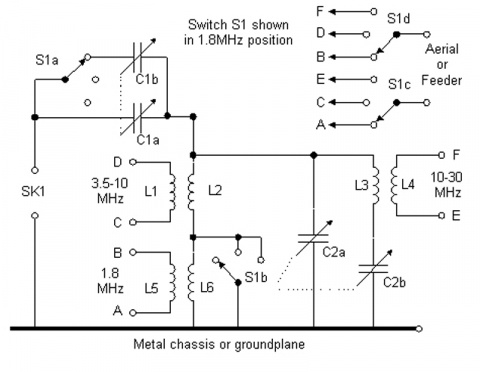
C1A, C1B - dual KPI 250-350 pF max. per section, isolated from the body.
С2А, С2В - dual KPI 350-500 pF max. per section
SK1 - 50 ohm coaxial connector
L1 - 5 turns of wire 1.63 mm, inner diameter 50 mm, gap between turns about 4.2 mm, around L2
L2 - 6 turns of wire 1.63 mm, inner diameter 38 mm, gap between turns about 4.2 mm
L3 - 4 turns of wire 1.63 mm, inner diameter 38 mm, gap between turns about 4.2 mm
L4 - 3 turns of wire 1.63 mm, inner diameter 50 mm, gap between turns about 4.2 mm, around L3
L5 - 12 turns of wire 0.71-1.22 mm, inner diameter 10-12 mm larger than L6, with taps through
every 3 turns, located at the "cold" output L6
L6 - 37 turns of wire 1.63 mm, inner diameter 38 mm, with taps from the 17th, 22nd and 27th turns.
The number of turns of the coils depends on the selected KPI and is selected during setup. Coils are fixed
on the frameworks and fixed with a suitable compound (possible design, see
previous article. Note. transl.)
For the L6 coil, you can use a ceramic or plastic frame.
mounted at right angles to L3/L4 and L5/L6.
Frequency overlap depends on the minimum and maximum capacitance of the KPI and coils, and the possible
the impedance of the matched load depends on the ratio of the turns of each pair of coils and, again, on
KPI. If the minimum SWR is obtained at the maximum C1, then it is necessary to reduce the number of turns
At L1/L4/L5 according to the selected range.
Setting up Z-Match
Even 10 ... 15 years ago, there was practically no problem with the use of matching devices (CS), respectively, there were almost no descriptions of such devices in amateur radio literature.
The point, probably, is that earlier in the USSR, almost everyone used home-made lamp equipment, the output stage of which could be matched with almost anything.
Transistor RAs produce much more harmonics than tube ones. And often a low-quality P-circuit at the output of a transistor RA cannot cope with their filtering. In addition, it must be taken into account that the number of TV channels has increased many times over compared to what it was a few years ago!
The purpose of the matching device
The control system provides the transformation of the output impedance of the transmitter into the impedance of the antenna. It is irrational to use a control system with a tube power amplifier having a P-loop with all three smoothly tunable elements, since the P-loop provides matching in a wide range of output impedances. Only in cases where the elements of the P-loop exclude adjustment, the use of SU is beneficial.
In any case, the SU noticeably reduces the level of harmonics, and its use as a filter is fully justified.
With good tuned resonant antennas and good PA, there is no need to use a matching device. But when the antenna alone operates on several bands, and the RA does not always give out what is needed, the use of the SU gives good results.
Principles of building a matching device
The classical SU has the form shown in Fig. 1. As you can see, it consists of a matching circuit (CS), which is made according to one of the well-known schemes (the CS itself is often called "matching device", "ATU"), an SWR meter, an RF bridge that shows the degree of antenna mismatch, an equivalent antenna R 1, and control loads R2, R3. Without all this "environment" SU is only a chain of coordination, nothing more.
Fig.1
Let's analyze the principle of operation of the device. In the S 1 "Bypass" position, the transmitter output is connected to S2, which makes it possible either to directly connect the antenna, or to turn on one of the load equivalents (R2 or R3) to the output and check the possibility of matching the transmitter with it. In the "Setting" position, the transmitter operates on a matched load. Also, through the resistance R4, the RF bridge is turned on. According to the balance of this bridge, the matching circuit is used to tune the antenna. Resistors R2 and R3 make it possible to check whether it is possible to tune the matching circuit to them. Having configured the CA, turn on the "Work" mode. In this mode, the matching circuit is adjusted a little more to the minimum of the SWR meter readings.
Below we consider the main CAs used in practice.
Matching circuit on a parallel circuit
One of the most efficient and simple CAs is shown in Figure 2. The transmitter is connected via coil L1 and capacitor C1. L1 is from a quarter to a sixth of the number of turns of L2 and is wound in its lower part. L1 must be separated from L2 by good insulation.

Fig.2
In this scheme, the transmitter is connected to the CS only by magnetic flux, and here the issue of lightning protection of the output stage is automatically resolved. Capacitor C1 for operation at 1.8 MHz. should have a maximum capacitance - 1500 pF, and for operation at 28 MHz - 500 pF. C2 and C1 should have the largest possible gap between the plates. The load resistance range is from 10 ohms to several kilo ohms. High efficiency operation is provided in two adjacent bands, such as 1.8 and 3.5 MHz. For efficient operation in several ranges, it is necessary to switch L1 and L2. At low powers (up to 100 W), it is most efficient and easy to make a set of replacement coils and install them using base panels from old radio tubes. Any experiments related to connecting L1 and L2 coils in parallel to reduce their inductance for operation on the HF bands, connecting these coils to the taps, the "cunning" parallel connection of the coils, significantly reduces the efficiency of this DC at HF. The coil data for the circuit in Fig. 2 are shown in Table 1.
Table 1
Although symmetrical antennas are rarely used at present, it is worth considering the possibility of operating this DS on a symmetrical load (Fig. 3).

Fig.3
Its only difference from the circuit in Fig. 2 is that the voltage for the load is removed symmetrically. L1 must be located symmetrically with respect to L2. Capacitors C1 and C2 must be on the same axis. It is necessary to take measures to reduce the influence of the capacitive effect on L2, i.e. it should be far enough from the metal walls. The L2 data for the circuit in Fig. 3 are given in Table 2.
table 2
There are also constructions of a simplified version of this CA.

Fig.4
Figure 4 shows an asymmetric circuit, Figure 5 shows a symmetrical circuit. But, unfortunately, as experience shows, these circuits cannot give such careful coordination as in the case of using capacitors C3 (Fig. 2) or C3.1, C3.2 (Fig. 3).

Fig.5
Particular care must be taken in the construction of multi-band DS operating on this principle (Fig. 6). Due to the decrease in the Q-factor of the coil and the large capacity of the ground taps, the efficiency of such a system in the HF bands is low, but the use of such a system in the 1.8 ... 7 MHz bands is quite acceptable.

Fig.6
Setting up the CA shown in Figure 2 is simple. Capacitor C1 is set to the maximum position, C2 and C3 - to the minimum, then with the help of C2 the circuit is tuned to resonance, and then, increasing the connection with the antenna using C3, they achieve maximum power output to the antenna, while constantly adjusting C2 and, according to opportunities, C1. You should strive to ensure that after setting up the C3 CA has the maximum capacity.
T-chain matching
This scheme (Fig. 7) is widely used when working with asymmetric antennas.

Fig.7
For the normal operation of this DC, a smooth adjustment of the inductance is necessary. Sometimes even half a turn is critical to matching. This limits the use of tapped inductors or requires individual selection of the number of turns for a particular antenna. It is necessary that the capacitance of C1 and C2 to the "ground" be no more than 25 pF, otherwise the efficiency may decrease by 24 ... 28 MHz. It is necessary that the "cold" end of the L1 coil be carefully grounded. This DC has good parameters: efficiency - up to 80% with the transformation of 75 ohms to 750 ohms, the ability to match the load from 10 ohms to several kilo-ohms. With only one variable inductance of 30 μH, you can cover the entire range from 3.5 to 30 MHz, and by connecting C1, C2 constant capacitors of 200 pF in parallel, you can also work at 1.8 MHz.
Unfortunately, variable inductance is expensive and structurally complex. W3TS proposed a switchable "digital inductor" (Figure 8). Using such an inductance, with the help of switches, you can visually set its desired value.
Another attempt to simplify the design was made by AEA by making a matching device according to the scheme shown in Fig. 9. Indeed, the circuits in Fig. 7 and Fig. 9 are equivalent. But structurally it is much easier to use one grounded high-quality capacitor instead of two isolated ones, and replace the expensive variable inductance with cheap permanent inductors with taps. This DS worked well from 1.8 to 30 MHz, transforming 75 ohms to 750 ohms and 15 ohms. But when working with real antennas, the discreteness of inductance switching sometimes affected. In the presence of 18, and preferably 22 position switches, this CA can be recommended for practical implementation. In this case, it is necessary to reduce the length of the coil leads to the switch to a minimum. Switches for 11 AEA AT-30 TUNER L1-L2-25 Turns, diam. coils 45 mm winding pitch 4 mm taps from each turn along the length of 10 turns then after 2 turns of positions make it possible to make a CS only for working on a part of the amateur bands - from 1.8 to 7 or from 10 to 28 MHz.

Fig.9
The coil is structurally convenient to perform as shown in Fig. 10. Its frame is a bar of double-sided fiberglass with cuts for coil turns. A switch is installed on this bar (for example, 11P1N). The taps from the coil go to the switch on both sides of the fiberglass strip.

Fig.10
When working with symmetrical antennas, together with a T-shaped matching device, a balancing transformer 1:4 or 1:6 is used at the output of the DS. Such a decision cannot be considered effective, because. many balanced antennas have a large reactive component, and ferrite transformers work very poorly with reactive loads. In this case, it is necessary to apply measures to compensate for the reactive component or use a DS (Fig. 3).
U-shaped matching scheme
U-shaped CS (or P-loop), the scheme of which is given in fig. 11 is widely used in amateur radio practice.

Fig.11
In real conditions, when the transmitter output is 50 ... 75 Ohm, and matching must be done in a wide range of load resistances, the parameters of the P-loop change tenfold. For example, at 3.5 MHz with Rin \u003d Rn \u003d 75 Ohm, the inductance L1 is approximately 2 μH, and C1, C2 - 2000 pF each, and with Rin \u003d 75 Ohm and RH a few kiloohms, the inductance L1 is approximately 20 μH, the capacitance C1 is about 2000 pF, and C2 is tens of picofarads. Such large variations in the values of the elements used limit the use of the P-loop as a CS.
It is desirable to use a variable inductance. Capacitor Cl may have a small gap, and C2 should have a gap of at least 2 mm for every 200 watts of power.
Improving the efficiency of the matching device
To increase the efficiency of the transmitter, especially when using random antennas, a device called "artificial earth" helps. This device is effective when using random antennas and with poor radio grounding. This device brings to a resonant state the grounding system of the radio station (in the simplest case, a piece of wire). Since the parameters of the ground are included in the parameters of the antenna system, improving the efficiency of the ground improves the performance of the antenna.
Conclusion
The matching device should be used no more than it is really needed. You should choose the type of SU that you need. For example, it makes no sense to manufacture a broadband device for operation in the range of 1.8 ... 30 MHz, if you really do not "build" antennas for 1 ... 2 ranges, or surrogate antennas are used on these ranges. Here it is much more efficient to perform its own separate SU for each range. But of course, if you are using a transceiver with a non-adjustable output and most of your antennas are surrogate, then an all-band DC is needed here.
All of the above applies to the "artificial earth" device.

Fig.12
Literature
1. Podgorny I. (EW1MM). HF ground/Ham radio HF and VHF. - 1995. - No. 9.
2. Grigorov I. (RK3ZK). The matching device on a coaxial cable / Radio amateur. - 1995. - No. 7.
3. Podgorny I. (UC2AGL). Antenna tuner / Radio amateur. -1994.-№2.
4. Podgorny I. (UC2AGL). Antenna tuner / Radio amateur. -1991.-№1.
5. Grigorov I. (UZ3ZK). Universal matching device // Radio amateur. - 1993. - No. 11.
6. Padalko S. (RA6LEW). Antenna switching and matching device / Radio amateur. - 1991. - No. 12.
7. Orlov V. (UT5JAM). All-band matching device for LW / Radio amateur. -1992. - No. 10.
8. Villemagne P. (F9HY). Coordinating device for antennas of the LEVY/ /radioamateur type. - 1992. - No. 10.
9. Podgorny I. (EW1MM). Universal antenna matching device / Radio amateur. - 1994. - No. 8.
Antenna matching devices. Tuners
ACS. Antenna tuners. Schemes. Reviews of branded tuners
In amateur radio practice, it is not so common to find antennas in which the input impedance is equal to the wave impedance of the feeder, as well as the output impedance of the transmitter.
In the vast majority of cases, such a match cannot be detected, so you have to use specialized antenna matching devices. The antenna, feeder and output of the transmitter (transceiver) are part of a single system in which energy is transmitted without any loss.
Do you need an antenna tuner?
From Alexey RN6LLV:
In this video, I will tell beginner radio amateurs about antenna tuners.
What is an antenna tuner for, how to correctly use it in conjunction with an antenna, and what are the typical misconceptions about using a tuner among radio amateurs.
We are talking about a finished product - a tuner (manufactured by a company), if you want to build your own, save money or experiment, then you can skip the video and see further (below).
Quite below - reviews of branded tuners.
Antenna tuner, antenna tuner buy, digital tuner + with antenna, automatic antenna tuner, mfj antenna tuner, HF antenna tuner, antenna tuner + DIY, HF antenna tuner, antenna tuner circuit, a LDG antenna tuner, SW meter
All band matching device (with separate coils)
Variable capacitors and a biscuit switch from R-104 (BLS unit).
In the absence of these capacitors, it is possible to use 2-section ones, from broadcast radio receivers, by turning on the sections in series and isolating the body and the axis of the capacitor from the chassis.
You can also use a conventional biscuit switch, replacing the axis of rotation with a dielectric one (fiberglass).
Data of contour coils of the tuner and accessories:
L-1 2.5 turns, AgCu wire 2 mm, coil outer diameter 18 mm.
L-2 4.5 turns, AgCu wire 2 mm, coil outer diameter 18 mm.
L-3 3.5 turns, AgCu wire 2 mm, coil outer diameter 18 mm.
L-4 4.5 turns, AgCu wire 2 mm, coil outer diameter 18 mm.
L-5 3.5 turns, AgCu wire 2 mm, coil outer diameter 18 mm.
L-6 4.5 turns, AgCu wire 2 mm, coil outer diameter 18 mm.
L-7 5.5 turns, PEV wire 2.2 mm, coil outer diameter 30 mm.
L-8 8.5 turns, PEV wire 2.2 mm, coil outer diameter 30 mm.
L-9 14.5 turns, PEV wire 2.2 mm, coil outer diameter 30 mm.
L-10 14.5 turns, PEV wire 2.2 mm, coil outer diameter 30 mm.
Source: http://ra1ohx.ru/publ/schemy_radioljubitelju/soglasujushhie_ustrojstva_antennye_tjunery/vsediapazonnoe_su_s_razdelnymi_katushkami/19-1-0-652
Simple antenna matching LW - "long wire"
I had to urgently launch 80 and 40 meters in a strange house, there is no access to the roof, and there is no time to install an antenna.
I threw a vole a little over 30 m from the balcony of the third floor onto a tree. I took a piece of plastic pipe with a diameter of about 5 cm, wound about 80 turns of wire with a diameter of 1 mm. From below, he made taps every 5 turns, and from above, after 10 turns. I assembled such a simple matching device on the balcony.
I hung a field strength indicator on the wall. I switched on the range of 80 m in QRP mode, picked up a tap from the top of the coil and tuned my "antenna" with a capacitor to resonance at the maximum of the indicator readings, then picked up a tap at the bottom of the FAC.
There was no time, and therefore I did not set the biscuits. and "ran" along the turns with the help of crocodiles. And the whole European part of Russia answered me to such a surrogate, especially at 40 m. Even no one paid attention to my vole. This is of course not a real antenna, but the information will be useful.
RW4CJH info - qrz.ru
Coordinating device for low-frequency antennas
Radio amateurs living in multi-storey buildings often use loop antennas on the low bands.
Such antennas do not require high masts (they can be pulled between houses at a relatively high height), good grounding, a cable can be used to power them, and they are less susceptible to interference.
In practice, the variant of the frame in the form of a triangle is convenient, since its suspension requires a minimum number of attachment points.
As a rule, most shortwavers tend to use such antennas as multi-band ones, but in this case it is extremely difficult to ensure an acceptable antenna-to-feeder matching on all operating bands.
For over 10 years I have used a Delta antenna on all bands from 3.5 to 28 MHz. Its features are the location in space and the use of a matching device.
Two vertices of the antenna are fixed at the level of the roofs of five-story buildings, the third (open) - on the balcony of the 3rd floor, both of its wires are introduced into the apartment and connected to a matching device, which is connected to the transmitter by a cable of arbitrary length.
In this case, the perimeter of the antenna frame is about 84 meters.
Schematic diagram of the matching device is shown in the figure on the right.
The matching device consists of a broadband balancing transformer T1 and a P-loop formed by a coil L1 with taps and capacitors connected to it.
One of the embodiments of the transformer T1 is shown in fig. left.
Details. Transformer T1 is wound on a ferrite ring with a diameter of at least 30 mm with a magnetic permeability of 50-200 (non-critical). The winding is carried out simultaneously with two PEV-2 wires with a diameter of 0.8 - 1.0 mm, the number of turns is 15 - 20.
The P-loop coil with a diameter of 40 ... 45 mm and a length of 70 mm is made of bare or enameled copper wire with a diameter of 2-2.5 mm. Number of turns 13, taps from 2; 2.5; 3; 6 turns, counting from the left according to the L1 output circuit. Adjusted capacitors of the KPK-1 type are assembled on studs in packs of 6 pcs. and have a capacitance of 8 - 30 pF.
Setting. To configure the matching device, it is necessary to include an SWR meter in the cable break. On each range, the matching device is adjusted to the minimum SWR using tuned capacitors and, if necessary, by selecting the tap position.
Before setting up the matching device, I advise you to disconnect the cable from it and set up the output stage of the transmitter by connecting a load equivalent to it. After that, you can restore the connection of the cable to the matching device and perform the final tuning of the antenna. It is expedient to divide the range of 80 meters into two sub-bands (CW and SSB). When tuning, it is easy to achieve an SWR close to 1 on all ranges.
This system can also be used on the WARC bands (you just need to pick up taps) and on 160 m, respectively, by increasing the number of coil turns and the antenna perimeter.
It should be noted that all of the above is true only when the antenna is directly connected to the matching device. Of course, this design will not replace the "wave channel" or "double square" on 14 - 28 MHz, but it is well tuned on all bands and removes many problems for those who are forced to use one multi-band antenna.
Instead of switched capacitors, KPIs can be used, but then you will have to adjust the antenna each time you switch to a different range. But, if at home this option is inconvenient, then in the field or camping conditions it is fully justified. Reduced versions of the "delta" for 7 and 14 MHz, I have repeatedly used when working in the "field". In this case, two peaks were attached to trees, and the power supply was connected to a matching device lying directly on the ground.
In conclusion, I can say that using only a transceiver with an output power of about 120 W without any power amplifiers, with the described antenna on the 3.5 bands; 7 and 14 MHz never had any problems, while I work, as a rule, on a general call.
S. Smirnov, (EW7SF)
Construction of a simple antenna tuner
Antenna tuner design from RZ3GI
I propose a simple version of the antenna tuner, assembled according to the T-shaped scheme.
Tested with FT-897D and IV antenna at 80, 40 m.
Built on all HF bands.
Coil L1 is wound on a mandrel 40 mm with a pitch of 2 mm and has 35 turns, a wire with a diameter of 1.2 - 1.5 mm, taps (counting from the "ground") - 12, 15, 18, 21, 24, 27, 29, 31, 33, 35 turns.
Coil L2 has 3 turns on a 25 mm mandrel, winding length 25 mm.
Capacitors C1, C2 with C max \u003d 160 pF (from the former VHF station).
SWR meter is applied built-in (in FT - 897D)
Antenna Inverted Vee for 80 and 40 meters - is built on all ranges.
Yuri Ziborov RZ3GI.
Tuner photo:


"Z-match" antenna tuner
Under the name "Z-match" a great many designs and schemes are known, I would even say more designs than schemes.
The basis of the circuit design from which I started is widely distributed on the Internet and offline literature, everything looks something like this (see on the right):
And so, considering many different diagrams, photographs and notes posted on the network, I had the idea to assemble an antenna tuner for myself.
My hardware magazine was at hand (yes, yes, I am an adherent of the old school - old school, as the youth expresses it) and on its page a diagram of a new device for my radio station was born.
I had to withdraw a page from the magazine "to attach to the case":
It is noticeable that there are significant differences from the original. I did not use inductive coupling with an antenna with its symmetry, an autotransformer circuit is enough for me. it is not planned to feed the antennas with a symmetrical line. For the convenience of setting up and monitoring antenna-feeder structures, I added an SWR meter and a wattmeter to the general circuit.
Having finished with the calculations of the circuit elements, you can start layout:


In addition to the case, some radio elements have to be made, one of the few radio components that a radio amateur can make himself is an inductor:
And here is the result, inside and out:


Scales and designations have not yet been applied, the front panel is faceless and not informative, but the main thing WORKS !! And this is good…
R3MAV. info - r3mav.ru
Matching device by analogy Alinco EDX-1
This antenna matching circuitry is borrowed from the proprietary Alinco EDX-1 HF ANTENNA TUNER that worked with my DX-70.
Details:
C1 and C2 300 pf. Air dielectric capacitors. The pitch of the plates is 3 mm. Rotor 20 plates. Stator 19. But you can use dual KPIs with a plastic dielectric from old transistor receivers or with an air dielectric 2x12-495 pF. (as in the picture)
You ask: "Won't it sew?". The fact is that the coaxial cable is soldered directly to the stator, and this is 50 ohms, and where should a spark slip through with such a low resistance?
It is enough to stretch a line 7-10 cm long from the capacitor with a "bare" wire, as it burns with a blue flame. To remove static, capacitors can be shunted with a 15 kOhm 2 W resistor. (quote from "UA3AIC Design Power Amplifiers").
L1 - 20 turns of silver-plated wire D=2.0 mm, frameless D=20 mm. Branches, counting from the upper end according to the diagram:
L2 25 turns, PEL 1.0, wound on two ferrite rings folded together, D outer = 32 mm, D inner = 20 mm.
Thickness of one ring = 6 mm.
(For 3.5 MHz).
L3 28 turns, and everything else is the same as L2 (For 1.8 MHz).
But, unfortunately, at that time I could not find suitable rings and did this: I machined rings from plexiglass and wound wires around them until they were filled. I connected them in series - this turned out to be the equivalent of L2.
On a mandrel with a diameter of 18 mm (you can use a plastic sleeve from a 12-gauge hunting rifle), a coil to coil wound 36 turns - this turned out to be an analogue of L3.
Everything is visible in the picture. And a SWR meter too. SWR meter from the description of Tarasov A. UT2FW "HF-VHF" No. 5 for 2003.
Antenna matching device delta, square, trapezoid
Among radio amateurs, a loop antenna with a perimeter of 84 m is very popular. Basically, it is tuned to the 80M range and, with a slight compromise, it can be used on all amateur radio bands. Such a compromise can be accepted if we are working with a tube power amplifier, but if we have a more modern transceiver, things will not work there. You need a matching device that sets the SWR on each band, corresponding to the normal operation of the transceiver. HA5AG told me about a simple matching device and sent me a brief description of it (see picture). The device is designed for loop antennas of almost any shape (delta, square, trapezoid, etc.)
Short description:
The author's matching device was tested on an antenna, the shape of which is almost square, installed at a height of 13 m in a horizontal position. The input impedance of this QUAD antenna on the 80 m band is 85 ohms, and on the harmonics 150 - 180 ohms. The wave impedance of the supply cable is 50 ohms. The task was to match this cable with the input impedance of the antenna 85 - 180 ohms. For matching, a transformer Tr1 and a coil L1 were used.
In the range of 80 m, using the relay P1, we short-circuit the coil n3. In the cable circuit, the coil n2 remains on, which, with its inductance, sets the input impedance of the antenna to 50 ohms. On other bands, P1 is disabled. Coils n2 + n3 (6 turns) are included in the cable circuit and the antenna matches 180 ohms to 50 ohms.
L1 - extension coil. It will find its application on the 30 m band. The fact is that the third harmonic of the 80 m band does not coincide with the allowed frequency range of the 30 m band. (3 x 3600 kHz = 10800 kHz). Transformer T1 matches the antenna at 10500 kHz, but this is still not enough, you need to turn on the L1 coil, and in this inclusion the antenna will already resonate at a frequency of 10100 kHz. To do this, with the help of K1, we turn on the relay P2, which at the same time opens its normally closed contacts. L1 can still serve in the range of 80 m, when we want to work in the telegraph section. On the 80 m-ohm band, the resonance band of the antenna is about 120 kHz. To shift the resonance frequency, you can turn on L1. The included L1 coil significantly reduces the SWR at the 24 MHz frequency, as well as at the 10 m band.
The matching device performs three functions:
1. Provides symmetrical power supply to the antenna, since the antenna fabric is isolated in RF from the "ground" through the coils of the transformer Tr1 and L1.
2. Matches the impedance as described above.

3. Using the coils n2 and n3 of the transformer, Tr1 sets the antenna resonance in the appropriate, allowed frequency bands by range. A little more about this: If the antenna is initially tuned to a frequency of 3600 kHz (without turning on the matching device), then on the 40 m band it will resonate at 7200 kHz, at 20 m at 14400 kHz, and at 10 m already at 28800 kHz. This means that the antenna must be lengthened in each range, and at the same time, the higher the frequency of the range, the more it requires lengthening. Here, just such a coincidence is used to match the antenna. Transformer coils n2 and n3, T1 with a certain inductance, the more it lengthens the antenna, the higher the frequency of the range. In this way, on 40 meters the coils are lengthened to a very small extent, and on 10 meters already to a large extent. A properly tuned antenna is resonated by the matching device on each band in the region of the first 100 kHz frequency.
The position of the switches K1 and K2 by ranges are shown in the table (on the right):
If the input impedance of the antenna on the 80 m band is not set within 80 - 90 Ohm but within 100 - 120 Ohm, then the number of turns of the coil n2 of the transformer T1 must be increased by 3, and if the resistance is even greater, so by 4. The parameters of the remaining coils remain without changes.
Translation: UT1DA source - (http://ut1da.narod.ru) HA5AG
SWR meter with matching device
On fig. on the right is a schematic diagram of the device, which includes an SWR meter, with which you can tune the CB antenna, and a matching device that allows you to bring the resistance of the tuned antenna to Ra \u003d 50 Ohm.
Elements of the SWR meter: T1 - antenna current transformer wound on a ferrite ring M50VCh2-24 12x5x4 mm. Its winding I is a conductor with antenna current threaded into the ring, winding II is 20 turns of wire in plastic insulation, it is wound evenly around the entire ring. Capacitors C1 and C2 are of the KPK-MN type, SA1 is any toggle switch, RA1 is a 100 μA microammeter, for example, M4248.
Elements of the matching device: coil L1 - 12 turns of PEV-2 0.8, inner diameter - 6, length - 18 mm. Capacitor C7 - type KPK-MN, C8 - any ceramic or mica, operating voltage of at least 50 V (for transmitters with a power of not more than 10 watts). Switch SA2 - PG2-5-12P1NV.
To adjust the SWR meter, its output is disconnected from the matching circuit (in t. A) and connected to a 50-ohm resistor (two MLT-2 100 Ohm resistors connected in parallel), and a CB radio station is connected to the input. In the direct wave measurement mode - in the one indicated in fig. 12.39 position SA1 - the device should show 70 ... 100 μA. (This is for a 4 W transmitter. If it is more powerful, then "100" on the PA1 scale is set differently: by selecting a resistor shunting PA1 with a shorted resistor R5.)
By switching SA1 to another position (reflected wave control), by adjusting C2, zero readings of PA1 are achieved.
Then the input and output of the SWR meter are reversed (the SWR meter is symmetrical) and this procedure is repeated, setting C1 to the "zero" position.
This completes the SWR meter setting, its output is connected to the seventh turn of the L1 coil.
The SWR of the antenna path is determined by the formula: SWR = (A1 + A2) / (A1-A2), where A1 is the readings of PA1 in the direct wave measurement mode, and A2 is the reverse one. Although it would be more correct to speak here not about the SWR, as such, but about the magnitude and nature of the antenna impedance given to the antenna connector of the station, about its difference from the active Ra = 50 Ohm.
The antenna path will be adjusted if the minimum possible SWR is obtained by changing the length of the vibrator, counterweights, sometimes the length of the feeder, the inductance of the extension coil (if any), etc.
Some inaccuracy in antenna tuning can be compensated by detuning the L1C7C8 contour. This can be done with a capacitor C7 or by changing the inductance of the circuit - for example, by introducing a small carbonyl core into L1.
As the experience of tuning and matching CB antennas of various configurations and sizes (0.1 ... 3L) shows, under control and with the help of this device it is easy to obtain SWR = 1 ... 1.2 in any part of this range.
Radio, 1996, 11
Simple Antenna Tuner
To match the transceiver with various antennas, you can successfully use the simplest manual tuner, the diagram of which is shown in the figure. It covers the frequency range from 1.8 to 29 MHz. In addition, this tuner can work as a simple antenna switch, which also has a load equivalent. The power supplied to the tuner depends on the gap between the plates of the variable capacitor C1 used - the larger it is, the better. With a gap of 1.5-2 mm, the tuner could withstand power up to 200 W (maybe more - my TRX power was not enough for further experiments). One of the SWR meters can be turned on at the tuner input to measure the SWR, although this is not necessary when the tuner works together with imported transceivers - they all have a built-in SWR measurement (SVR) function. Two (or more) PL259 type RF connectors allow you to connect the antenna selected using the S2 “Antenna Switch” switch to work with the transceiver. The same switch has an "Equivalent" position, in which the transceiver can be connected to a dummy load with a resistance of 50 ohms. With relay switching, the Bypass mode can be enabled and the antenna or equivalent (depending on the position of the S2 antenna switch) will be directly connected to the transceiver.
As C1 and C2, standard KPE-2 with a 2x495 pF air dielectric from industrial household receivers are used. Their sections are pulled through one plate. In C1, two sections connected in parallel are involved. It is mounted on a 5 mm thick Plexiglas plate. In C2 - one section is involved. S1 - 6-position HF switch (2N6P ceramic biscuits, their contacts are connected in parallel). S2 - the same, but with three positions (2N3P, or more positions depending on the number of antenna connectors). Coil L2 - wound with bare copper wire d = 1mm (preferably silver plated), 31 turns in total, winding with a small pitch, outer diameter 18 mm, taps from 9 + 9 + 9 + 4 turns. Coil L1 - too, but 10 turns. Coils are installed mutually perpendicular. L2 can be soldered with leads to the contacts of the biscuit switch by bending the coil in a half ring. The tuner is mounted with short thick (d = 1.5-2 mm) pieces of bare copper wire. Relay type TKE52PD from radio station R-130M. Naturally, the best option is to use higher-frequency relays, for example, of the REN33 type. The voltage for supplying the relay was obtained from a simple rectifier assembled on a TVK-110L2 transformer and a KTs402 (KTs405) diode bridge or the like. The relay is switched by the S3 "Bypass" toggle switch of the MT-1 type, installed on the front panel of the tuner. The La lamp (optional) serves as a power indicator. It may turn out that there is not enough capacitance C2 in the low-frequency ranges. Then, in parallel with C2, you can use relay P3 and toggle switch S4 to connect either its second section or additional capacitors (select 50 - 120 pF - shown in the diagram by a dotted line).
According to the recommendation, the KPI axles are connected to the control knobs through segments of a durite gas hose that serve as insulators. For their fixation, water clamps d=6 mm were used. The tuner was made in a case from the Electronics-Kontur-80 kit. Slightly larger body sizes than the tuner described in, leave enough room for improvements and modifications to this circuit. For example, a low-pass filter at the input, a 1:4 matching balun at the output, a built-in SWR meter, and others. For efficient operation of the tuner, one should not forget about its good grounding.
Simple tuner for balanced line tuning
The figure shows a diagram of a simple tuner for matching a balanced line. An LED is used as a setting indicator.
In amateur practice, it is not so common to find antennas in which the input impedance is equal to the feeder, as well as the output impedance of the transmitter. In the vast majority of cases, such a match cannot be detected, so specialized matching devices must be used. Antenna, feeder, as well as the output of the transmitter are included in a single system in which energy is transmitted without any loss.
How to do it?
To accomplish this rather complicated task, it is necessary to use matching devices in two main places - this is the point where the antenna connects to the feeder, and also the point where the feeder connects to the transmitter output. The most widespread today are specialized transforming devices, ranging from oscillatory resonant circuits to coaxial transformers, made in the form of separate pieces of a coaxial cable of the required length. All of these matchers are used to match impedances, ultimately minimizing overall transmission line loss and, more importantly, reducing out-of-band emissions.
Resistance and its features
In the vast majority of cases, the standard output impedance in modern broadband transmitters is 500 m. It is worth noting that many coaxial cables used as a feeder also differ in the standard value of wave impedance at the level of 50 or 750 m. If we consider antennas for which matching devices can be used, then, depending on the design and type, the input impedance in them has a fairly wide range of values, ranging from a few ohms to hundreds and even more.
It is known that in single-element antennas, the input impedance at the resonant frequency is practically active, and the more the transmitter frequency differs from the resonant one in one direction or another, the more the reactive component of an inductive or capacitive nature will appear in the input impedance of the device itself. At the same time, multi-element antennas have an input impedance at the resonant frequency, which has a complex character due to the fact that various passive elements contribute to the formation of the reactive component.
If the input impedance is active, it can be matched to the impedance using a specialized antenna matching device. It should be noted that the losses here are practically negligible. However, as soon as a reactive component begins to form in the input impedance, the matching procedure will become more and more complex, and an increasingly complex antenna matching device will need to be used, the capabilities of which will compensate for unwanted reactivity, and it should be located directly at the point nutrition. If reactivity is not compensated for, this will adversely affect the SWR in the feeder and will also significantly increase the overall losses.
Does it need to be done?

An attempt to fully compensate for reactivity at the lower end of the feeder is unsuccessful, since it is limited by the characteristics of the device itself. Any changes in the frequency of the transmitter within the narrow sections of the amateur bands will ultimately not lead to the appearance of a significant reactive component, as a result of which there is often no need to compensate for it. It is also worth noting that the correct design of multi-element antennas also does not provide for a large reactive component of the available input impedance, which does not require its compensation.
On the air, you can often find various disputes about the role and purpose of the matching device for the antenna (“long wire” or another type) in the process of matching the transmitter with it. Some have rather high hopes for it, while others simply consider it an ordinary toy. That is why you need to correctly understand how an antenna tuner can really help in practice, and where its use will be superfluous.
What it is?

First of all, you need to correctly understand that the tuner is a high-frequency resistance transformer, with the help of which, if necessary, it will be possible to compensate for reactivity of an inductive or capacitive nature. Consider a very simple example:
A split vibrator, which at the resonant frequency has an active input impedance of 700 m, and at the same time it is used with a transmitter, having an input impedance of about 500 m. Tuners are installed at the output of the transmitter, and in this situation they will be for any antenna (including the "long cable") matching devices between the transmitter and the feeder, without any difficulties coping with their main task.
If in the future the transmitter is tuned to a frequency that differs from the resonant frequency of the antenna, then in this case, reactivity may appear in the input resistance of the device, which subsequently almost immediately begins to appear at the lower end of the feeder. In this case, the matching device "P" of any series will also be able to compensate for it, and the transmitter will again receive consistency with the feeder.
What will be at the output where the feeder connects to the antenna?
If you use the tuner exclusively at the output of the transmitter, then in this case it will not be possible to provide full compensation, and various losses will begin to occur in the device, since there will be incomplete matching. In such a situation, it will be necessary to use another one connecting between the antenna and the feeder, which will completely correct the situation and provide reactivity compensation. In this example, the feeder acts as a matched transmission line having an arbitrary length.
One more example

The loop antenna, which has an active input impedance of about 1100 m, must be matched to the transmission line at 50 ohms. The transmitter output in this case is 500 m.
Here you will need to use a matching device for the transceiver or antenna, which will be installed at the point where the feeder is connected to the antenna. In the vast majority of cases, many hobbyists prefer to use various types of RF transformers equipped with ferrite cores, but in fact, a quarter-wave coaxial transformer, which can be made from a standard 75-ohm cable, is a more convenient solution.
How to implement it?
The length of the cable section used should be calculated using the formula A / 4 * 0.66, where A is the wavelength, and 0.66 is the velocity factor used for the vast majority of modern coaxial cables. The HF antenna matching devices in this case will be connected between the 50-ohm feeder and the antenna input, and if they are rolled into a bay with a diameter of 15 to 20 cm, then in this case it will also act as a balancing device. The feeder will be fully automatically coordinated with the transmitter, as well as if their resistances are equal, and in such a situation it will be possible to completely abandon the services of a standard antenna tuner.
Another variant

For such an example, we can consider another optimal matching method - using a multiple of half a wave or a half-wave coaxial cable, in principle, with any wave impedance. It is included between the tuner located near the transmitter and the antenna. In this case, the input impedance of the antenna, which has a value of 110 ohms, is transferred to the lower end of the cable, after which, using an antenna matching device, it is transformed into a resistance of 500 m. In this case, full matching of the transmitter with the antenna is provided, and the feeder is used as a repeater .
In more severe situations, when the input impedance of the antenna is inappropriate for the wave impedance of the feeder, which, in turn, does not correspond to the output impedance of the transmitter, two HF antenna matching devices are required. In this case, one is used at the top to match the feeder to the antenna, while the other is used to match the feeder to the transmitter at the bottom. At the same time, there is no way to make some matching device with your own hands, which can be used alone to match the entire circuit.
The emergence of reactivity will make the situation even more complicated. In this case, HF band matching devices will significantly improve the matching of the transmitter with the feeder, thus providing a significant simplification of the operation of the final stage, but you should not expect more from them. Due to the fact that the feeder will be mismatched with the antenna, losses will appear, so the efficiency of the device itself will be underestimated. An activated SWR meter installed between the tuner and the transmitter will ensure that the SWR = 1 is fixed, and this effect cannot be achieved between the feeder and the tuner, since there is a mismatch.
Output
The benefit of the tuner is that it allows you to maintain the optimal mode of the transmitter in the process of working on an inconsistent load. But at the same time, an improvement in the efficiency of any antenna (including the “long wire”) cannot be ensured - the matching devices are powerless if it is mismatched with the feeder.
The P-loop, which is used in the output stage of the transmitter, can also be used as an antenna tuner, but only if there is an operational change in the inductance and each capacitance. In the vast majority of cases, both manual and automatic tuners are resonant contour tunable devices, regardless of whether they are assembled at the factory or someone decided to make a matching device for the antenna with their own hands. There are two or three regulating elements in manual ones, and they themselves are not operational in operation, while automatic ones are expensive, and for work at serious powers, their cost can be extremely high.
Broadband matching device

Such a tuner satisfies the predominant majority of variations in which it is necessary to ensure the matching of the antenna with the transmitter. Such equipment is quite effective in the process of working with antennas used on harmonics, if the feeder is a half-wave repeater. In this situation, the input impedance of the antenna is different on different bands, but the tuner allows for easy matching with the transmitter. The proposed device can easily operate at transmitter powers up to 1.5 kW in the frequency band from 1.5 to 30 MHz. Such a device can be made even with your own hands.

The main elements of the tuner are an RF autotransformer on the UNT-35 TV from the deflecting system, as well as a switch designed for 17 positions. It is possible to use cone rings from models UNT-47/59 or any other. There are 12 turns in the winding, which are wound into two wires, while the beginning of one is combined with the end of the second. In the diagram and in the table, the numbering of the turns is through, while the wire itself is stranded and enclosed in fluoroplastic insulation. In terms of insulation, the wire diameter is 2.5 mm, providing taps from each turn, starting from the eighth, if counting from the grounded end.
The autotransformer is installed as close as possible to the switch, while the connecting conductors between them must have a minimum length. It is possible to use a switch with 11 positions if the design of the transformer with a not so large number of taps is saved, for example, from 10 to 20 turns, but in this situation the resistance transformation interval will also decrease.
Knowing the exact value of the input impedance of the antenna, such a transformer can be used to match the antenna to a 50 or 750 m feeder, using only the most necessary taps. In such a situation, it is placed in a special moisture-proof box, after which it is filled with paraffin and placed directly at the feed point of the antenna. By itself, the matching device can be performed as an independent design or included in a special antenna-switching unit of some radio station.
For clarity, the label mounted on the switch handle shows the amount of resistance that corresponds to this position. To ensure full compensation of the reactive inductive component, it is possible to subsequently connect a variable capacitor.
The table below clearly indicates how the resistance depends on the number of turns you have made. In this case, the calculation was carried out based on the ratio of resistances, which is in quadratic dependence on the total number of turns made.