The magnetic loop indoor antenna is a great alternative to the classic outdoor antenna. Such designs allow transmitting signals up to 80 m. Coaxial cable is most often used for their manufacture.
Classic version of the magnetic loop antenna
A frame magnetic installation is a subtype of small-sized amateur antennas that can be installed anywhere in a settlement. Under the same conditions, the frames show a more stable result than analogues.
In home practice, the most successful models of popular manufacturers are used. Most of the circuits are found in the amateur radio engineering literature.

Indoor coaxial magnetic loop antenna
DIY antenna assembly
Materials for making
The main element is several types of coaxial cable, 12 m and 4 m long. To build a working model, you also need wooden slats, a 100 pF capacitor and a coaxial connector.
Assembly
A magnetic loop antenna is constructed without special training and knowledge of technical literature. By adhering to the assembly order, you can get a working device the first time:
- connect wooden planks with a cross;
- cut grooves in the planks, the depth corresponding to the radius of the conductor;
- drill holes on the strips at the base of the cross to secure the cable. Cut three grooves between them.
Accurate dimensional control allows you to build a structure with high radio frequency reception.
Magnetic frame shape
A coaxial magnetic antenna is a loop of conductor that connects to a capacitor. The loop is usually circular. This is because this shape increases the efficiency of the structure. The area of this figure is the largest in comparison with the area of other geometric bodies, therefore, the signal coverage will be increased. Manufacturers of goods for radio amateurs produce precisely round frames.

Installation of the structure on the balcony
In order for the devices to work at a specific wavelength range, loops of various diameters are constructed.
There are also models in the form of triangles, squares and polygons. The use of such structures is due in each case to different factors: the location of the device in the room, compactness, etc.
Round and square frames are considered single-turn, because the conductor is not twisted. Today, special programs such as KI6GD allow calculating the characteristics of single-turn antennas only. This type has proven itself well for high-frequency operation. Their main disadvantage is their large size. Many professionals tend to work at low frequencies, which is why the magnetic loop installation is so popular.
Comparative calculations of several circuits with one, two or more turns, under similar operating conditions, showed the dubious efficiency of multi-turn structures. The increase in turns is most advisable only to reduce the size of the entire device. In addition, to implement this scheme, an increase in cable consumption is necessary, therefore, the cost of homemade products unjustifiably increases.
Magnetic frame canvas
For maximum efficiency of the installation, one condition must be achieved: the resistance of losses in the frame fabric must be comparable to the value of the radiation resistance of the entire structure. For thin copper tubes, this condition is easily met. For coaxial cables of large diameter, this effect is more difficult to achieve due to the high resistance of the material. In practice, both types of structures are used, since other types work much worse.
Receiving frames
If the device performs exclusively the function of a receiver, then ordinary capacitors with solid dielectrics can be used for its operation. To reduce dimensions, the receiving frames are multi-turn (made of thin wire).
Such designs are not suitable for transmitting devices, since the action of the transmitter will work to heat the installation.
Coaxial cable braid
The braiding of the magnetic frame provides greater efficiency than copper tubes and thickening of the conductor diameter. Models in a black plastic shell are not suitable for home experiments, because it contains a large amount of soot. During operation, metal parts, with strong heating of the shell, emit chemical compounds harmful to humans. In addition, this feature reduces the transmission signal.

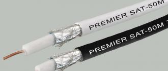
Coaxial cable SAT-50M made in Italy
This type of coaxial cable is only suitable for large antennas because their radiation resistance of the conductor fully compensates for the input resistance.
Impact of external factors
Due to the physical properties of coaxial cables, antennas are not affected by temperature and precipitation. Only the shell created by external factors - rain, snow, ice, lends itself to negative consequences. water has large losses at high frequencies in comparison with cable. As practice shows, it is possible to use such structures on balconies for several decades. Even in severe frosts, there is no significant deterioration in reception.
To increase the reception, magnetic devices from a coaxial cable are best placed in rooms or places with reduced exposure to precipitation: under the canopies, on the protected parts of open balconies. Otherwise, the device will work primarily to heat the environment, and only then to receive and transmit signals.
The main condition for stable operation is the protection of the capacitor from external influences - mechanical, weather, etc. With prolonged exposure to external factors due to high-frequency voltage, an arc may form, which, if overheated, quickly leads to a taps from the circuit or failure of this part.
The frames for high-frequency ranges are horizontal. For low-frequency ones, with a height of more than 30 m, it is advisable to build vertical structures. For them, the installation height does not affect the reception quality.
Device location
If this mechanism is located on the roof, then one condition must be provided - this antenna must be higher than all the others. In practice, perfect placement is often not possible. The magnetic frame installation is rather unpretentious to the close location of third-party objects and structures - ventilation towers, etc.
It will be correct to place the core on the roof far away so that there is no signal absorption by large models. In view of this, when installed on a balcony, its efficiency decreases. This arrangement is justified in cases where conventional receivers do not work correctly.
Synchronization of frame and cable
Matching of parts is achieved by placing a small inductive loop into a large one. For balanced communication, a special balancing transformer is included in the device. For unbalanced, connect the cable directly. The antenna is grounded at the point where the loop is attached to the base of the large circle. The deformation of the loop helps to achieve a more accurate adjustment of the device.

Modification of a device from a coaxial cable
Pros and cons of the device
Advantages
- low cost;
- ease of installation and maintenance;
- availability of raw materials;
- installation in small rooms;
- durability of the device;
- effective work near other radio devices;
- lack of special requirements to achieve high-quality reception (such devices work stably both in summer and in winter).
Flaws
The main disadvantage is the constant tuning of the capacitors during the change of the operating range. The level of interference is reduced by turning the structure, which is extremely difficult during operation due to the geometric shapes and location of the wooden planks. Due to radiation at a close distance, information is transmitted from magnetic tapes (when the tape recorder is turned on) to devices with inductors (TVs, radios, etc.) even when the antennas are turned off. The level of interference can be reduced by changing the position of the device.
During operation, do not touch metal parts, due to strong heating you can get burns.
We do it ourselves. Video
How to make a broadband active antenna with your own hands, you can learn from this video.
The magnetic loop antenna is the most reasonable budget solution for home use. The main advantages are operation at different frequencies, ease of assembly and compactness. A well-made device can receive and transmit an excellent signal over a fairly long distance.
Radio antennas help to significantly improve sound quality, avoid interference, the original radio antenna can become an interesting element of the interior. Recently, magnetic-based designs have begun to appear and are in demand among radio amateurs. The magnetic loop antenna can be successfully replaced by outdoor devices for receiving radio signals in the range from 10 to 80 meters by using frames. They can be built anywhere in the city, as well as in a car, as an alternative to screwing to the body. Such antennas are very convenient and mobile, however, with a rather simple design, their use has some peculiarities.
Magnetic loop antenna device
Conventional antennas, in addition to the fact that they are fastened firmly enough, must have a very decent mass, which is simply impossible to bring to mobile lightweight radio reception devices. In modern conditions, a way has been found - the required mass is simply imitated. This is done using a coaxial coaxial cable, which, with a length of half a radio wave taken with a shortening factor, acts as an impedance amplifier.
The central conductive core (or several) of such a cable is made of pure or tinned copper, which provides increased resistance to direct current, and also makes the cable flexible. The dielectric layer is made of expanded polyethylene granules. These materials give the stability of the quality characteristics of the wire and a long service life. The shielding layer is a braid of copper or tinned wires. To increase the shielding properties, a second layer of braid is made over the laminated aluminum foil.
Modern magnetic antennas are improved variations of loop analogs. Such devices are coils with ferrite cores. Due to the increased magnetic permeability of this material, the magnetic field of electromagnetic waves in the coil circuits generates a very powerful flux, stronger than with the missing core.

Even small coils are capable of creating the same electromotive force as simple frame antennas, but of large dimensions.
The dimensions of the cores are from 0.1 to 0.3 meters in length and from ½ to 1 square meter. see cross-sectional area. Each coil, as a rule, has 2-3 tens of turns of copper wire.
Coaxial antenna magnetic frames are loops of conductive material attached to a capacitor. Most often, there are round loops, since this way the device works much more efficiently. The area of the circle is smaller than the area of other geometric shapes, so the radio coverage will be higher.
Note! In stores for radio amateurs, antenna frames are sold precisely in a round shape. However, there are triangular, and square, and even polygonal frames, their use is explained by the peculiarities of the location in the house, the dimensions of the radio receiver, etc.

To receive a signal in the selected range, loops of different diameters are used.
Within the framework of both round and square shapes, an untwisted conductor is used (such antennas are called single-turn), they function perfectly in high frequency ranges, but at the same time their dimensions are quite large. These shortcomings are corrected by the multi-turn magnetic frame design, which is gaining popularity among radio amateurs who prefer low frequencies.
Additional Information. The more turns, the smaller the dimensions of the antenna device.
Features of operation and location of the device
A magnetic coil antenna made of a coaxial cable is used mainly in cases where it is necessary to reduce the level of interference and noise from neighboring radio stations operating in a range close to the waves of the receiving device, but emitted in the other direction. Loop antennas are best at receiving radio waves propagated along its plane, but they do not catch signals going in parallel at all. In order to achieve the best, without interfering with the sound of the desired radio station, you just need to rotate the frame around its axis.
Such mechanisms can also be located on the roof of a building. However, it should be borne in mind that such antennas must be higher than others (therefore, with a balcony installation, the efficiency decreases). At the same time, the operation of magnetic loop antenna devices is not affected by the proximity to other objects and structures (ventilation towers, pipes, etc.).
It is almost impossible to achieve an ideal location, however, it would be best to install the antenna so that the ferrite core is directed into the distance, in which case the radio signal will not be suppressed by antennas with larger dimensions.
For normal operation of a loop antenna with a coaxial cable, it is necessary to synchronize the wire itself and the frames. Consistency can be achieved by placing small induction loops in larger diameters. In order for the structure to work symmetrically, a balancing transformer device can be added to it. If the symmetry of the radio is not required, the cable to the antenna can be connected directly.
![]()
For the antenna, it is necessary to provide grounding, it is made in the area where the loop is attached to the point where the base of the large loop is located.
Important! If the cable is slightly deformed, the antenna can be tuned more finely.
It is not recommended to shorten the coaxial cable during installation and further operation, therefore it is advisable to determine before purchasing the antenna what length will be sufficient.
It seems simple to install a magnetic loop antenna in a car, but this manipulation must be done very carefully. Before placing the magnetic antenna on the body, it is necessary to clean the future installation site and magnetic cushion of the antenna from clogging, otherwise the car paintwork may be damaged.
Pros and cons of the device
Magnetic antennas made of coaxial cable have many advantages over other devices for a similar purpose:
- they are relatively easy to install, and in the future they do not require special maintenance during operation;
- can be installed in small spaces;
- the service life of such antennas is quite long;
- availability and low cost of components, it can be assembled independently with initial knowledge and experience in radio engineering;
- can function normally, being in the vicinity of other radio units, the use of a magnet as a component provides excellent clear reception in urban conditions;
- stability of work does not depend on seasonal and weather conditions, no special efforts are required to achieve clear reception of the radio signal;
- car antennas on a magnetic base are very mobile, i.e. they can be installed in a few minutes and anywhere in the car (no drilling is required), which can add a noticeable touch to the exterior of the car (besides, you can put several antennas: in different places, which will once again demonstrate the "coolness" of the car owner) ;
- since the gain of the radio signal drops sharply at wavelengths less than 1/10 of the perimeter length, the receiving magnetic antenna helps protect the radio receiver from being overloaded by other radio stations;
- In the VHF-FM range (frequency modulation, i.e. at frequencies of 65.9-74 megahertz), magnetic antennas demonstrate the highest quality reception compared to analogs or even outdoor devices, while the size of the frame perimeter is from 20 to 40 centimeters ...
Magnetic antennas with coaxial cable are not without some disadvantages:
- if you have to change the operating range of the radio receiver, you need to constantly adjust the variable capacitors for clearer signal reception;
- the easiest way to get rid of interference and extraneous ether noise is by turning the antenna structure around its own axis and at the same time changing its location, however, for frame magnetic devices such manipulations are difficult due to the different shape of the frames and the inconvenient location of the wooden loop;
- during signal transmission, metal structural elements become very hot, which is fraught with burns if handled carelessly;
- after installation, the length of the coaxial cable cannot be changed, because the reception can significantly deteriorate, which is explained by a failure of parameters in the oscillatory system of the radio receiver;
- on a round or square frame there is an input electrical resistance of 120 ohms, while on a feeder it is 50 ohms, therefore, for matching, you have to form a frame in the shape of a rectangle, where the short sides are half the long ones, then the resistance at the input will also be 50 ohms, however, constructively it is rather difficult and inconvenient;
- the more the real mass of the magnetic antenna is replaced by a coaxial wire, the lower the reception quality, therefore antennas of this type must be chosen very thoughtfully.
DIY antenna assembly
Magnetic loop antennas have a fairly simple design, so they can be performed even by inexperienced radio amateurs. This antenna can be assembled using any size coaxial cable.

To create the simplest instance of a magnetic antenna, the following constituent elements are required:
- coaxial cable (coaxial) brand RG213, about 12 meters;
- cable brand RG58, about 4 meters;
- strips of dry wood, 2 by 4 cm in the amount of 4 pieces;
- capacitor with a capacity of 100 picofarads, 1 piece, while the plate-to-plate distance should not exceed 3 mm;
- coaxial connector, one piece.
Mounting parts of a homemade loop magnetic antenna is a fairly simple procedure. First, a cross is built from wooden slats, planks with sawn grooves are attached to it in the transverse direction. A loop is mounted on the cross to create resonance. It should consist of at least 4 turns of RG213 wire.
In addition, two holes are drilled in the crossbars located on the top, left and right, where the ends of the cable will be securely fixed. Three grooves must be cut between them. The dimensions of the cross base are not so important, but the side of the coaxial should be exactly 67 centimeters.
The frame should have the sum of the side lengths equal to 1/10 of the wavelength of the lower fm band or the required shortwave frequency. However, if the radio signal is strong enough, then a perimeter equal to 1/10 of the wavelength of the upper FM channel is acceptable.
If you plan to use such a homemade antenna for a long period (both in open areas and indoors), it is best to take a cable made of technical copper with a foil braid (sometimes a tube polished to a shine is also suitable). Otherwise, good radio reception cannot be expected over time.
For painting, it is best to use paints containing metal oxides.
As for the magnetic frame, for the most effective functioning of the structure, it is necessary that the losses in its canvas be adequate to the resistance of the entire system.
Coaxial Magnetic Loop Antennas are a modern enhancement to conventional loop antennas that provide excellent RF reception mainly in the FM band and offer increased mobility. A completely working copy can be assembled independently without even going through special training.
Video
Hello everyone!
Yesterday there were a couple of hours of free time. I decided to implement an old idea - to make a magnetic antenna (magnetic frame). This was facilitated by the appearance of the Degen radio receiver. Having made a magnetic antenna for the Degen radio receiver, I was surprised - it does not work badly!
Because they ask a lot about this antenna, I post a simple sketch
Frame data
| Sketch of a magnetic antenna for HF bands |
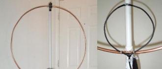
- the diameter of the large frame is 112 cm (a tube from an air conditioner or gas cylinder equipment of a car), it is very convenient and inexpensive to use a gymnastic aluminum hoop
- the diameter of the small frame is 22cm (the material is a copper wire with a diameter of 2 mm, it can be thinner, but the circle itself does not keep its shape)
- the RG58 cable connects directly to the small frame and goes to the radio receiver (you can use a 1 to 1 transformer to exclude reception on the cable)
- KPE 12 / 495x2 (any other can be used, the operating frequency band will just change)
- range 2.5 - 18.3 MHz
- so that the frame starts to accept 1.8 MHz, added a 2200 pF capacitor in parallel
The idea is not new. One of the options lies. This is a single turn frame. I got something like the following


The reception is excellent even on the 1st floor of a private house. I am amazed. This simple magnetic antenna (magnetic frame) is selective. Tuning for low frequencies is sharp, for high frequencies it is smoother. With a conventional KPE 12 / 495x2 with one section, the antenna is operational up to the 18 MHz range. With the connection of the second section, the lower limit is 2.5 MHz.
I was especially impressed with the work of the frame at 7 MHz. It turns out to be an excellent magnetic antenna for Degena.
finally video
What is not clear ask. de RN3KK
Added on 06/19/2014
Here we have moved to the new QTH 9th floor of a 9-storey building. On the standard telescope of the Sony TR-1000 receiver, significantly fewer stations are received than on the magnetic frame. + very narrow antenna bandwidth makes it an excellent preselector. Alas, there is no magic, when the neighbor downstairs turns on his plasma, the reception goes out everywhere ... even at 144 MHz ...
Added on 08/18/2014
There is no limit to surprise. I placed this antenna on the 9th floor loggia. A lot of Japanese stations were heard in the 40m range (the range to Japan is 7500 km). Only one Japanese station was received on 80m on the same day. The antenna deserves attention. I could not even think that this magnetic antenna (magnetic frame) could receive long-distance tracks ..
Added on 25.01.2015
The magnetic frame also works for transmission. No matter how strange it may seem, they answer. It does not work badly at 14 MHz, at the lower ranges the efficiency is not the same - you need to increase the diameter. Even at a power of 10 W, the brought up energy-saving lamp glowed at almost full power.
Reduced magnetic loop antennas are relatively rarely used by Ham-radio amateurs. However, with their disadvantages, such as low efficiency and narrow bandwidth, they have a number of their advantages. This is the possibility of spatial and frequency selection of the radio signal, i.e. antenna orientation according to the maximum of the useful signal or to the minimum of the interference signal. Isolation of the useful signal by the frequency detuning method, as well as its small geometric dimensions relative to the wavelength. Therefore, loop antennas are most widely used as receiving antennas for radio direction finders and broadcasting receivers operating in the ranges of long, medium and short waves.
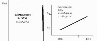
Such antennas are used most often in field conditions, and can be tuned in the range with a threefold change in frequency. Antenna efficiency depends on its geometric dimensions relative to the wavelength, see Fig. one.
This antenna is also used as a transmitting antenna. With small dimensions of the frame, the amplitude and phase of the oscillations of the current flowing in the frame are practically constant along the entire perimeter. The maximum radiation intensity corresponds to the plane of the frame. In the perpendicular plane of the frame, the radiation pattern has a sharp minimum, and the overall pattern of the loop antenna has the shape of a "figure eight".
Electric field strength E electromagnetic wave (V / m) at a distance d (?? 3) from transmitting loop antenna, calculated by the formula:
![]()
where:
I
- current in the frame (A); n
- number of turns; d
- distance (km);
S
- frame area (sq. M); ?
- working wavelength (m);
Cos?
- the angle between the plane of the frame and the direction to the point in question.
EMF E induced in foster loop antenna, calculated by the formula:
![]()
where:
n
- number of turns;
S
- the area of the frame;
E
- the strength of the electric field at the observed point;
Cos?
Is the angle between the plane of the frame and the direction of arrival of the wave.
The eight-dimensional radiation pattern of the frame allows you to use its minima of the pattern in order to detune it in space from closely located interference or unwanted radiation in a certain direction in the near zones up to 100 km.
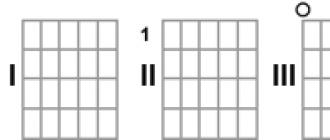
The antenna device is classical, and is shown in Fig. 2, it consists of an open oscillatory circuit in the form of a swept inductance tuned by a capacitor C into resonance. According to DK5CZ, the bandwidth also triples as the tuning frequency increases, and at 0.707 has a bandwidth of 3 to 30 kHz. When manufacturing the antenna, it is required to observe the ratio of the diameters of the radiating ring and the D / d communication loop as 5/1, it is made of a coaxial cable, is located in the immediate vicinity of the radiating ring on the opposite side of the capacitor, and looks like in Fig. 3.

Since a large current flows in the emitting frame, reaching tens of amperes, the frame in the frequency ranges 1.8-30 MHz is made of a copper tube with a diameter of about 40-20 mm, and the tuning capacitor into resonance should not have rubbing contacts. Its breakdown voltage should be 10 kV with a power input of up to 100 W. The diameter of the radiating element depends on the range of frequencies used and is calculated from the wavelength of the high-frequency part of the λw range, where the perimeter of the frame is P = 0.25λw.
We expand the bandwidth of the frame and increase the efficiency
The only problem that arises with all shortened loop antennas is narrowband. In the range of 180-160 m with an antenna quality factor of 200 ... 250, the bandwidth at the level of 0.707 will be about 6 kHz, which is a big disadvantage when tuning the frequency of the radio station. Tuning the antenna within the range can be done discretely, using a relay and a set of fixed capacitors.
To expand the bandwidth of the loop antenna and increase the efficiency of its operation, you can use several similar antennas, which are located in such a way relative to each other so that there is a magnetic connection between them. This means that the frames must be parallel to each other. In this case, it is enough to power only one antenna, and the rest will expand the bandwidth of the entire system, and increase the signal level by about 3 dB. In fig. 4a shows the frequency response of a single loop antenna, Fig. 4b - frequency response of two (or several) such antennas.

The frames must have the same geometric and electrical parameters and are installed parallel to each other at a distance of no more than the diameter of the frame. The distance is determined by the required bandwidth without sacrificing boost gain. The communication loop is installed on any of the frames, so that the second one works independently. A loop antenna works even better if three are installed, i.e. one in the middle, and two additional ones are placed at a distance of half the diameter of the frame on both sides in the same plane.
If the radio amateur has difficulty in rotating such a design, then the goniometer principle can be used and the frames can be placed perpendicularly. Then only the communication loop needs to be rotated. It will almost turn out to be a direction finder.
73! UA9LBG & Radio-Vector-Tyumen
This publication is intended for beginners.
radio amateurs and for those who do not have access
on the roof of your house. Sushko S.A. (ex. UA9LBG)
ML type Magnetic Loop antennas are becoming more and more popular due to their small size. All of them can be placed on balconies and window sills. It is undeniable that the classic popularity was gained by single-turn magnetic antennas with a vacuum capacitor and a communication loop, with the help of which it is possible to conduct radio communications even with other continents.
Two-loop antennas in the form of a figure eight began to appear relatively recently among radio amateurs, although at the dawn of the emergence of CBC communications in Russia, such antennas were practiced with some success in automobile radio security systems in the 27 MHz range, see Figure 1.a. The car antenna consisted of two identical frames (loops) L1; L2 and a common resonant capacitor C1, standing at the voltage antinode. With an antenna perimeter of about 5 meters, radio amateur Sterlikov A. ( RA9SUS) made connections with 36 countries with a power of up to 30 watts. The antenna was powered directly from the coaxial cable. And such antennas have been practiced since the late 60s, early 70s of the last century. The equivalent circuit of such an antenna is shown in Fig. 1.b.
Although single-turnMLare currently widely used among radio amateurs, a feature of the two-orbit is that its aperture is twice as large as compared to the classical one. The capacitor C1 can change the resonance of the antenna with frequency overlap by 2-3 times, and the total perimeter of the circumference of the two loops is ≤ 0.5λ. This is comparable to a half-wave antenna, and its small radiation aperture is compensated by an increased Q factor. It is better to match the feeder with such an antenna by means of inductive or capacitive coupling.
Theoretical digression: A double loop can be viewed as a mixed oscillatory systemLL andLC systems. Here, for normal operation, both arms are loaded on the radiation medium synchronously and in phase. If a positive half-wave is fed to the left shoulder, then exactly the same wave is fed to the right shoulder. The EMF of self-induction generated in each arm will, according to Lenz's rule, be opposite to the EMF of induction, but since the EMF of induction of each arm is opposite in direction, the EMF of self-induction will always coincide with the direction of induction of the opposite arm. Then the induction in the L1 coil will be summed up with the self-induction from the L2 coil, and the induction of the L2 coil - with the L1 self-induction. As in the LC circuit, the total radiation power can be several times higher than the input power. Power can be supplied to any of the inductors and in any way.
Converting the antenna from a rectangular shape to a round one (Fig. 1.a), we get the antenna shown in Fig. 2.a. It is fairly believed that the circular shape of the magnetic antenna is more efficient than the rectangular one.
Gradually, the constructive structure of the L1 and L2 frames was simplified, they began to be included in the form of an eight, in Figures 2.a. and 2.b. This is how a figure-eight two-frame ML appeared. Let's call it conditionally ML-8.
The ML-8, in contrast to ML, has its own peculiarity - it can have two resonances, the oscillatory circuit L1; C1 has its own resonant frequency, and L2; C1 has its own. The task of the designer is to achieve the unity of resonances and the maximum efficiency of the antenna, therefore, the manufacture of loops L1 and L2 should be the same. In practice, an instrumental error of a few centimeters changes one or another inductance, the tuning frequencies of the resonances diverge, and the antenna receives a certain frequency delta. Sometimes the constructor does this on purpose. This is especially convenient for multi-turn loops. In practice, ML-8 makes extensive use of LZ1AQ; K8NDS et al. Unequivocally arguing that such an antenna works much better than a single-loop antenna, and changing its position in space can be easily controlled by spatial selection, which is confirmed by the photo below in the text of the antenna at 145 MHz.
Preliminary calculations show that for the ML-8 for a range of 40 meters, the diameter of each loop at maximum efficiency will be slightly less than 3 meters. It is clear that such an antenna can only be installed outdoors. And we dream of an effective ML-8 antenna for a balcony or even a windowsill. Of course, you can reduce the diameter of each loop to 1 meter and tune the resonance of the antenna with the capacitor C1 to the required frequency, but the efficiency of such an antenna will drop by more than 5 times. You can go the other way, save the calculated inductance of the loop, using not one, but two turns in it, leaving the resonant capacitor with the same rating. There is no doubt that the antenna aperture will decrease, but the number of turns "N" will partially offset this loss, according to the formula below:
From the above formula, it can be seen that the number of turns N is one of the multipliers of the numerator and is in the same row, both with the area of the turn-S and with its quality factor-Q.
For example, a radio amateur OK2ER(see Fig. 3) considered it possible to use a 4-turn ML with a diameter of only 0.8 m in the range of 160-40 m.
The author of the antenna reports that the antenna works nominally at 160 meters and is used more for radio surveillance. In the range of 40m. it is enough to use a jumper that halves the working number of turns. Let's pay attention to the materials used - the copper pipe of the loop is taken from water heating, the clips connecting them into a common monolith are used to install water-supply plastic pipes, and a sealed plastic box was purchased at an electrician's store. The matching of the antenna with the feeder is capacitive, and probably according to one of the presented schemes, see Fig. 4.
In addition to the above, we need to understand what negatively affects the Q-factor of the antenna as a whole:
From the above formula, we see that the active resistance of the inductance Rk and the capacitance of the oscillatory system CK should be minimal. It is for this reason that all MLs are made of copper pipes, the largest possible diameter, but there are cases when the loop sheet is made of aluminum, and the quality factor of such an antenna and its efficiency drops from 1.1 to 1.4 times.
With regard to the capacity of the oscillatory system, then everything is more complicated. With a constant loop size L, for example, at a resonant frequency of 14 MHz, the capacitance C will be only 28 pF, and the efficiency = 79%. At a frequency of 7 MHz, efficiency = 25%. Whereas at a frequency of 3.5 MHz with a capacitance of 610 pF, its efficiency = 3%. Therefore, ML is used most often for two ranges, and the third (lowest) is considered simply an overview. Therefore, when calculating, we will "dance from the stove", i.e. from the highest range selected by the radio amateur with a minimum capacity C1.
Directional pattern ML-8 remains exactly the same as in the ML variant. For both antenna options, the eight-beam radiation pattern and the corresponding polarization are fully preserved. In the photo, using a gas-discharge lamp, the radiation levels of the antenna from different sides are clearly shown.
We design an antenna for a range of 20m.
Now armed with some basic knowledge of ML-8 design, let's try to manually calculate our antenna.
The wavelength for a frequency of 14.5 MHz is (300 / 14.5) - 20, 68 m.
The circumference of each quarter-wave loop is L1; L2 will be 5.17m. Let's take -5m.
The frame diameter will be: 5 / 3.14 - 1.6m.
Conclusion: A single ML hinge may fit into a balcony interior, but ML-8 is unlikely ...
Let's roll each loop in half, but its diameter, while maintaining the given inductance (4 μH), will slightly differ in the smaller direction. Let's resort to a fairly popular radio amateur calculator and determine the geometric dimensions of a two-turn loop with the same inductance.
In accordance with the calculations, the parameters of each loop will be as follows: When the diameter of the sheet (copper pipe) is 22mm, the diameter of the double loop will be 0.7m, the distance between the turns is -0.21m, the inductance of the loop will be 4.01mkH. The required design parameters of the loop for other frequencies are summarized in Table 1.
Table 1.
|
Tuning frequency (MHz) |
Capacitance C1 (pF) |
Bandwidth (kHz) |
|
Note: The ML-8 antenna has not only extended bandwidth, but also increased gain.
In height, such an antenna will be only 1.50-1.60 m. That is quite acceptable for an antenna of the type - ML-8 balcony version and even an antenna hung outside the window of a residential multi-storey building. And its wiring diagram will look like in fig. 6.a.
Antenna power can be capacitively coupled or inductively coupled. Capacitive coupling options are shown in Fig. 4 and can be selected at the request of the radio amateur.
The most budgetary option is inductive coupling. It is not worth repeating in the schematic representation of the communication loop, it is completely identical to that of ML-type antennas, except for the calculation of its perimeter.
Calculation of the diameter (d) of the tie loop ML-8 is made from the calculated diameter of two loops.
The circumference of the two loops after recalculation is 4.4 * 2 = 8.8 meters.
Let's calculate the imaginary diameter of two loops D = 8.8m / 3.14 = 2.8 meters.
Let's calculate the diameter of the connection loop - d = D / 5. = 2.8 / 5 = 0.56 meters.
Since in this design we use a two-turn system, the communication loop must also have two loops. We twist it in half and we get a two-turn communication loop with a diameter of about 28 cm. The selection of communication with the antenna is carried out at the time of the SWR specification in the priority frequency range. The coupling loop can be galvanically coupled to the zero voltage point (Fig. 6.a.) and be located closer to it.
Antenna adjustment and display elements
1. For tuning into resonance of a magnetic antenna, it is best to use vacuum capacitors with high breakdown voltage and high quality factor. Moreover, using a gearbox and an electric drive, its adjustment can be carried out remotely.
We are designing a budget balcony antenna that you can approach at any time, change its position in space, rebuild or switch to a different frequency. If at points "a" and "b" (see Fig. 6.a.) Instead of a scarce and expensive variable capacitor with large gaps, you connect a capacitor made of RG-213 cable sections with a linear capacity of 100 pF / m, then you can instantly change the frequency settings, and adjust the tuning resonance with the tuning capacitor C1. The condenser cable can be rolled up and sealed in any of the ways. Such a set of capacities can be had for each range separately, and can be connected to the circuit by means of a conventional electrical outlet paired with an electrical plug. Approximate capacities C1 by ranges are shown in table1.
2. It is better to indicate the tuning of the antenna to resonance directly on the antenna itself (this is clearer). To do this, it is enough not far from the communication coil on canvas 1 (point of zero voltage) to wind tightly 25-30 turns of MGTF wire, and seal the setting indicator with all its elements from precipitation. The simplest diagram is shown in Fig. 7.
Electric emitter, this is another additional element of radiation. If the magnetic antenna emits an electromagnetic wave with the priority of the magnetic field, then the electric emitter will perform the function of an additional emitter of the electric field-E. In fact, it should replace the initial capacitance C1, and the drain current, which previously was uselessly passed between the closed plates of C1, now operates on additional radiation. Now a fraction of the supplied power will be additionally emitted by electric emitters, Fig. 6.b. The bandwidth will increase to the limits of the amateur radio band as in the EH antennas. The capacity of such emitters is low (12-16pF, no more than 20), and therefore their efficiency in low-frequency ranges will be low. You can familiarize yourself with the operation of the EH antennas by following the links:
Antenna type ML-8 radio observer greatly simplifies the design as a whole. As the material of the loops L1; L2, you can use cheaper materials, for example, a PVC pipe with an aluminum layer inside for laying a water pipe with a diameter of 10-12 mm. Instead of high-voltage capacitors, ordinary capacitors can be used, with a small TKE, and for smooth tuning to the frequency, use double varicaps with control from the place of radio observation.
Conclusion
All mini-antennas, whatever they may be, in relation to simple tension and classic antennas require a lot of labor and locksmith skills. But the lack of the ability to install outdoor antennas, radio amateurs are forced to use both EH and ML antennas. The design of the two-turn Magnetic Loop is convenient in that all adjustment, coordination and indication elements can be placed in one sealed case. The antenna itself can always be hidden from fastidious neighbors in one of the available ways, a great example in the photo below.