Radio antennas help to significantly improve sound quality, avoid interference, the original radio antenna can become an interesting element of the interior. Recently, magnetic-based designs have begun to appear and are in demand among radio amateurs. The magnetic loop antenna can be successfully replaced by outdoor devices for receiving radio signals in the range from 10 to 80 meters by using frames. They can be built anywhere in the city, as well as in a car, as an alternative to screwing to the body. Such antennas are very convenient and mobile, however, with a rather simple design, their use has some peculiarities.
Magnetic loop antenna device
Conventional antennas, in addition to the fact that they are fastened firmly enough, must have a very decent mass, which is simply impossible to bring to mobile lightweight radio reception devices. In modern conditions, a way has been found - the required mass is simply imitated. This is done using a coaxial coaxial cable, which, with a length of half a radio wave taken with a shortening factor, acts as an impedance amplifier.
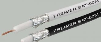
The central conductive core (or several) of such a cable is made of pure or tinned copper, which provides increased resistance to direct current, and also makes the cable flexible. The dielectric layer is made of expanded polyethylene granules. These materials give the stability of the quality characteristics of the wire and a long service life. The shielding layer is a braid of copper or tinned wires. To increase the shielding properties, a second layer of braid is made over the laminated aluminum foil.
Modern magnetic antennas are improved variations of loop analogs. Such devices are coils with ferrite cores. Due to the increased magnetic permeability of this material, the magnetic field of electromagnetic waves in the coil circuits generates a very powerful flux, stronger than with the missing core.

Even small coils are capable of creating the same electromotive force as simple frame antennas, but of large dimensions.
The dimensions of the cores are from 0.1 to 0.3 meters in length and from ½ to 1 square meter. see cross-sectional area. Each coil, as a rule, has 2-3 tens of turns of copper wire.
Coaxial antenna magnetic frames are loops of conductive material attached to a capacitor. Most often, there are round loops, since this way the device works much more efficiently. The area of the circle is smaller than the area of other geometric shapes, so the radio coverage will be higher.
Note! In stores for radio amateurs, antenna frames are sold precisely in a round shape. However, there are triangular, and square, and even polygonal frames, their use is explained by the peculiarities of the location in the house, the dimensions of the radio receiver, etc.

To receive a signal in the selected range, loops of different diameters are used.
Within the framework of both round and square shapes, an untwisted conductor is used (such antennas are called single-turn), they function perfectly at high frequency ranges, but at the same time their dimensions are quite large. These shortcomings are corrected by the multi-turn magnetic frame design, which is gaining popularity among radio amateurs who prefer low frequencies.
Additional Information. The more turns, the smaller the dimensions of the antenna device.
Features of operation and location of the device
A magnetic loop antenna made of coaxial cable is used mainly in cases where it is necessary to reduce the level of interference and noise from neighboring radio stations operating in a range close to the waves of the receiving device, but emitted in the other direction. Loop antennas are best at receiving radio waves propagated along its plane, but they do not catch signals going in parallel at all. In order to achieve the best, without interfering with the sound of the desired radio station, you just need to rotate the frame around its axis.
Such mechanisms can also be located on the roof of a building. However, it should be borne in mind that such antennas must be higher than others (therefore, with a balcony installation, the efficiency decreases). At the same time, the operation of magnetic loop antenna devices is not affected by the proximity to other objects and structures (ventilation towers, pipes, etc.).
It is almost impossible to achieve an ideal location, however, it would be best to install the antenna so that the ferrite core is directed into the distance, in which case the radio signal will not be suppressed by antennas with larger dimensions.
For normal operation of a loop antenna with a coaxial cable, it is necessary to synchronize the wire itself and the frames. Consistency can be achieved by placing small induction loops in larger diameters. In order for the structure to work symmetrically, a balancing transformer device can be added to it. If the symmetry of the radio is not required, the cable to the antenna can be connected directly.
![]()
For the antenna, it is necessary to provide grounding, it is made in the area where the loop is attached to the point where the base of the large loop is located.
Important! If the cable is slightly deformed, the antenna can be tuned more finely.
It is not recommended to shorten the coaxial cable during installation and further operation, therefore it is advisable to determine before purchasing the antenna what length will be sufficient.
It seems simple to install a magnetic loop antenna in a car, but this manipulation must be done very carefully. Before placing the magnetic antenna on the body, it is necessary to clean the future installation site and magnetic cushion of the antenna from clogging, otherwise the car paintwork may be damaged.
Pros and cons of the device
Magnetic antennas made of coaxial cable have many advantages over other devices for a similar purpose:
- they are relatively easy to install, and in the future they do not require special maintenance during operation;
- can be installed in small spaces;
- the service life of such antennas is quite long;
- availability and low cost of components, it can be assembled independently with initial knowledge and experience in radio engineering;
- can function normally, being in the vicinity of other radio units, the use of a magnet as a component provides excellent clear reception in urban conditions;
- stability of work does not depend on seasonal and weather conditions, no special efforts are required to achieve clear reception of the radio signal;
- car antennas on a magnetic base are very mobile, i.e. they can be installed in a few minutes and anywhere in the car (no drilling is required), which can add a noticeable touch to the exterior of the car (besides, you can put several antennas: in different places, which will once again demonstrate the "coolness" of the car owner) ;
- since the gain of the radio signal drops sharply at wavelengths less than 1/10 of the length of the perimeter, the receiving magnetic antenna helps protect the radio receiver from being overloaded by other radio stations;
- In the VHF-FM range (frequency modulation, i.e. at frequencies of 65.9-74 megahertz), magnetic antennas demonstrate the highest quality reception compared to analogs or even outdoor devices, while the size of the frame perimeter is from 20 to 40 centimeters ...
Magnetic antennas with coaxial cable are not without some disadvantages:
- if you have to change the operating range of the radio receiver, you need to constantly adjust the variable capacitors for clearer signal reception;
- the easiest way to get rid of interference and extraneous ether noise is by turning the antenna structure around its own axis and at the same time changing its location, however, for frame magnetic devices such manipulations are difficult due to the different shape of the frames and the inconvenient location of the wooden loop;
- during signal transmission, metal structural elements become very hot, which is fraught with burns if handled carelessly;
- after installation, the length of the coaxial cable cannot be changed, because the reception may deteriorate significantly, which is explained by a failure of the parameters in the oscillatory system of the radio receiver;
- on a round or square frame there is an input electrical resistance of 120 ohms, while on a feeder it is 50 ohms, therefore, for matching, you have to form a frame in the shape of a rectangle, where the short sides are half the long ones, then the resistance at the input will also be 50 ohms, however, constructively it is rather difficult and inconvenient;
- the more the real mass of the magnetic antenna is replaced by the coaxial wire, the lower the reception quality, therefore antennas of this type must be chosen very thoughtfully.
DIY antenna assembly
Magnetic loop antennas have a fairly simple design, so they can be performed even by inexperienced radio amateurs. This antenna can be assembled using any size coaxial cable.

To create the simplest instance of a magnetic antenna, the following constituent elements are required:
- coaxial cable (coaxial) brand RG213, about 12 meters;
- cable brand RG58, about 4 meters;
- strips of dry wood, 2 by 4 cm in the amount of 4 pieces;
- capacitor with a capacity of 100 picofarads, 1 piece, while the plate-to-plate distance should not exceed 3 mm;
- coaxial connector, one piece.
Mounting parts of a homemade loop magnetic antenna is a fairly simple procedure. First, a cross is built from wooden slats, planks with sawn grooves are attached to it in the transverse direction. A loop is mounted on the cross to create resonance. It should consist of at least 4 turns of RG213 wire.
In addition, two holes are drilled in the crossbars located on the top, left and right, where the ends of the cable will be securely fixed. Three grooves must be cut between them. The dimensions of the cross base are not so important, but the side of the coaxial should be exactly 67 centimeters.
The frame should have the sum of the side lengths equal to 1/10 of the wavelength of the lower fm band or the required shortwave frequency. However, if the radio signal is strong enough, then a perimeter equal to 1/10 of the wavelength of the upper FM channel is acceptable.
If such a homemade antenna is planned to be used for a long period (both in open areas and indoors), it is best to take a cable made of technical copper with a foil braid (sometimes a tube polished to a shine is also suitable). Otherwise, good radio reception cannot be expected over time.
For painting, it is best to use paints containing metal oxides.
As for the magnetic frame, for the most effective functioning of the structure, it is necessary that the losses in its canvas be adequate to the resistance of the entire system.
Coaxial Magnetic Loop Antennas are a modern enhancement to conventional loop antennas that provide excellent RF reception mainly in the FM band and offer increased mobility. A completely working copy can be assembled independently without even going through special training.
Video
The magnetic loop indoor antenna is a great alternative to the classic outdoor antenna. Such designs allow transmitting signals up to 80 m. Coaxial cable is most often used for their manufacture.
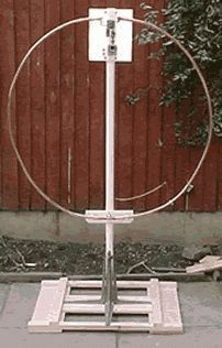
Classic version of the magnetic loop antenna
A frame magnetic installation is a subtype of small-sized amateur antennas that can be installed anywhere in a settlement. Under the same conditions, the frames show a more stable result than analogs.
In home practice, the most successful models of popular manufacturers are used. Most of the circuits are found in the amateur radio engineering literature.

Indoor coaxial magnetic loop antenna
DIY antenna assembly
Materials for making
The main element is several types of coaxial cable, 12 m and 4 m long. To build a working model, you also need wooden slats, a 100 pF capacitor and a coaxial connector.
Assembly
A magnetic loop antenna is constructed without special training and knowledge of technical literature. By adhering to the assembly order, you can get a working device the first time:
- connect wooden planks with a cross;
- cut grooves in the planks, the depth corresponding to the radius of the conductor;
- drill holes on the strips at the base of the cross to secure the cable. Cut three grooves between them.
Accurate dimensional control allows you to build a structure with high radio frequency reception.
Magnetic frame shape
A coaxial magnetic antenna is a loop of conductor that connects to a capacitor. The loop is usually circular. This is because this shape increases the efficiency of the structure. The area of this figure is the largest in comparison with the area of other geometric bodies, therefore, the signal coverage will be increased. Manufacturers of goods for radio amateurs produce precisely round frames.

Installation of the structure on the balcony
In order for the devices to work at a specific wavelength range, loops of various diameters are constructed.
There are also models in the form of triangles, squares and polygons. The use of such structures is due in each case to different factors: the location of the device in the room, compactness, etc.
Round and square frames are considered single-turn, because the conductor is not twisted. Today, special programs such as KI6GD allow calculating the characteristics of single-turn antennas only. This type has proven itself well for high-frequency operation. Their main disadvantage is their large size. Many professionals tend to work at low frequencies, which is why the magnetic loop installation is so popular.
Comparative calculations of several circuits with one, two or more turns, under similar operating conditions, showed the dubious efficiency of multi-turn structures. The increase in turns is most advisable only to reduce the size of the entire device. In addition, to implement this scheme, an increase in cable consumption is necessary, therefore, the cost of homemade products unjustifiably increases.
Magnetic frame canvas
For maximum efficiency of the installation, one condition must be achieved: the resistance of losses in the frame fabric must be comparable to the value of the radiation resistance of the entire structure. For thin copper tubes, this condition is easily met. For coaxial cables of large diameter, this effect is more difficult to achieve due to the high resistance of the material. In practice, both types of structures are used, since other types work much worse.
Receiving frames
If the device performs exclusively the function of a receiver, then ordinary capacitors with solid dielectrics can be used for its operation. To reduce dimensions, the receiving frames are multi-turn (made of thin wire).
Such designs are not suitable for transmitting devices, since the action of the transmitter will work to heat the installation.
Coaxial cable braid
The braiding of the magnetic frame provides greater efficiency than copper tubes and thickening of the conductor diameter. Models in a black plastic shell are not suitable for home experiments, because it contains a large amount of soot. During operation, metal parts, with strong heating of the shell, emit chemical compounds harmful to humans. In addition, this feature reduces the transmission signal.

Coaxial cable SAT-50M made in Italy
This type of coaxial cable is only suitable for large antennas because their radiation resistance of the conductor fully compensates for the input resistance.
Impact of external factors
Due to the physical properties of coaxial cables, antennas are not affected by temperature and precipitation. Only the shell created by external factors - rain, snow, ice, lends itself to negative consequences. water has large losses at high frequencies in comparison with cable. As practice shows, it is possible to use such structures on balconies for several decades. Even in severe frosts, there is no significant deterioration in reception.
To increase the reception, magnetic devices from a coaxial cable are best placed in rooms or places with reduced exposure to precipitation: under the canopies, on the protected parts of open balconies. Otherwise, the device will work primarily to heat the environment, and only then to receive and transmit signals.
The main condition for stable operation is the protection of the capacitor from external influences - mechanical, weather, etc. With prolonged exposure to external factors due to high-frequency voltage, an arc may form, which, if overheated, quickly leads to a taps from the circuit or failure of this part.
The frames for high-frequency ranges are horizontal. For low-frequency ones, with a height of more than 30 m, it is advisable to build vertical structures. For them, the installation height does not affect the reception quality.
Device location
If this mechanism is located on the roof, then one condition must be provided - this antenna must be higher than all the others. In practice, perfect placement is often not possible. The magnetic frame installation is rather unpretentious to the close location of third-party objects and structures - ventilation towers, etc.
It will be correct to place the core on the roof far away so that there is no signal absorption by large models. In view of this, when installed on a balcony, its efficiency decreases. This arrangement is justified in cases where conventional receivers do not work correctly.
Synchronization of frame and cable
Matching of parts is achieved by placing a small inductive loop into a large one. For balanced communication, a special balancing transformer is included in the device. For unbalanced, connect the cable directly. The antenna is grounded at the point where the loop is attached to the base of the large circle. The deformation of the loop helps to achieve a more accurate adjustment of the device.

Modification of a device from a coaxial cable
Pros and cons of the device
Advantages
- low cost;
- ease of installation and maintenance;
- availability of raw materials;
- installation in small rooms;
- durability of the device;
- effective work near other radio devices;
- lack of special requirements to achieve high-quality reception (such devices work stably both in summer and in winter).
Flaws
The main disadvantage is the constant tuning of the capacitors during the change of the operating range. The level of interference is reduced by turning the structure, which is extremely difficult during operation due to the geometric shapes and location of the wooden planks. Due to radiation at a close distance, information is transmitted from magnetic tapes (when the tape recorder is turned on) to devices with inductors (TVs, radios, etc.) even when the antennas are turned off. The level of interference can be reduced by changing the position of the device.
During operation, do not touch metal parts, due to strong heating you can get burns.
We do it ourselves. Video
How to make a broadband active antenna with your own hands, you can learn from this video.
The magnetic loop antenna is the most reasonable budget solution for home use. The main advantages are operation at different frequencies, ease of assembly and compactness. A well-made device can receive and transmit an excellent signal over a fairly long distance.
At the mention of a magnetic antenna, those on the ferrite rod somehow immediately come to mind, and this is partly correct. These are all varieties of the same type of device. A loop antenna is called a magnetic antenna, the perimeter of which is much less than the wavelength. The well-known zigzag and biquadrat (almost the same thing) are also related to the technology in question. And antennas on a magnetic base have nothing to do with them. It's just a way of attaching nothing more. The magnetic antenna base holds it securely on the roof of any car. We're talking today about a special design. The beauty of magnetic antennas is that they can provide relatively high gain at relatively long wavelengths. Moreover, the size of the magnetic antenna is quite small. Let's discuss our title and tell you how a do-it-yourself magnetic antenna can be made.
Magnetic antennas
It is known from theory that almost no radiation occurs in the oscillatory circuit from the inductor and the capacitor. It is all closed, and the wave can swing at the resonant frequency for an arbitrarily long time, damping due to the presence of active resistance. Yes, circuit elements, inductance and capacitance, in general, have a purely reactive (imaginary) impedance. Moreover, the size depends on the frequency according to a fairly straightforward law. This is something like the product of the angular frequency (2 P f) by the value of inductance or capacitance, respectively. And now, at a certain value, the imaginary components of opposite sign become equal. As a result, the impedance becomes purely active, ideally zero.
In reality, the beats are still damped, because in practice each circuit is characterized by a Q factor. Recall that impedance consists of a purely active (real) part, such as resistors, and an imaginary part. The latter include capacitance, the resistance of which is imaginary negative and inductance with a positive imaginary resistance. Now imagine that in the circuit, the plates of the capacitor began to be wired until they were at opposite ends of the inductance. This is called a Hertzian vibrator (dipole), and is a type of shortened half-wave and other types of vibrators.
If we take and turn the coil into a single ring, then we get the simplest magnetic antenna. This is a very simplistic interpretation, but roughly the way it is. Moreover, the signal is removed from the side opposite to the capacitor through an amplifier on field-effect transistors. This ensures high sensitivity of the device. Well, an antenna on a ferrite rod is a kind of magnetic, only it has a lot of rings instead of one. This type of device got its name for its high sensitivity to the magnetic component of the wave. In particular, when working on a transmission, it is just it that is generated, generating the response of an electric field.
The maximum directivity corresponds to the axis of the rod. Moreover, both directions are equal. Due to the small perimeter of the loop antenna relative to the wavelength, its resistance is quite low. It can be not just 1 Ohm, but even a fraction of Ohm. The approximate value can be estimated by the formula:
R = 197 (U / λ) 4 Ohm.
U means the perimeter in meters, in the same units as the wavelength λ. Finally, R is the resistance to radiation, it should not be confused with the active one, which is shown by the tester. This parameter is used when calculating an amplifier for load matching. Therefore, for ferrite antennas, you need to multiply this value by the square of the number of turns.
Properties of magnetic antennas
Now let's see how to make a magnetic antenna yourself. First you need to determine the circumference and capacity of the trimmer capacitor. In fact, the features of a magnetic antenna are such that it requires approval without fail, but more on that some other time. The fact is that the hallmark is an incredible number of options for carrying out this operation, so a separate topic for conversation looms.

The length of the perimeter of the magnetic antenna ranges from 0.123 to 0.246 λ. If you want to cover this entire range, then you need to choose the right capacitor. In free space and in a magnetic antenna, the radiation pattern is in the form of a torus, which can be observed by placing the coil parallel to the ground. In this case, the polarization will be linear horizontal. That is, it is an excellent option for receiving television broadcasting. The disadvantage is that the angle of elevation of the petal depends on the height of the suspension. It is believed that for the distance λ to the Earth it will be 14 degrees. And this impermanence is a negative quality. But for radio, magnetic antennas are used quite often.
The gain is 1.76 dBi, 0.39 less than the half-wave vibrator. But the size of the latter for this frequency will be tens of meters - well, where do you go to such a whopper? Draw your own conclusions. Our magnetic antenna is not that big (the perimeter can be 2 meters for a wavelength of 20 meters, which is less than a meter across). For comparison, at 34 MHz, which truckers are familiar with, thanks to walkie-talkies, the wavelength is 8.8 meters. At the same time, everyone knows that not every Kamaz can accommodate a good half-wave vibrator. And, by the way, we have already given a description of the design of the loop antenna formed by the rubber gasket of the rear window of a VAZ passenger car. For all its small dimensions, the device worked well enough.
By the way, this design is considered more pragmatic than typical whip antennas for cars, where tuning is carried out by changing the inductance. There are fewer losses. In addition, the radiation pattern covers fairly high elevation angles, almost to the vertical. This is not possible with a whip antenna.
But how to choose the right circumference? With its increase, the gain grows. That is, it must satisfy the condition given above and be as large as possible. In this case, do not forget that sometimes you need to cover several frequencies. In addition, as the perimeter grows, the bandwidth of the device increases. I must say, with a typical channel width of 10 kHz, this is not so important. In addition, neighboring carriers of broadcasting stations will be automatically cut off. In this sense, more does not necessarily mean better. Do not forget, however, that all the fuss was started for the sake of strengthening. Thus, the antenna is selected along the maximum perimeter with the required selectivity.
Now the main question is: how to determine the capacity? So that, together with the inductance of the loop, they form a resonance according to the well-known formula. As for determining the parameters of the contour, the following formula is given for it:
L = 2U (ln (U / d) - 1.07) nH;
where U and d are the length of the loop and its diameter. What's the catch here? U = П d, therefore, instead of their ratio, one could take the natural logarithm of the number Pi. Whether this is the author's mistake, we cannot say. Perhaps the fact is taken into account that the tuning capacitor takes away part of the length, as well as the amplifier ... We find the capacitance by the known inductance from the expression for the resonance of the circuit:
f = 1 / 2P √LC; where
С = 1 / 4П 2 L f 2.
The ring is the most effective and widespread design of a loop antenna, since, compared to other geometric shapes, it covers the largest area with equal perimeters. An octagon is very close to a ring in terms of efficiency, while a square or a rhombus has a lower efficiency.
Typically, a variable trimmer capacitor is placed at the top of a vertically mounted ring, which is grounded at the lower opposite point for lightning protection.
For the sake of convenience of settings, in some versions of the antenna, the capacitor is mounted at the bottom of the ring and often in the case together with the matching device.
Remote control of the variable trimmer capacitor is not difficult to carry out, and therefore, in stationary ring antennas, trimmer capacitors are placed in the upper part of the ring. They also easily cope with galvanic communication.
One of the solutions is shown in the figure above in the form of a T-match followed by a balun transformer.
The asymmetric version with gamma matching looks like:

In both cases, the length of the segment L, in gamma matching, should be about 0.1 of the circumference of the ring, and the distance y should be about λ / 200.
Inductive coupling and termination are also widespread due to their ease of implementation.
The most commonly used option is this type:

Inside the large loop, place a small inductive loop with a diameter ratio of 5: 1. Thanks to the balanced coupling via a 1: 1 ring-core balun, a 50-ohm coaxial cable can be connected.
In unbalanced communication, the coaxial cable is connected directly as in the figure above (b).
An electrically feasible inductive coupling method is shown in Figure (c). Shown here is only a tie loop of a broken coaxial cable.
his screen in the middle of the loop. The shield of the part of the right half of the loop is soldered to the base of the large ring, and at this point the antenna is grounded. Slightly deforming the cable from the coaxial cable, they achieve fine tuning of the antenna to the minimum SWR. It is believed that the diameter d should be the smaller, the higher the operating Q-factor of the antenna.
Experiments with magnetic loop antennas
Alexander Grachev UA6AGW
Last year I got my hands on a 6-meter piece of coaxial cable. Egative name: "Coaxial cable 1" flexible LCFS 114-50 JA, RFS (15239211) ". It has a very light weight, instead of an outer braid, a solid corrugated pipe made of oxygen-free copper with a diameter of about 25 mm, the central conductor is a copper tube
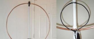
with a diameter of about 9 mm (see photo). This prompted me to start building a loop antenna. This is what I want to tell you about.
The first antenna was built according to the DF9IV scheme. With a diameter of about 2 m and the same length of a power loop made of a coaxial cable, it worked very well for reception, but frankly badly for transmission, SWR reached 5-6.
The working bandwidth for receiving (at the level of –6 dB) is about 10 kHz. At the same time, it perfectly suppressed electrical noise, with a certain orientation in space, the suppression of the interfering station easily turned out to be more than 20 dB.
After some thought, I came to the conclusion that the reason for the high VSWR is the use of an inner conductor with a relatively small diameter of the exciting element. It was decided not to use the inner conductor at all, leaving it in the form of an open loop.
The tuning capacitor was soldered to the outer shield. The receiving characteristics have changed insignificantly, the minimum in the diagram has become less pronounced, the influence of surrounding objects has become noticeable. But on the transfer, little has changed. Further, after reading Grigorov's article again, it was decided to remove the outer braid from the frame cable, and cover the copper in two layers with “XB” varnish (there was no more suitable one, however, it protects copper well from
oxidation). And then, finally, the first positive results appeared. VSWR dropped to 1.5, and about 20 local contacts were made. The antenna was at a height of 1.5 m and could rotate in a vertical plane.
For comparison, a dipole with a total length of 42.5 m was used, made of a field wire with a symmetrical power line from a telephone "noodle" about 20 m long (a kind of antenna of a "poor radio amateur"), located on the roof of a 5-storey building at a height of about 3 x meters. He worked on 40 and 80 meters, powered through a balanced matching device - SWR on both bands = 1.0. Unfortunately, the antennas were in different QTH and there was no
the ability to make direct comparisons. But the experience of operating the dipole during the year made it possible to judge the efficiency of the frame as a first approximation.
Now about the results: 1) SWR is about 1.5. 2) All correspondents noted a decrease (from 1 to 2 points) in the level of my signal, compared to that with which they usually hear me on a dipole.
The rains that had begun by this time (as they say: "every other day, every day") made further antenna experiments impossible. The main reason for the impossibility of further tests was the constant breakdowns of the tuning
condenser due to increased air humidity.
I tried, perhaps, all the options available to me, I used the connection of only stator plates, connecting two KPI in series, I used capacitors from a coaxial cable, high-voltage capacitors
- it all ended in one thing - a breakdown. I didn’t try only vacuum condensers, their prohibitive cost stopped them.
And here the idea came to use the capacitance in relation to the outer shield of the unused inner conductor. An attempt to calculate the required cable length based on the known linear capacity of the cable did not lead to reliable results, so the method of gradual approximation was used.

It was a pity to cut such a wonderful cable, but "hunting is worse than bondage." The connection diagram is shown in the figure. For power supply, a loop of a coaxial cable 2 m long was used, according to the DF9IV scheme, the supply 50-ohm cable itself was 15 m long. capacity of the cable.
For tuning, a butterfly-type capacitor from VHF equipment was used.
Breakdowns completely stopped, the antenna retained all the basic parameters of a classic magnetic loop antenna, but became single-band.
The main results are as follows: 1) VSWR of the order of 1.5 (depends on the length and shape of the feed loop). 2) The magnetic antenna noticeably loses to the dipole (described above) with a comparable suspension height. The experiments were carried out in a range of 80 m.
To engage in further experiments with magnetic antennas, I was prompted by the article by K. Rothammel in the second volume of his book, devoted to magnetic frames, and the article by Vladimir Timofeevich Polyakov on a frame-beam or real EH antenna, and for understanding the processes occurring in and around antennas, it turned out to be very a helpful article on near-field antennas.
After reading the article on the frame-beam antenna, I had several promising projects, but currently only one has been tested, and this will be the topic of discussion. The antenna diagram is shown in the figure, the appearance is in the photo:

All of the experiments listed below were carried out in a range of 40m. In the first experiments, the antenna was at a height of 1.5 m from the ground. Various ways of connecting the "dipole" (capacitive) part of the antenna to the frame have been tried, but the one shown in the figure seemed to me optimal. Here, an attempt has been made to equip a magnetic frame that emits a predominantly magnetic component with elements that emit mainly an electrical component.
You can look at the same antenna differently: the coil included in the middle of the dipole, as it were, lengthens it to the required dimensions, and at the same time, the rays connected in parallel with the tuning capacitor have their own capacitance (at the indicated dimensions of the order of 30-40 pF) and enter into the total capacity of the tuning capacitor.
The circuit formed by the inner conductor and the capacitor, in addition to increasing the signal level at the reception approximately twice, apparently shifts the phase of the current of the frame itself, and provides the necessary phase matching (an attempt to turn it off leads to an increase in SWR to 10 or more). Perhaps my theoretical reasoning is not entirely correct, but as further experiments have shown, the antenna works in this configuration.

Even during the very first experiments, an interesting effect was noticed - if, with a fixed dipole part, turn
a frame by 90 degrees - the signal level upon reception drops by approximately 10 - 15 dB, and by 180 degrees - the reception falls almost to zero. Although it would be logical to assume that when rotated 90 degrees, the directional patterns of the "dipole" part and the frame will coincide, but apparently not everything is so simple.
An intermediate version of the antenna was made, capable of turning around its axis, in order to find out the radiation pattern, it turned out to be the same as that of the classical frame. The antenna was powered by the same communication loop as in the first experiments. At present, the antenna is raised to a height of 3 meters, the rays are parallel to the ground.
About the results:
1) SWR = 1.0 at 7050 kHz, 1.5 at 7000 kHz, 1.1 at 7100 kHz.
2) The antenna does not require band tuning. With the help of the capacitors of the transceiver U-circuit, some tuning of the antenna is possible if necessary.
3) The antenna is very compact.
At a distance of up to 1000 km, the frame and the dipole have approximately the same efficiency, and at a distance of more than 1000 km, the frame works much better than the wave dipole with the same suspension height, while the frame is four times
less than a dipole. The directivity pattern is close to circular, minima are hardly noticeable. About a hundred contacts were made with 1; 2; 3; 4; 5; 6; 7; 9 regions of the former USSR.
An interesting effect was noted - the assessment of the signal strength in most cases remained approximately the same, and at a distance to the correspondent of 300 km and 3000 km, this was not observed on the dipole. The reaction of the operators is interesting,
when I said what I was working on, I was amazed that it was possible to work on it! All experiments were carried out on a homemade SDR transceiver with an output power of 100 watts.
Material taken from CQ-QRP magazine # 27