The modification of the well-known antenna proposed below will allow covering the entire short-wave radio amateur frequency range, slightly losing out to the half-wave dipole in the 160-meter range (0.5 dB on short paths and about 1 dB on long paths). If executed accurately, the antenna works immediately and does not need tuning. An interesting feature of the antenna is noted: it does not perceive static interference, compared to a band half-wave dipole, the reception is very comfortable. Weak DX stations are well listened to, especially on the low bands. Long-term operation of the antenna (almost 8 years at the time of publication, ed.) Made it possible to classify it as a low-noise receiving antenna. Otherwise, in my opinion, "in terms of efficiency, it is not inferior to a band half-wave antenna: a dipole or Inv. Vee on each band from 3.5 to 28 MHz. Another observation based on feedback from distant correspondents is that there are no deep QSBs during transmission. Of the 23 antenna modifications I have made, the one given here deserves the most attention and can be recommended for massive repetition. All dimensions of the antenna-feeder system are calculated and precisely verified in practice.
Antenna strip
The vibrator dimensions are shown in the figure above. Both halves of the vibrator are symmetrical, the extra length of the "inner corner" is cut in place, and a small insulated platform is also attached there to connect to the supply line. Ballast resistor 2400m, film (green), 10W. You can use any other of the same power, but always non-inductive. Insulated copper wire, cross-section 2.5mm. Spacers - lacquered wooden lath with a section of 1x1cm. Distance between holes 87cm. Stretch marks - nylon cord.
Overhead power line
Copper wire PV-1, 1mm cross-section, vinyl plastic spacers. The distance between the conductors is 7.5cm. The line is 11 meters long.
Author's installation option
A metal, bottom-grounded mast is used. Installed on the roof of a 5-storey building. The height of the mast is 8 meters, the pipe is 50mm in diameter. The ends of the antenna are located at a distance of 2 meters from the roof. The core of the matching transformer (SHPTR) is made from the TVS-90LTs5 line. The coils are removed, the core itself is glued together "supermoment" to a monolithic state and rolled with 3 layers of varnished cloth. Winding is carried out in two wires without twisting. The transformer contains 16 turns of 1mm diameter single-core insulated copper wire. Since the transformer has a square (or rectangular) shape, 4 pairs of turns are wound on each of the 4 sides - the best version of the current distribution. SWR over the entire range from 1.1 to 1.4. ShPTR is placed in a sheet metal screen, well soldered with a feeder braid. From the inside, the middle terminal of the transformer winding is reliably soldered to it. After assembly and installation, the antenna will work in almost any conditions: located low above the ground or above the roof of the house. A low level of TVI (television interference) was noted, which may be of interest to rural radio amateurs or summer residents.
 Yagi antennas with a loop vibrator located in the plane of the antenna are called LFA Yagi (Loop Feed Array Yagi) and are characterized by a wider operating frequency range than conventional Yagis. One of the popular Yagi LFAs is Justin Johnson's 5-piece construction (G3KSC) for the 6-meter range.
Antenna layout, distances between elements and dimensions of elements are shown in the table below and in the drawing.
The dimensions of the elements, the distances to the reflector and the diameters of the aluminum tubes from which the elements are made according to the table: The elements are installed on a traverse with a length of about 4.3 m from a square aluminum profile with a cross section of 90 × 30 mm through insulating transition strips. The vibrator is powered by a 50 ohm coaxial cable through a balun  1:1.
1:1. 
Antenna tuning for the minimum SWR in the middle of the range is performed by adjusting the position of the end U-shaped parts of the vibrator from tubes with a diameter of 10 mm. It is necessary to change the position of these inserts symmetrically, that is, if the right insert is pushed out by 1 cm, then the left one must be pushed out by the same amount.
The antenna has the following characteristics: maximum gain 10.41 dBi at 50.150 MHz, maximum front / rear ratio 32.79 dB, operating frequency range 50.0-50.7 MHz at SWR level = 1.1
"Prakticka elektronik"
SWR meter on strip lines
SWR meters, widely known from the amateur radio literature, are made using directional couplers and are single-layer  coil or ferrite ring core with multiple turns of wire. These devices have a number of disadvantages, the main of which is that when measuring high powers, a high-frequency "pickup" appears in the measuring circuit, which requires additional costs and efforts to screen the detector part of the SWR meter to reduce the measurement error, and with the formal attitude of the radio amateur to manufacturing instrument, the SWR meter can cause the impedance of the feed line to change depending on the frequency. The offered SWR meter based on strip-line directional couplers is free from such disadvantages, it is designed as a separate independent device and allows you to determine the ratio of direct and reflected waves in the antenna circuit with an input power of up to 200 W in a frequency range of 1 ... 50 MHz with a characteristic impedance of a feeder line 50 Ohm. If you only need an indicator of the transmitter output power or monitor the antenna current, you can use the following device: When measuring the SWR in lines with a characteristic impedance other than 50 Ohm, the values of the resistors R1 and R2 should be changed to the value of the characteristic impedance of the measured line.
SWR meter design
 The SWR meter is made on a 2 mm thick double-sided foil-clad PTFE board. As a replacement, it is possible to use double-sided fiberglass.
L2 line is made on the back side of the board and is shown with a dashed line. Its dimensions are 11 × 70 mm. Caps are inserted into the holes of line L2 for connectors XS1 and XS2, which are flared and soldered together with L2. The common bus on both sides of the board has the same configuration and is shaded in the board diagram. In the corners of the board, holes are drilled into which pieces of wire with a diameter of 2 mm are inserted, soldered on both sides of the common bus. Lines L1 and L3 are located on the front side of the board and have dimensions: straight section 2 × 20 mm, distance between them is 4 mm and are located symmetrically to the longitudinal axis of line L2. The displacement between them along the longitudinal axis L2 is 10 mm. All radioelements are located on the side of the L1 and L2 strip lines and are soldered overlapping directly to the printed conductors of the SWR meter board. The printed conductors of the board should be silver-plated. The assembled board is soldered directly to the contacts of the XS1 and XS2 connectors. The use of additional connecting leads or coaxial cable is not permitted. The finished SWR meter is placed in a non-magnetic box 3 ... 4 mm thick. The common bus of the SWR meter board, the device body and connectors are electrically connected to each other. The SWR is counted as follows: in the S1 "Direct" position, using R3, set the microammeter needle to the maximum value (100 μA), and by shifting S1 to "Reverse", the SWR value is measured. In this case, the reading of the device 0 μA corresponds to SWR 1; 10 μA - VSWR 1.22; 20 μA - VSWR 1.5; 30 μA - VSWR 1.85; 40 μA - VSWR 2.33; 50 μA - VSWR 3; 60 μA - VSWR 4; 70 μA - VSWR 5.67; 80 μA - 9; 90 μA - VSWR 19.
HF Nine Band Antenna
The antenna is a variation of the well-known "WINDOM" multi-band antenna, in which the feed point is off-center. In this case, the input impedance of the antenna in several amateur KB bands is approximately 300 ohms,  which makes it possible to use both a single wire and a two-wire line with a corresponding characteristic impedance as a feeder, and, finally, a coaxial cable connected through a matching transformer. In order for the antenna to work in all nine amateur KB bands (1.8; 3.5; 7; 10; 14; 18; 21; 24 and 28 MHz), essentially two WINDOM antennas are connected in parallel (see above Fig. a): one with a total length of about 78 m (l / 2 for the 1.8 MHz band), and the other with a total length of about 14 m (l / 2 for the 10 MHz band and l for the 21 MHz band). Both emitters are powered by a single coaxial cable with a characteristic impedance of 50 ohms. The matching transformer has a resistance transformation ratio of 1: 6.
The approximate location of the antenna radiators in plan is shown in Fig. B. 
When the antenna was installed at a height of 8 m above a well-conducting "ground", the standing wave ratio in the 1.8 MHz range did not exceed 1.3, in the 3.5, 14.21, 24 and 28 MHz ranges - 1.5, in the 7.10 and 18 ranges. MHz - 1.2. In the 1.8, 3.5 MHz bands, and to some extent in the 7 MHz band with a suspension height of 8 m, the dipole is known to radiate mainly at large angles to the horizon. Consequently, in this case, the antenna will be effective only when conducting short-range communications (up to 1500 km).
The diagram for connecting the windings of the matching transformer to obtain a transformation ratio of 1: 6 is shown in Fig. C.
Windings I and II have the same number of turns (as in a conventional transformer with a transformation ratio of 1: 4). If the total number of turns of these windings (and it depends primarily on the size of the magnetic circuit and its initial magnetic permeability) is equal to n1, then the number of turns n2 from the junction point of windings I and II to the tap is calculated by the formula n2 = 0.82n1.t
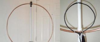
Horizontal bezels are popular. Rick Rogers (KI8GX) experimented with a "ramp" attached to a single mast.
To install the "inclined frame" variant with a perimeter of 41.5 m, a mast with a height of 10 ... 12 meters and an auxiliary support with a height of about two meters are required. Opposite corners of the frame, which is in the shape of a square, are attached to these masts. The distance between the masts is chosen so that the angle of inclination of the frame in relation to the ground is within 30 ... 45 °. The feeding point of the frame is located in the upper corner of the square. The frame is powered by a coaxial cable with a characteristic impedance of 50 Ohm. According to the measurements of the KI8GX in this version, the frame had a VSWR = 1.2 (minimum) at a frequency of 7200 kHz, VSWR = 1.5 (a rather "dull" minimum) at frequencies above 14100 kHz, VSWR = 2.3 over the entire 21 MHz range, SWR = 1.5 (minimum) at 28400 kHz. At the edges of the ranges, the VSWR value did not exceed 2.5. According to the author, a slight increase in the length of the frame will shift the minima closer to the telegraph sections and will make it possible to obtain a VSWR less than two within all operating ranges (except for 21 MHz).
QST # 4 2002
Vertical antenna at 10.15 meters
A simple combined vertical antenna for 10 and 15 m bands can be made both for work in stationary conditions and for out-of-town trips. The antenna is a vertical radiator (Fig. 1) with a blocking filter (ladder) and two resonant counterweights. The trap is tuned to the selected frequency in the range of 10 m, therefore in this range the element L1 is the emitter (see figure). In the range of 15 m, the inductance coil of the ladder is an extension coil and, together with element L2 (see figure), brings the total length of the radiator to 1/4 of the wavelength in the range of 15 m. antenna), fixed on fiberglass tubes. "Trap" antenna is less "capricious" in setting up and operation than an antenna consisting of two adjacent radiators. Antenna dimensions are shown in Fig.2.  The emitter consists of several sections of duralumin pipes of different diameters, connected to one another through adapter sleeves. The antenna is powered by a 50-ohm coaxial cable. To prevent the flow of HF current along the outer side of the cable sheath, power is supplied through a current balun (Fig. 3), made on the FT140-77 ring core.
  The winding consists of four turns of RG174 coaxial cable. The dielectric strength of this cable is sufficient for operation with a transmitter with an output power of up to 150 W. When working with a more powerful transmitter, either a Teflon-insulated cable (eg RG188) or a large diameter cable should be used, which naturally requires an appropriately sized ferrite ring. The balun is installed in a suitable dielectric box:
It is recommended that a 33 kΩ non-inductive two-watt resistor be installed between the vertical radiator and the support pipe on which the antenna is mounted to prevent static build-up on the antenna. It is convenient to place the resistor in the box in which the balun is installed. The design of the ladder can be of any kind.
So, the inductor can be wound on a piece of PVC pipe with a diameter of 25 mm and a wall thickness of 2.3 mm (the lower and upper parts of the radiator are inserted into this pipe). The coil contains 7 turns of copper wire with a diameter of 1.5 mm in varnish insulation, wound with a pitch of 1-2 mm. The required inductance of the coil is 1.16 μH. A high-voltage (6 kV) ceramic capacitor with a capacity of 27 pF is connected in parallel to the coil, and the result is a parallel oscillatory circuit at a frequency of 28.4 MHz. Fine tuning of the resonant frequency of the circuit is carried out by compressing or stretching the turns of the coil. After tuning, the turns are fixed with glue, but it should be borne in mind that an excessive amount of glue applied to the coil can significantly change its inductance and lead to an increase in dielectric losses and, accordingly, a decrease in the antenna efficiency. In addition, the ladder can be made from a coaxial cable by winding 5 turns on a 20 mm PVC pipe, but it is necessary to provide for the possibility of changing the winding pitch to ensure accurate tuning to the required resonant frequency. The design of the trap for its calculation is very convenient to use the Coax Trap program, which can be downloaded from the Internet. Practice shows that such traps work reliably with 100-watt transceivers. To protect the drain from the environment, it is placed in a plastic pipe, which is closed with a plug on top. Counterweights can be made from bare wire 1 mm in diameter and should be spaced as far apart as possible. If a wire in plastic insulation is used for counterweights, then they should be somewhat shortened. So, counterweights made of copper wire with a diameter of 1.2 mm in vinyl insulation with a thickness of 0.5 mm should have a length of 2.5 and 3.43 m for the ranges of 10 and 15 m, respectively. The tuning of the antenna begins in the range of 10 m, after making sure that the trap is tuned to the selected resonant frequency (for example, 28.4 MHz). The minimum SWR in the feeder is achieved by changing the length of the lower (up to the ladder) part of the emitter. If this procedure is unsuccessful, then it will be necessary to change within small limits the angle at which the counterweight is located relative to the emitter, the length of the counterweight and, possibly, its location in space. ) parts of the emitter achieve a minimum SWR. If it is impossible to achieve an acceptable SWR, then the solutions recommended for tuning the 10 m antenna should be applied. In the prototype antenna in the frequency band 28.0-29.0 and 21.0-21.45 MHz, the VSWR did not exceed 1.5.
Tuning Antennas and Loops Using a Jammer
 Any type of relay with an appropriate supply voltage and a normally closed contact can be used to operate this jammer circuit. In this case, the higher the relay supply voltage, the higher the level of noise generated by the generator. To reduce the level of interference to the tested devices, it is necessary to carefully shield the generator, and supply power from a battery or accumulator to prevent interference from entering the network. In addition to setting up anti-jamming devices, such a noise generator can be used to measure and set up high-frequency equipment and its components.
Determination of the resonant frequency of the circuits and the resonant frequency of the antenna
 When using a continuous range survey receiver or wavemeter, you can determine the resonant frequency of the circuit under test from the maximum noise level at the output of the receiver or wavemeter. To eliminate the influence of the generator and receiver on the parameters of the measured circuit, their communication coils should have the minimum possible connection with the circuit.When connecting the interference generator to the tested antenna WA1, it is possible to determine its resonant frequency or frequencies in the same way as measuring the circuit.
I. Grigorov, RK3ZK
T2FD wideband aperiodic antenna
 Due to the large linear dimensions, the construction of antennas at low frequencies causes quite certain difficulties for radio amateurs due to the lack of space necessary for these purposes, the complexity of manufacturing and installing high masts. Therefore, working on surrogate antennas, many use interesting low-frequency bands mainly for local connections with an amplifier “one hundred watts per kilometer”. In the radio amateur literature, there are descriptions of rather effective vertical antennas, which, according to the authors, "practically do not occupy the area." But it is worth remembering that significant space is required to accommodate the counterweight system (without which the vertical antenna is ineffective). Therefore, in terms of the occupied area, it is more advantageous to use linear antennas, especially those made according to the popular "inverted V" type, since only one mast is required for their construction. However, the transformation of such an antenna into a dual-band antenna greatly increases the occupied area, since it is desirable to place radiators of different ranges in different planes. Attempts to use switchable extension elements, tuned power lines and other methods of converting a piece of wire into an all-band antenna (with available suspension heights of 12-20 meters) most often lead to the creation of "super surrogates" by tuning that you can conduct amazing tests of your nervous system. The proposed antenna is not "super efficient", but it allows you to work normally in two or three bands without any switching, is characterized by relative stability of parameters and does not need painstaking tuning. With a high input impedance at low suspension heights, it provides better efficiency than simple wire antennas. This is a somewhat modified widely known T2FD antenna, popular in the late 60s, unfortunately, almost never used today. Obviously, it fell into the category of "forgotten" because of the absorbing resistor, which dissipates up to 35% of the transmitter power. Fearing to lose these percentages, many consider the T2FD to be a frivolous design, although they calmly use a pin with three counterweights on the HF bands, efficiency. which does not always "hold out" to 30%. I had to hear a lot of "cons" in relation to the proposed antenna, often unreasonable. I will try to summarize the pros, thanks to which the T2FD was chosen to work on the low bands. In an aperiodic antenna, which in its simplest form is a conductor with a characteristic impedance Z, loaded on an absorbing resistance Rh = Z, the incident wave, having reached the load Rh, is not reflected, but is completely absorbed. Due to this, the traveling wave mode is established, which is characterized by the constancy of the maximum value of the current Imax along the entire conductor. In fig. 1 (A) shows the current distribution along the half-wave vibrator, and Fig. 1 (B) - along the traveling wave antenna (radiation losses and in the antenna conductor are not conventionally taken into account. The shaded area is called the current area and is used to compare simple wire antennas. In antenna theory, there is the concept of the effective (electrical) antenna length, which is determined by replacing vibrator imaginary, along which the current is distributed evenly, having the same value of Imax as that of the investigated vibrator (ie, the same as in Fig. 1 (B)). The length of the imaginary vibrator is chosen such that the geometric area of the current of the real vibrator was equal to the geometric area of the imaginary. For a half-wave vibrator, the length of the imaginary vibrator, at which the areas of the current are equal, is equal to L / 3.14 [pi], where L is the wavelength in meters. It is not difficult to calculate that the length of the half-wave dipole with geometric dimensions = 42 m (3.5 MHz band) is electrically 26 meters, which is the effective length of the dipole. Returning to Fig. 1 (B), it is easy to find that the effective length of the aperiodic antenna is practically equal to its geometric length. The experiments carried out in the 3.5 MHz range allow us to recommend this antenna to radio amateurs as a good cost-benefit option. An important advantage of the T2FD is its broadband and operability at "ridiculous" suspension heights for low frequency ranges, starting from 12-15 meters. For example, a dipole of the 80-meter range with such a suspension height turns into a "military" anti-aircraft antenna,
  since radiates upward about 80% of the supplied power. The main dimensions and design of the antenna are shown in Fig. 2, In Fig. 3 - the upper part of the mast, where the balancing transformer T and the absorbing resistance R are installed The transformer design in Fig. 4
  The transformer can be made on almost any magnetic circuit with a permeability of 600-2000 NN. For example, a core from TVS of tube TVs or a pair of rings stacked together with a diameter of 32-36 mm. It contains three windings, wound in two wires, for example MGTF-0.75 sq. Mm (used by the author). The cross section depends on the power supplied to the antenna. The wires of the windings are laid tightly, without steps and twists. Cross the wires at the location shown in Figure 4. It is enough to wind 6-12 turns in each winding. If you carefully consider Fig. 4, then the manufacture of the transformer does not cause any difficulties. The core should be protected against corrosion with varnish, preferably with oil or moisture resistant glue. The absorption resistance should theoretically dissipate 35% of the input power. It has been experimentally established that MLT-2 resistors withstand 5-6-fold overloads in the absence of direct current at frequencies of the KB ranges. With a power of 200 W, 15-18 MLT-2 resistors connected in parallel are sufficient. The resulting resistance should be between 360-390 ohms. With the dimensions shown in Fig. 2, the antenna operates in the 3.5-14 MHz ranges. For operation in the 1.8 MHz range, it is desirable to increase the total antenna length to at least 35 meters, ideally 50-56 meters. With the correct implementation of the transformer T, the antenna does not need any tuning, you just need to make sure that the SWR is in the range of 1.2-1.5. Otherwise, the error should be looked for in the transformer. It should be noted that with the popular 4: 1 transformer based on a long line (one winding in two wires), the antenna performance deteriorates sharply, and the VSWR can be 1.2-1.3.
German Quad Antenna at 80,40,20,15,10 and even 2m
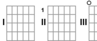
 Most urban radio amateurs face the problem of shortwave antenna placement due to the limited space. But if there is a place for hanging a wire antenna, then the author suggests using it and making "GERMAN Quad / images / book / antenna". He reports that she works well on 6 amateur bands 80, 40, 20, 15, 10 and even 2 meters. The diagram of the antenna is shown in the figure. To make it, you will need exactly 83 meters of copper wire with a diameter of 2.5 mm. The antenna is a 20.7 meter square that hangs horizontally at a height of 30 feet - about 9 meters. The connecting line is made of 75 ohm coaxial cable. According to the author, the antenna has a gain of 6 dB with respect to the dipole. At 80 meters, it has rather high angles of radiation and works well at distances of 700 ... 800 km. Beginning in the 40m range, the angles of emission in the vertical plane decrease. On the horizon, the antenna does not have any directivity priorities. Its author proposes to use it for mobile-stationary work in the field.
3/4 Long Wire antenna
Most of its dipole antennas are based on 3 / 4L wavelengths on either side. We will consider one of them - "Inverted Vee".
The physical length of the antenna is greater than its resonant frequency, increasing the length to 3 / 4L expands the antenna bandwidth compared to a standard dipole and lowers the vertical radiation angles, making the antenna more long-range. In the case of a horizontal arrangement in the form of an angular antenna (half-bomb), it acquires very decent directional properties. All these properties apply to the antenna made in the form of "INV Vee". The antenna input impedance is reduced and special measures are required to match the power line. With a horizontal suspension and a total length of 3 / 2L, the antenna has four main and two minor lobes. The author of the antenna (W3FQJ) provides many calculations and diagrams for different dipole arm lengths and suspension hauls. According to him, he deduced two formulas containing two "magic" numbers, allowing you to determine the length of the dipole arm (in feet) and the length of the feeder in relation to the amateur bands:
L (each half) = 738 / F (in MHz) (in feet feet),
L (feeder) = 650 / F (in MHz) (in feet feet).
For a frequency of 14.2 MHz,
L (each half) = 738 / 14.2 = 52 feet (feet),
L (feeder) = 650 / F = 45 feet 9 inches.
(Conduct the conversion to the metric system yourself, the author of the antenna counts everything in feet). 1 Feet = 30.48 cm
Then for a frequency of 14.2 MHz: L (each half) = (738 / 14.2) * 0.3048 = 15.84 meters, L (feeder) = (650 / F14.2) * 0.3048 = 13.92 meters
P.S. For other selected arm length ratios, the coefficients change.
The 1985 Radio Yearbook published an antenna with a slightly odd name. It is depicted as an ordinary isosceles triangle with a perimeter of 41.4 m and, obviously, therefore, did not attract attention. As it turned out later, it was in vain. I just needed a simple multi-band antenna, and I hung it at a low height - about 7 meters. The length of the supply cable RK-75 is about 56 m (half-wave repeater). The measured SWR values practically coincided with those given in the Yearbook.  Coil L1 is wound on an insulating frame with a diameter of 45 mm and contains 6 turns of PEV-2 wire with a thickness of 2 ... 2 mm. HF transformer T1 is wound with MGSHV wire on a 400NN 60x30x15 mm ferrite ring, contains two windings of 12 turns each. The size of the ferrite ring is not critical and is selected based on the input power. The power cable is connected only as shown in the figure, if you turn it on the other way around, the antenna will not work. The antenna does not require adjustment, the main thing is to accurately maintain its geometric dimensions. When working on a range of 80 m, in comparison with other simple antennas, it loses to transmit - the length is too small. At the reception, the difference is practically not felt. Measurements carried out by G. Bragin's HF bridge ("R-D" No. 11) showed that we are dealing with a non-resonant antenna. The frequency response meter only shows the resonance of the power cable. It can be assumed that the result is a fairly universal antenna (from simple ones), has small geometric dimensions and its SWR practically does not depend on the suspension height. Then it became possible to increase the suspension height up to 13 meters above the ground. And in this case, the SWR value for all the main amateur bands, except for the 80-meter one, did not exceed 1.4. At the eighties, its value ranged from 3 to 3.5 at the upper frequency of the range, therefore, a simple antenna tuner is additionally used to match it. Later we managed to measure SWR on the WARC bands. There the VSWR value did not exceed 1.3. Antenna drawing is shown in the figure.
V. Gladkov, RW4HDK Chapaevsk
GROUND PLANE at 7 MHz
 A vertical antenna has several advantages when operating in low frequency bands. However, due to its large size, it is not possible to install it everywhere. Decreasing the antenna height leads to a drop in radiation resistance and an increase in losses. A wire mesh screen and eight radial wires are used as an artificial "ground". The antenna is powered by a 50-ohm coaxial cable. The VSWR of the antenna tuned with the series capacitor was 1.4. Compared to the previously used "Inverted V" type antenna, this antenna provided a loudness gain of 1 to 3 points in DX operation.
QST, 1969, No. 1 Radio amateur S. Gardner (K6DY / W0ZWK) applied a capacitive load at the end of the "Ground Plane" antenna on the 7 MHz band (see figure), which made it possible to reduce its height to 8 m. The load is a wire cylinder mesh.
P.S. In addition to QST, the description of this antenna was published in the magazine "Radio". In the year 1980, while still a novice radio amateur, he made this version of the GP. I made a capacitive load and artificial earth from a galvanized mesh, since there was plenty of it in those days. Indeed, the antenna outperformed Inv.V. on long runs. But then putting the classic 10 meter GP, I realized that it was not worth bothering about making a container on the top of the pipe, but it would be better to make it two meters longer. The complexity of manufacturing does not pay off the design, not to mention the materials for the manufacture of the antenna.
Antenna DJ4GA
In appearance, it resembles the generatrix of a disc-cone antenna, and its overall dimensions do not exceed the dimensions of a conventional half-wave dipole. Comparison of this antenna with a half-wave dipole having the same suspension height showed that it is somewhat inferior to the dipole for short-range SHORT-SKIP communications, but is much more efficient. it with long-distance communications and with communications carried out with the help of the earth wave. The described antenna has a large bandwidth in comparison with a dipole (by about 20%), which reaches 550 kHz in the range of 40 m (in terms of VSWR up to 2). With a corresponding change in size, the antenna can be used on other bands. The introduction of four notch circuits into the antenna, similar to how it is done in the W3DZZ antenna, allows an efficient multi-band antenna to be realized. The antenna is powered by a coaxial cable with a characteristic impedance of 50 ohms.
P.S. I made this antenna. All dimensions have been consistent, identical to the drawing. It was installed on the roof of a five-story building. When crossing from a triangle of the 80 meter range, located horizontally, on short runs, the loss was 2-3 points. It was checked during communications with the stations of the Far East (Equipment for receiving R-250). I won a maximum of half a point from the triangle. When compared with the classic GP, I lost one and a half points. The equipment was home-made, UW3DI amplifier 2xGU50.
All-wave amateur antenna
 The antenna of the French shortwave radio amateur is described in the magazine "CQ". According to the author of the design, the antenna gives a good result when working on all shortwave amateur bands - 10 m, 15 m, 20 m, 40 m and 80 m.It does not require any particularly careful calculation (except for calculating the length of the dipoles), or precise tuning. It should be installed immediately so that the maximum of the directivity characteristic is oriented in the direction of preferential connections. The feeder of such an antenna can be either two-wire, with a characteristic impedance of 72 ohms, or coaxial, with the same characteristic impedance. For each band, except for the 40 m band, the antenna has a separate half-wave dipole. On the 40-meter range, a 15-meter dipole works well in such an antenna. All dipoles are tuned to the middle frequencies of the corresponding amateur bands and are connected in the center in parallel to two short copper wires. The feeder is soldered to the same wires from below. Three plates of dielectric material are used to insulate the center wires from each other. Holes are made at the ends of the plates for fastening the wires of the dipoles. All the connection points of the wires in the antenna are soldered, and the connection point of the feeder is wrapped with plastic tape to prevent moisture from entering the cable. The calculation of the length L (in m) of each dipole is carried out according to the formula L = 152 / fcp, where fav is the average frequency of the range, MHz. Dipoles are made of copper or bimetallic wire, braces - wire or rope. Antenna height - any, but not less than 8.5 m.
P.S. It was also installed on the roof of a five-story building, the 80-meter dipole was excluded (the size and configuration of the roof did not allow). The masts were made of dry pine, the butt is 10 cm in diameter, the height is 10 meters. Antenna blades were made from a welding cable. The cable was cut, one core was taken, consisting of seven replacement wires. I additionally twisted it a little to increase the density. Proved to be normal, separately suspended dipoles. For work, it is quite an acceptable option.
Switchable dipoles with active power supply
 The switchable antenna is an active powered two-element linear antenna designed to operate in the 7 MHz range. The gain is about 6 dB, the front-to-back ratio is 18 dB, and the sideways ratio is 22-25 dB. DN width at half power level is about 60 degrees For 20 m range L1 = L2 = 20.57 m: L3 = 8.56 m
Bimetal or ant. rope 1.6 ... 3 mm.
I1 = I2 = 14m 75 Ohm cable
I3 = 5.64m 75 Ohm cable
I4 = 7.08m 50 Ohm cable
I5 = arbitrary length 75 ohm cable
K1.1 - HF relay REV-15
 As can be seen from Fig. 1, two active vibrators L1 and L2 are located at a distance L3 (phase shift 72 degrees) from each other. The elements are powered in antiphase, the total phase shift is 252 degrees. K1 provides switching of the direction of radiation by 180 degrees. I3 - phase-shifting loop I4 - quarter-wave matching section. Tuning the antenna consists in adjusting the dimensions of each element in turn to minimize the SWR when the second element is short-circuited through a half-wave repeater 1-1 (1.2). SWR in the middle of the range does not exceed 1.2, at the edges of the range -1.4. The dimensions of the vibrators are given for a suspension height of 20 m. From a practical point of view, especially when working in competitions, a system consisting of two similar antennas located perpendicular to each other and spaced apart in space has proven itself well. In this case, a switch is placed on the roof, instantaneous switching of the DN in one of four directions is achieved. One of the options for the location of antennas among typical urban developments is proposed in Fig. 2 This antenna has been used since 1981, has been repeated many times on different QTHs, with its help tens of thousands of QSOs with more than 300 countries of the world have been carried out.
From the UX2LL website, the original source "Radio No. 5, page 25 S. Firsov. UA3LDH
Beam antenna for 40 meters with switchable radiation pattern
 The antenna schematically shown in the figure is made of copper wire or bimetal with a diameter of 3 ... 5 mm. The matching line is made of the same material. Relays from the RSB radio station are used as switching relays. The matcher uses a variable capacitor from a conventional broadcasting receiver, carefully protected from moisture ingress. The relay control wires are riveted to a nylon stretch cord running along the centerline of the antenna. The antenna has a wide radiation pattern (about 60 °). The front-to-back ratio is within 23 ... 25 dB. The calculated gain is 8 dB. The antenna was operated for a long time at the UK5QBE station.
Vladimir Latyshenko (RB5QW) Zaporozhye, Ukraine
P.S. Outside my roof, as an exit option, out of interest I conducted an experiment with an antenna designed as Inv.V. The rest was gleaned and performed as in this design. The relay used automotive, four-pin, metal case. Since I used a 6ST132 battery for power. TS-450S hardware. One hundred watts. Indeed the result, as they say on the face! When switching to the east, they started calling Japanese stations. VK and ZL, in the direction they were slightly to the south, made their way with difficulty through the stations of Japan. I will not describe the west, everything thundered! The antenna is great! Too bad there is not enough space on the roof!
Multi-band dipole on WARC bands
 The antenna is made of 2 mm copper wire. I have insulating spacers made of 4 mm thick PCB (it is possible from wooden strips) on which insulators for external wiring are fixed with bolts (MB). The antenna is powered by a coaxial cable of the RK75 type of any reasonable length. The lower ends of the insulator bars must be stretched with a nylon cord, then the entire antenna stretches well and the dipoles do not overlap with each other. On this antenna, a number of interesting DX-QSOs were made with all continents using the UA1FA transceiver with one GU29 without RA.
DX 2000 antenna
Shortwave often use vertical antennas. To install such antennas, as a rule, a small free space is required, therefore for some radio amateurs, especially those who live in densely populated urban areas), a vertical antenna is the only opportunity to broadcast on short waves. One of the still little-known vertical antennas operating on all HF bands is DX 2000 antenna. In favorable conditions the antenna can be used for DX - radio communications, but when working with local correspondents (at distances of up to 300 km.) it is inferior to a dipole. As you know, a vertical antenna installed over a well-conductive surface has almost ideal "DX properties", i. E. very low angle of radiation. This does not require a tall mast. Multi-band vertical antennas are typically designed with trap filters and operate in much the same way as single-band quarter-wave antennas. Broadband vertical antennas used in professional HF radio communication have not found a great response in HF radio amateur, but they have interesting properties. On the  The figure shows the most popular vertical antennas among radio amateurs - a quarter-wave radiator, an electrically extended vertical radiator and a vertical radiator with ladders. An example of the so-called. An exponential antenna is shown on the right. Such a bulk antenna has good efficiency in the frequency band from 3.5 to 10 MHz and quite satisfactory matching (VSWR<3) вплоть до верхней границы КВ диапазона (30 МГц). Очевидно, что КСВ = 2 - 3 для транзисторного передатчика очень нежелателен, но, учитывая широкое распространение в настоящее время антенных тюнеров (часто автоматических и встроенных в трансивер), с высоким КСВ в фидере антенны можно мириться. Для лампового усилителя , имеющего в выходном каскаде П - контур, как правило, КСВ = 2 - 3
  is not a problem. The DX 2000 vertical antenna is a hybrid of a narrow-band quarter-wave antenna (Ground plane), tuned to resonance in some amateur bands, and a wide-band exponential antenna. The base of the antenna is a tubular radiator with a length of about 6 m. It is assembled from aluminum pipes with a diameter of 35 and 20 mm, inserted into each other and forming a quarter-wavelength radiator at a frequency of about 7 MHz. Antenna tuning to a frequency of 3.6 MHz is provided by a 75 MkH inductance coil connected in series, to which a thin aluminum tube 1.9 m long is connected. The matching device uses a 10 MkH inductance coil, to the taps of which the cable is connected. in addition, 4 side emitters made of copper wire in PVC insulation with lengths of 2480, 3500, 5000 and 5390 mm are connected to the coil. For fastening, the emitters are lengthened with nylon cords, the ends of which converge under a 75 MkH coil. When working in the range of 80 m, grounding or counterweights are required, at least for protection against thunderstorms. To do this, several galvanized strips can be buried deep in the ground. When mounting the antenna on the roof of a house, it is very difficult to find any "ground" for HF. Even a well-made grounding on the roof does not have a zero potential with respect to the "ground", therefore, it is better to use metal for the grounding device on a concrete roof.
structures with a large surface area. In the used matching device, grounding is connected to the output of the coil, in which the inductance before the outlet, where the cable braid is connected, is 2.2 MkH. Such a low inductance is insufficient to suppress currents flowing along the outer side of the braid of the coaxial cable; therefore, a shut-off choke should be made by winding about 5 m of the cable into a coil with a diameter of 30 cm.  For effective operation of any quarter-wave vertical antenna (including the DX 2000), it is imperative to make a system of quarter-wave counterweights. The DX 2000 antenna was manufactured at the SP3PML radio station (PZK Army Shortwave and Amateur Radio Club).


Antenna design sketch is shown in the figure. The emitter was made of durable duralumin pipes with a diameter of 30 and 20 mm. The braces used to fasten the copper wires-emitters must be resistant to both stretching and weather conditions. The diameter of copper wires should be chosen no more than 3 mm (to limit their own weight), and it is advisable to use wires with insulation, which will ensure resistance to weather conditions. To fix the antenna, use strong insulating ropes that do not stretch when the weather conditions change. The spacers for the copper wires of the emitters should be made of dielectric (for example, PVC pipes with a diameter of 28 mm), but to increase rigidity they can be made from a block of wood or other, as lightweight material as possible. The entire antenna structure is mounted on a steel pipe no longer than 1.5 m, previously rigidly attached to the base (roof), for example, with steel guy wires. The antenna cable can be connected via a connector, which must be electrically isolated from the rest of the structure. For tuning the antenna and matching its impedance with the wave impedance of the coaxial cable, coils with an inductance of 75 MkH (node A) and 10 MkH (node B) are intended. The antenna is tuned to the required sections of the HF bands by selecting the inductance of the coils and the position of the taps. The installation site of the antenna should be free from other structures, best of all, at a distance of 10-12 m, then the influence of these structures on the electrical characteristics of the antenna is small.
Addition to the article:
If the antenna is installed on the roof of an apartment building, its installation height should be more than two meters from the roof to the counterweights (for safety reasons). I strongly do not recommend connecting the antenna ground to the common ground of a residential building or to any fittings that make up the roof structure (in order to avoid huge mutual interference). It is better to use individual grounding, located in the basement of the house. It should be pulled in the communication niches of the building or in a separate pipe pinned to the wall from bottom to top. The use of a lightning arrestor is possible.
V. Bazhenov UA4CGR
How to accurately calculate cable length
Many radio amateurs use 1/4 wave and 1/2 wave coaxial lines. They are needed as resistance transformers for impedance repeaters, phase delay lines for antennas with active power supply, etc. The simplest method, but also the most inaccurate, is the method of multiplying part of the wavelength by factor 0.66, but it is not always suitable when it is necessary to calculate the length of the cable accurately enough, for example 152.2 degrees. Such accuracy is sometimes necessary for antennas with active power supply, where the quality of the antenna depends on the phasing accuracy. The coefficient 0.66 is taken as the average, because for the same dielectric dielectric. permeability can deviate significantly, and therefore the coefficient 0.66 will also deviate. I would like to suggest the method described by ОN4UN. It is simple, but requires instrumentation (a transceiver or oscillator with a digital scale, a good SWR meter and a 50 or 75 ohm dummy load depending on the Z. of the cable) Fig. 1. The figure shows how this method works. The cable from which it is planned to make the desired section must be short-circuited at the end. Next, let's turn to a simple formula. Let's say we need a segment of 73 degrees to work at a frequency of 7.05 MHz. Then our section of cable will be exactly 90 degrees at a frequency of 7.05 x (90/73) = 8.691MHz This means that when tuning the transceiver in frequency, at 8.691MHz, our SWR meter should indicate the minimum SWR because at this frequency, the cable length will be 90 degrees, and for a frequency of 7.05 MHz it will be exactly 73 degrees. Being short-circuited, it will invert the cor. short circuit into infinite resistance and thus will not affect the readings of the SWR meter at a frequency of 8.691 MHz. For these measurements, either a sufficiently sensitive SWR meter is required, or a sufficiently powerful equivalent load, since you will have to increase the power of the transceiver for reliable operation of the SWR meter, if it does not have enough power for normal operation. This method gives very high measurement accuracy, which is limited by the accuracy of the SWR meter and the accuracy of the transceiver scale. For measurements, you can also use the VA1 antenna analyzer, which I already mentioned earlier. An open cable will indicate zero impedance at the calculated frequency. It is very convenient and fast. I think this method will be very useful for radio amateurs.
Alexander Barsky (VAZTTT), vаЗ [email protected] com
Asymmetric GP antenna
 The antenna is (Fig. 1) nothing more than a "grundplain" with an elongated vertical radiator with a height of 6.7 m and four counterweights, each 3.4 m long. A broadband resistance transformer (4: 1) is installed at the feed point. At first glance, the indicated antenna dimensions may appear to be incorrect. However, adding the length of the radiator (6.7 m) and the counterweight (3.4 m), we make sure that the total antenna length is 10.1 m.Considering the shortening factor, this is Lambda / 2 for the 14 MHz band and 1 Lambda for 28 MHz. The resistance transformer (Fig. 2) is made according to the generally accepted technique on a ferrite ring from the OS of a black-and-white TV and contains 2x7 turns. It is installed at the point where the antenna input impedance is about 300 ohms (a similar excitation principle is used in modern versions of the Windom antenna). The average vertical diameter is 35 mm. To achieve resonance at the required frequency and more accurate matching with the feeder, you can change the size and position of the counterweights within a small range. In the author's version, the antenna has a resonance at frequencies of about 14.1 and 28.4 MHz (SWR = 1.1 and 1.3, respectively). If desired, by increasing the dimensions indicated in Fig. 1 by about two times, it is possible to achieve the operation of the antenna in the 7 MHz range. Unfortunately, in this case, the radiation angle in the 28 MHz range will "deteriorate". However, using a U-shaped matching device installed near the transceiver, you can use the author's version of the antenna to work in the 7 MHz range (albeit with a loss of 1.5 ... 2 points in relation to the half-wave dipole), as well as in the 18 , 21, 24 and 27 MHz. For five years of operation, the antenna has shown good results, especially in the 10-meter range.
Shortened antenna 160 meters
For shorter wavelengths, it is often difficult to install full-size antennas for low-frequency HF bands. One of the possible versions of the shortened (approximately two times) dipole of the 160 m range is shown in the figure. The total length of each of the halves of the radiator is about 60 m. They are folded in three, as schematically shown in figure (a) and are held in this position by two end (c) and several intermediate (b) insulators. These insulators, as well as a similar central insulator, are made of a non-hygroscopic dielectric material with a thickness of about 5 mm. The distance between adjacent conductors of the antenna web is 250 mm.
A coaxial cable with a characteristic impedance of 50 ohms is used as a feeder. The antenna is tuned to the middle frequency of the amateur band (or its required section - for example, telegraph) by moving two jumpers connecting its extreme conductors (in the figure they are shown by dashed lines), and observing the symmetry of the dipole. The jumpers must not have electrical contact with the center conductor of the antenna. With the dimensions indicated in the figure, the resonant frequency of 1835 kHz was achieved by installing jumpers at a distance of 1.8 m from the ends of the canvas. The standing wave ratio at the resonant frequency is 1.1. There are no data on its dependence on frequency (i.e., on the antenna bandwidth) in the article.
Antenna 28 and 144 MHz
 Rotating directional antennas are required for efficient operation in the 28 and 144 MHz bands. However, it is usually not possible to use two separate antennas of this type at a radio station. Therefore, the author made an attempt to combine antennas of both bands, making them in the form of a single design. The dual-band antenna is a double "square at 28 MHz, on the carrier traverse of which a nine-element wave channel at 144 MHz is fixed (Fig. 1 and 2). As practice has shown, their mutual influence on each other is insignificant. The influence of the wave channel is compensated by a slight decrease in the perimeters of the frames." square "." Square ", in my opinion, improves the parameters of the wave channel, increasing the gain and suppression of backward radiation. The antennas are powered by scrap feeders from a 75-ohm coaxial cable. The "square" feeder is included in the gap in the lower corner of the vibrator frame (left in Fig. 1). A slight asymmetry with this inclusion causes only a slight skew of the directional pattern in the horizontal plane and does not affect the rest of the parameters. The wave channel feeder is connected through a balancing U-bend ( Fig-3) .As shown by measurements of the SWR in the feeders of both antennas does not exceed 1.1. The antenna mast can be made of steel or duralumin pipe with a diameter of 35-50 mm. A gearbox is attached to the mast, combined with a reversible motor. two metal plates with M5 bolts screwed on a "square" traverse made of pine wood. Traverse section - 40X40 mm. At its ends, crosses are reinforced, which are supported by eight wooden poles "square" with a diameter of 15-20 mm. The frames are made of bare copper wire with a diameter of 2 mm (you can use a wire PEV-2 1.5-2 mm). The perimeter of the reflector frame is 1120 cm, vibrator 1056 cm. The wave channel can be made of copper or brass tubes or rods. Its traverse is fixed on the traverse "square" with two brackets. Antenna settings have no special features. With an exact repetition of the recommended dimensions, it may not be needed. The antennas on the RA3XAQ have shown good results over the years. A lot of DX connections were made at 144 MHz - with Bryansk, Moscow, Ryazan, Smolensk, Lipetsk, Vladimir. More than 3.5 thousand QSOs were established at 28 MHz, among them - with VP8, CX, LU, VK, KW6, ZD9, etc. The design of the dual-band antenna was repeated three times by Kaluga radio amateurs (RA3XAC, RA3XAS, RA3XCA) and also received positive ratings ...
P.S. In the eighties of the last century, there was exactly such an antenna. In osnovnoy he made for work through low-orbit satellites ... RS-10, RS-13, RS-15. I used UW3DI with Zhutyaevsky transverter, and received R-250. Everything worked out well with ten watts. The squares on the top ten worked well, a lot of VK, ZL, JA, etc. ... And the passage was wonderful then!
Shortwave antennas
Practical amateur radio antenna designs
This section presents a large number of different practical antenna designs and other related devices. To facilitate the search, you can use the button "View a list of all published antennas". More on the topic - see the CATEGORY with a regular replenishment of new publications in the subheading.
Off-center dipole
Many shortwave operators are interested in simple HF antennas that provide operation without any switching on several amateur bands. The most famous of these antennas is the Windom with a single-wire feeder. But the payment for the simplicity of the manufacture of this antenna was and remains the inevitable interference with television and radio broadcasting when powered by a single-wire feeder and the accompanying clarification of relations with neighbors.
The idea of Windom-dipoles seems to be simple. By shifting the feed point from the center of the dipole, you can find a ratio of the lengths of the arms at which the input resistances on several ranges become quite close. Most often, they are looking for dimensions at which it is close to 200 or 300 Ohm, and matching with low-impedance power cables is carried out using balun transformers (BALUN) with a transformation ratio of 1: 4 or 1: 6 (for a cable with a characteristic impedance of 50 Ohm). This is how, for example, the antennas FD-3 and FD-4 are made, which are produced, in particular, in series in Germany.
Radio amateurs design similar antennas on their own. Certain difficulties, however, arise in the manufacture of balancing transformers, in particular, for operation in the entire short-wavelength range and when using power exceeding 100 W.
A more serious problem is that such transformers normally only operate on a matched load. And this condition is obviously not met in this case - the input impedance of such antennas is really close to the required values of 200 or 300, but obviously differs from them, and on all ranges. The consequence of this is that to some extent this design retains the antenna effect of the feeder despite the use of a matching transformer and a coaxial cable. As a result, the use of balun transformers in these antennas, even of a rather complex design, does not always completely solve the TVI problem.
Aleksandr Shevelev (DL1BPD) succeeded, using line matching devices, to develop a version of Windom-dipole matching, which use power through a coaxial cable and are devoid of this drawback. They were described in the magazine “Radio amateur. Bulletin SRR "(2005, March, pp. 21, 22).
Calculations show that the best result is obtained when using lines with characteristic impedances of 600 and 75 ohms. A line with a characteristic impedance of 600 ohms adjusts the input impedance of the antenna on all operating ranges to a value of approximately 110 ohms, and a 75 ohm line transforms this impedance to a value close to 50 ohms.

Let's consider a variant of such a Windom-dipole (ranges of 40-20-10 meters). In fig. 1 shows the lengths of the arms and dipole lines on these ranges for a wire with a diameter of 1.6 mm. The total length of the antenna is 19.9 m. When using an insulated antenna cord, the arm lengths are made slightly shorter. A line with a characteristic impedance of 600 ohms and a length of approximately 1.15 meters is connected to it, and a coaxial cable with a characteristic impedance of 75 ohms is connected to the end of this line.
The latter, with a cable shortening factor equal to K = 0.66, has a length of 9.35 m. The reduced line length with a characteristic impedance of 600 ohms corresponds to a shortening factor K = 0.95. With such dimensions, the antenna is optimized for operation in the frequency bands 7 ... 7.3 MHz, 14 ... 14.35 MHz and 28 ... 29 MHz (with a minimum SWR at a frequency of 28.5 MHz). The calculated SWR graph of this antenna for an installation height of 10 m is shown in Fig. 2.

Using a cable with a characteristic impedance of 75 ohms is generally not the best option in this case. Lower VSWR values can be obtained using a cable with a characteristic impedance of 93 ohms or a line with a characteristic impedance of 100 ohms. It can be made from a coaxial cable with a characteristic impedance of 50 Ohm (for example, http://dx.ardi.lv/Cables.html). If a line with a characteristic impedance of 100 Ohm from a cable is used, it is advisable to turn on BALUN 1: 1 at its end.
To reduce the level of interference from the part of the cable with a characteristic impedance of 75 Ohm, a choke should be made - a coil (coil) Ø 15-20 cm, containing 8-10 turns.
The directional pattern of this antenna practically does not differ from the directional pattern of a similar Windom-dipole with a balun. Its efficiency should be slightly higher than that of antennas using BALUN, and tuning should be no more difficult than tuning conventional Windom dipoles.
Vertical dipole
It is well known that for long-distance operation a vertical antenna has an advantage, since its directional pattern in the horizontal plane is circular, and the main lobe of the pattern in the vertical plane is pressed to the horizon and has a low level of radiation to the zenith.
However, the manufacture of a vertical antenna is associated with a number of design problems. The use of aluminum pipes as a vibrator and the need for its efficient operation to install at the base of the "vertical" a system of "radials" (counterweights), consisting of a large number of wires with a length of a quarter wave. If you use not a pipe, but a wire as a vibrator, the mast supporting it must be made of a dielectric and all the guy wires supporting the dielectric mast must also be dielectric, or broken into non-resonant sections by insulators. All this is associated with costs and often constructively impracticable, for example, due to the lack of the necessary area for placing the antenna. Do not forget that the input impedance of the "verticals" is usually below 50 Ohm, and this will also require its coordination with the feeder.
On the other hand, horizontal dipole antennas, which include Inverted V antennas, are structurally very simple and cheap, which explains their popularity. The vibrators of such antennas can be made of almost any wire, and the masts for their installation can also be made of any material. The input impedance of the horizontal dipoles or Inverted V is close to 50 ohms, and it is often possible to do without additional termination. The directional patterns of the Inverted V antenna are shown in Fig. one.

The disadvantages of horizontal dipoles include their non-circular radiation pattern in the horizontal plane and a large radiation angle in the vertical plane, which is generally acceptable for operation on short paths.
Turn the usual horizontal wire dipole vertically by 90 degrees. and we get a vertical full-size dipole. To reduce its length (in this case, the height), we use the well-known solution - "dipole with bent ends". For example, a description of such an antenna is in the files of the library of I. Goncharenko (DL2KQ) for the MMANA-GAL program - AntShortCurvedCurved dipole.maa. By bending back some of the vibrators, we, of course, lose some in the antenna gain, but we significantly gain in the required mast height. The bent ends of the vibrators should be located one above the other, while the radiation of vibrations with horizontal polarization, which is harmful in our case, is compensated. A sketch of the proposed version of the antenna, called by the authors Curved Vertical Dipole (CVD), is shown in Fig. 2.

Initial conditions: a dielectric mast 6 m high (fiberglass or dry wood), the ends of the vibrators are pulled by a dielectric cord (fishing line or nylon) at a slight angle to the horizon. The vibrator is made of copper wire with a diameter of 1 ... 2 mm, bare or insulated. At the break points, the vibrator wire is attached to the mast.
If we compare the calculated parameters of the Inverted V and CVD antennas for the 14 MHz band, it is easy to see that due to the shortening of the radiating part of the dipole, the CVD antenna has a 5 dB lower gain, however, at a radiation angle of 24 degrees. (CVD maximum gain) the difference is only 1.6 dB. In addition, the Inverted V antenna has a horizontal irregularity of up to 0.7 dB, i.e. in some directions it outperforms CVD in gain by only 1 dB. Since the calculated parameters of both antennas turned out to be close, the final conclusion could only be made by experimental verification of CVD and practical work on the air. Three CVD antennas were manufactured for the 14, 18 and 28 MHz bands according to the dimensions shown in the table. They all had the same design (see Fig. 2). The sizes of the upper and lower arms of the dipole are the same. Our vibrators were made of P-274 field telephone cable, insulators were made of plexiglass. The antennas were lifted onto a 6 m high fiberglass mast, with the top of each antenna being 6 m above the ground. The bent parts of the vibrators were pulled back with a nylon cord at an angle of 20-30 degrees. to the horizon, since we did not have tall items for fastening the guy wires. The authors made sure (this was also confirmed by modeling) that the deviation of the bent sections of the vibrators from the horizontal position by 20-30 degrees. practically does not affect the characteristics of the CVD.
Simulations in the MMANA software show that such a curved vertical dipole easily matches a 50 ohm coaxial cable. It has a small angle of radiation in the vertical plane and a circular radiation pattern in the horizontal plane (Fig. 3).

The design simplicity made it possible to change one antenna to another within five minutes, even in the dark. The same coaxial cable was used to power all CVD antenna variants. He approached the vibrator at an angle of about 45 degrees. To suppress the common-mode current, a tubular ferrite magnetic circuit (filter-latch) is installed on the cable near the connection point. It is advisable to install several similar magnetic circuits on a 2 ... 3 m long cable section close to the antenna web.
Since the antennas were made of vole, its insulation increased the electrical length by about 1%. Therefore, antennas made according to the dimensions given in the table needed some shortening. The adjustment was carried out by adjusting the length of the lower bent section of the vibrator, easily accessible from the ground. By folding part of the length of the lower bent wire in two, you can fine-tune the resonant frequency by moving the end of the bent section along the wire (a kind of trimming loop).
The resonant frequency of the antennas was measured with an MF-269 antenna analyzer. All antennas had a clearly defined SWR minimum in the limits of the amateur bands, not exceeding 1.5. For example, a 14 MHz antenna had a minimum SWR at a frequency of 14155 kHz of 1.1, and a bandwidth of 310 kHz for a SWR of 1.5 and 800 kHz for a SWR of 2.
For comparative tests, an Inverted V of the 14 MHz band was used, mounted on a metal mast with a height of 6 m. The ends of the vibrators were at a height of 2.5 m above the ground.
To obtain objective estimates of the signal level in QSB conditions, the antennas were repeatedly switched from one to another with a switching time of no more than one second.
table

Radio communications were carried out in SSB mode with a transmitter power of 100 W on routes ranging from 80 to 4600 km. On the 14 MHz band, for example, all correspondents who were at a distance of more than 1000 km noted that the signal level with the CVD antenna was one or two points higher than with the Inverted V. At a distance of less than 1000 km, Inverted V had some minimal advantage. ...

These tests were carried out during a period of relatively poor conditions for the passage of radio waves on the HF bands, which explains the lack of more distant communications.
During the absence of ionospheric propagation in the 28 MHz range, we conducted several surface wave radio communications from our QTH with this antenna with Moscow shortwave wavelengths at a distance of about 80 km. On a horizontal dipole, even raised slightly above the CVD antenna, none of them could be heard.
The antenna is made from cheap materials and does not require a lot of space for placement.
When used as guy lines, nylon fishing line, it may well disguise itself as a flagpole (a cable divided into sections of 1.5 ... 3 m by ferrite chokes, while it can go along or inside the mast and be unobtrusive), which is especially valuable with unfriendly neighbors in the country (fig. 4).
Files in the .maa format for independent study of the properties of the described antennas are located.
Vladislav Shcherbakov (RU3ARJ), Sergey Filippov (RW3ACQ),
Moscow city
A modification of the T2FD antenna, known to many, is proposed, which allows covering the entire range of radio amateur HF frequencies, losing quite a bit to a half-wave dipole in the 160 meter range (0.5 dB on near and about 1.0 dB on DX paths).  With an exact repetition, the antenna starts working immediately and does not need tuning. The peculiarity of the antenna is noticed: static interference is not perceived, and in comparison with the classical half-wave dipole. In this performance, the reception of the broadcast turns out to be quite comfortable. Very weak DX stations are normally listened to, especially in the low frequency ranges.
Long-term operation of the antenna (more than 8 years) allowed it to be deservedly attributed to low-noise receiving antennas. Otherwise, in terms of efficiency, this antenna is practically not inferior to a band half-wave dipole or Inverted Vee on any of the bands from 3.5 to 28 MHz.
And one more observation (based on feedback from distant correspondents) - there are no deep QSBs during the communication. Of the 23 modifications of this antenna produced, the one proposed here deserves special attention and can be recommended for massive repetition. All proposed dimensions of the antenna-feeder system are calculated and precisely verified in practice.
Antenna strip
The vibrator dimensions are shown in the figure. The halves (both) of the vibrator are symmetrical, the extra length of the "inner corner" is cut in place, and a small platform (always insulated) is also attached there to connect to the supply line. Ballast resistor 240 Ohm, foil (green), rated for 10 W. You can also use any other resistor of the same power, the main thing is that the resistance must be non-inductive. Copper wire - insulated, with a cross section of 2.5 mm. Spacers - wooden slats in a section with a section of 1 x 1 cm, varnished. The distance between the holes is 87 cm. We use a nylon cord on the stretch marks.
Overhead power line
For the power line, we use a PV-1 copper wire with a cross section of 1 mm, vinyl plastic spacers. The distance between the conductors is 7.5 cm. The length of the entire line is 11 meters.
Author's installation option
A metal, bottom-grounded mast is used. The mast is installed on a 5-storey building. Mast - 8 meters from a pipe Ø 50 mm. The ends of the antenna are placed 2 m from the roof. The core of the matching transformer (SHPTR) is made of the TVS-90LTs5 line transformer. The coils are removed there, the core itself is glued with Supermoment glue to a solid state and with three layers of varnished cloth.
Winding is made in 2 wires without twisting. The transformer contains 16 turns of a single-core insulated copper wire Ø 1 mm. The transformer has a square (sometimes rectangular) shape, so 4 pairs of turns are wound on each of the 4 sides - the best version of the current distribution.
VSWR in the entire range is from 1.1 to 1.4. ShPTR is placed in a tin screen, well soldered with a braid of the feeder. From the inside, the middle terminal of the transformer winding is reliably soldered to it.
After assembly and installation, the antenna will work immediately and in almost any conditions, that is, located low above the ground or above the roof of the house. She has a very low level of TVI (television interference), and this may additionally interest radio amateurs working from villages or summer residents.
Antenna Loop Feed Array Yagi 50 MHz
 Antennas Yagi (Yagi) with a loop vibrator located in the plane of the antenna are called LFA Yagi (Loop Feed Array Yagi) and are characterized by a wider operating frequency range than conventional Yagi. One of the popular Yagi LFAs is Justin Johnson's 5-piece construction (G3KSC) for the 6-meter range.
Antenna layout, distances between elements and dimensions of elements are shown in the table below and in the drawing.
The dimensions of the elements, the distances to the reflector and the diameters of the aluminum tubes from which the elements are made according to the table: The elements are installed on a traverse with a length of about 4.3 m from a square aluminum profile with a cross section of 90 × 30 mm through insulating transition strips. The vibrator is powered by a 50 ohm coaxial cable through a balun 1:1.
Antenna tuning for the minimum SWR in the middle of the range is performed by adjusting the position of the end U-shaped parts of the vibrator from tubes with a diameter of 10 mm. It is necessary to change the position of these inserts symmetrically, that is, if the right insert is pushed out by 1 cm, then the left one must be pushed out by the same amount.
SWR meter on strip lines
 SWR meters, widely known from the amateur radio literature, are made using directional couplers and are single-layer
  coil or ferrite ring core with multiple turns of wire. These devices have a number of disadvantages, the main of which is that when measuring high powers, a high-frequency "pickup" appears in the measuring circuit, which requires additional costs and efforts to screen the detector part of the SWR meter to reduce the measurement error, and with the formal attitude of the radio amateur to manufacturing instrument, the SWR meter can cause the impedance of the feed line to change depending on the frequency. The offered SWR meter based on strip-line directional couplers is free from such disadvantages, it is designed as a separate independent device and allows you to determine the ratio of direct and reflected waves in the antenna circuit with an input power of up to 200 W in a frequency range of 1 ... 50 MHz with a characteristic impedance of a feeder line 50 Ohm. If you only need an indicator of the transmitter output power or monitor the antenna current, you can use the following device: When measuring the SWR in lines with a characteristic impedance other than 50 Ohm, the values of the resistors R1 and R2 should be changed to the value of the characteristic impedance of the measured line.
SWR meter design
 The SWR meter is made on a 2 mm thick double-sided foil-clad PTFE board. As a replacement, it is possible to use double-sided fiberglass.
L2 line is made on the back side of the board and is shown with a dashed line. Its dimensions are 11 × 70 mm. Caps are inserted into the holes of line L2 for connectors XS1 and XS2, which are flared and soldered together with L2. The common bus on both sides of the board has the same configuration and is shaded in the board diagram. In the corners of the board, holes are drilled into which pieces of wire with a diameter of 2 mm are inserted, soldered on both sides of the common bus. Lines L1 and L3 are located on the front side of the board and have dimensions: straight section 2 × 20 mm, distance between them is 4 mm and are located symmetrically to the longitudinal axis of line L2. The displacement between them along the longitudinal axis L2 is 10 mm. All radioelements are located on the side of the L1 and L2 strip lines and are soldered overlapping directly to the printed conductors of the SWR meter board. The printed conductors of the board should be silver-plated. The assembled board is soldered directly to the contacts of the XS1 and XS2 connectors. The use of additional connecting leads or coaxial cable is not permitted. The finished SWR meter is placed in a non-magnetic box 3 ... 4 mm thick. The common bus of the SWR meter board, the device body and connectors are electrically connected to each other. The SWR is counted as follows: in the S1 "Straight" position, using R3, set the microammeter needle to the maximum value (100 μA) and turning S1 into "Reverse", the SWR value is measured. In this case, the reading of the device 0 μA corresponds to SWR 1; 10 μA - VSWR 1.22; 20 μA - VSWR 1.5; 30 μA - VSWR 1.85; 40 μA - VSWR 2.33; 50 μA - VSWR 3; 60 μA - VSWR 4; 70 μA - VSWR 5.67; 80 μA - 9; 90 μA - VSWR 19.
HF Nine Band Antenna
The antenna is a variation of the well-known "WINDOM" multi-band antenna, in which the feed point is off-center. In this case, the input impedance of the antenna in several amateur KB bands is approximately 300 ohms,  which makes it possible to use both a single wire and a two-wire line with a corresponding characteristic impedance as a feeder, and, finally, a coaxial cable connected through a matching transformer. In order for the antenna to work in all nine amateur KB bands (1.8; 3.5; 7; 10; 14; 18; 21; 24 and 28 MHz), essentially two WINDOM antennas are connected in parallel (see above Fig. a): one with a total length of about 78 m (l / 2 for the 1.8 MHz band), and the other with a total length of about 14 m (l / 2 for the 10 MHz band and l for the 21 MHz band). Both emitters are powered by a single coaxial cable with a characteristic impedance of 50 ohms. The matching transformer has a resistance transformation ratio of 1: 6.
The approximate location of the antenna radiators in plan is shown in Fig. b. 
When the antenna was installed at a height of 8 m above a well-conducting "ground", the standing wave ratio in the 1.8 MHz range did not exceed 1.3, in the 3.5, 14.21, 24 and 28 MHz ranges - 1.5, in the 7.10 and 18 ranges. MHz - 1.2. In the 1.8, 3.5 MHz bands, and to some extent in the 7 MHz band with a suspension height of 8 m, the dipole is known to radiate mainly at large angles to the horizon. Consequently, in this case, the antenna will be effective only when conducting short-range communications (up to 1500 km).
The diagram for connecting the windings of the matching transformer to obtain a transformation ratio of 1: 6 is shown in Fig. C.

Windings I and II have the same number of turns (as in a conventional transformer with a transformation ratio of 1: 4). If the total number of turns of these windings (and it depends primarily on the size of the magnetic circuit and its initial magnetic permeability) is equal to n1, then the number of turns n2 from the junction point of windings I and II to the tap is calculated by the formula n2 = 0.82n1.t
 Horizontal bezels are popular. Rick Rogers (KI8GX) experimented with a "ramp" attached to a single mast.
To install the "inclined frame" variant with a perimeter of 41.5 m, a mast with a height of 10 ... 12 meters and an auxiliary support with a height of about two meters are required. Opposite corners of the frame, which is in the shape of a square, are attached to these masts. The distance between the masts is chosen so that the angle of inclination of the frame in relation to the ground is within 30 ... 45 °. The feeding point of the frame is located in the upper corner of the square. The frame is powered by a coaxial cable with a characteristic impedance of 50 Ohm. According to the KI8GX measurements in this version, the frame had a SWR = 1.2 (minimum) at 7200 kHz, SWR = 1.5 (rather "dull" minimum) at frequencies above 14100 kHz, SWR = 2.3 over the entire 21 MHz range, SWR = 1.5 (minimum) at 28400 kHz. At the edges of the ranges, the VSWR value did not exceed 2.5. According to the author, a slight increase in the length of the frame will shift the minima closer to the telegraph sections and will make it possible to obtain VSWR less than 2 within all operating ranges (except for 21 MHz).
QST # 4 2002
Vertical antenna at 10, 15 meters
 A simple combined vertical antenna for 10 and 15 m bands can be made both for work in stationary conditions and for out-of-town trips. The antenna is a vertical radiator (Fig. 1) with a blocking filter (ladder) and two resonant counterweights. The trap is tuned to the selected frequency in the range of 10 m, therefore in this range the element L1 is the emitter (see figure). In the range of 15 m, the inductance coil of the ladder is lengthening and, together with the L2 element (see figure), brings the total length of the radiator to 1/4 of the wavelength in the 15 m range. antenna) mounted on fiberglass tubes. A "trap" antenna is less "capricious" in setting up and operating than an antenna consisting of two adjacent radiators. Antenna dimensions are shown in Fig.2.
  The emitter consists of several sections of duralumin pipes of different diameters, connected to one another through adapter sleeves. The antenna is powered by a 50-ohm coaxial cable. To prevent the flow of HF current along the outer side of the cable sheath, power is supplied through a current balun (Fig. 3), made on the FT140-77 ring core.
  The winding consists of four turns of RG174 coaxial cable. The dielectric strength of this cable is sufficient for operation with a transmitter with an output power of up to 150 W. When working with a more powerful transmitter, either a Teflon-insulated cable (eg RG188) or a large diameter cable should be used, which naturally requires an appropriately sized ferrite ring. The balun is installed in a suitable dielectric box:
 It is recommended that a 33 kΩ non-inductive two-watt resistor be installed between the vertical radiator and the support pipe on which the antenna is mounted to prevent static build-up on the antenna. It is convenient to place the resistor in the box in which the balun is installed. The design of the ladder can be of any kind.
So, the inductor can be wound on a piece of PVC pipe with a diameter of 25 mm and a wall thickness of 2.3 mm (the lower and upper parts of the radiator are inserted into this pipe). The coil contains 7 turns of copper wire with a diameter of 1.5 mm in varnish insulation, wound with a pitch of 1-2 mm. The required inductance of the coil is 1.16 μH. A high-voltage (6 kV) ceramic capacitor with a capacity of 27 pF is connected in parallel to the coil, and the result is a parallel oscillatory circuit at a frequency of 28.4 MHz.
Fine tuning of the resonant frequency of the circuit is carried out by compressing or stretching the turns of the coil. After tuning, the turns are fixed with glue, but it should be borne in mind that an excessive amount of glue applied to the coil can significantly change its inductance and lead to an increase in dielectric losses and, accordingly, a decrease in the antenna efficiency. In addition, the ladder can be made from a coaxial cable by winding 5 turns on a 20 mm PVC pipe, but it is necessary to provide for the possibility of changing the winding pitch to ensure accurate tuning to the required resonant frequency. The design of the trap for its calculation is very convenient to use the Coax Trap program, which can be downloaded from the Internet.
Practice shows that such traps work reliably with 100-watt transceivers. To protect the drain from the environment, it is placed in a plastic pipe, which is closed with a plug on top. Counterweights can be made from bare wire 1 mm in diameter and should be spaced as far apart as possible. If a wire in plastic insulation is used for counterweights, then they should be somewhat shortened. So, counterweights made of copper wire with a diameter of 1.2 mm in vinyl insulation with a thickness of 0.5 mm should have a length of 2.5 and 3.43 m for the ranges of 10 and 15 m, respectively.
The tuning of the antenna begins in the range of 10 m, after making sure that the trap is tuned to the selected resonant frequency (for example, 28.4 MHz). The minimum SWR in the feeder is achieved by changing the length of the lower (up to the ladder) part of the emitter. If this procedure is unsuccessful, then it will be necessary to change within small limits the angle at which the counterweight is located relative to the emitter, the length of the counterweight and, possibly, its location in space. ) parts of the emitter achieve a minimum SWR. If it is impossible to achieve an acceptable SWR, then the solutions recommended for tuning the antenna in the 10 m range should be applied. In the prototype antenna in the 28.0-29.0 and 21.0-29.45 MHz frequency bands, the SWR did not exceed 1.5.
Tuning Antennas and Loops Using a Jammer
 Any type of relay with an appropriate supply voltage and with a normally closed contact can be used to operate this jammer circuit. In this case, the higher the relay supply voltage, the higher the level of noise generated by the generator. To reduce the level of interference to the tested devices, it is necessary to carefully shield the generator, and supply power from a battery or accumulator to prevent interference from entering the network. In addition to setting up noise-immune devices, with such a noise generator, you can measure and set up high-frequency equipment and its components.
Determination of the resonant frequency of the circuits and the resonant frequency of the antenna

 When using a survey receiver with a continuous range or wavemeter, you can determine the resonant frequency of the circuit under test from the maximum noise level at the output of the receiver or wavemeter. To eliminate the influence of the generator and receiver on the parameters of the measured circuit, their communication coils should have the minimum possible connection with the circuit.When connecting the interference generator to the tested antenna WA1, it is possible to determine its resonant frequency or frequencies in the same way as measuring the circuit.
I. Grigorov, RK3ZK
T2FD wideband aperiodic antenna
 Due to the large linear dimensions, the construction of antennas at low frequencies causes quite certain difficulties for radio amateurs due to the lack of space necessary for these purposes, the complexity of manufacturing and installing high masts. Therefore, working on surrogate antennas, many use interesting low-frequency bands mainly for local connections with an amplifier “one hundred watts per kilometer”.
In the radio amateur literature, there are descriptions of rather effective vertical antennas, which, according to the authors, "practically do not occupy the area." But it is worth remembering that significant space is required to accommodate the counterweight system (without which the vertical antenna is ineffective). Therefore, in terms of the occupied area, it is more advantageous to use linear antennas, especially those made according to the popular "inverted V" type, since only one mast is required for their construction. However, the transformation of such an antenna into a dual-band antenna greatly increases the occupied area, since it is desirable to place radiators of different ranges in different planes.
Attempts to use switchable extension elements, tuned power lines and other methods of converting a piece of wire into an all-band antenna (with available suspension heights of 12-20 meters) most often lead to the creation of "super surrogates" by tuning that you can conduct amazing tests of your nervous system.
The proposed antenna is not "super efficient", but it allows you to work normally in two or three bands without any switching, is characterized by relative stability of parameters and does not need painstaking tuning. With a high input impedance at low suspension heights, it provides better efficiency than simple wire antennas. This is a somewhat modified widely known T2FD antenna, popular in the late 60s, unfortunately, almost never used today. Obviously, it fell into the category of "forgotten" because of the absorbing resistor, which dissipates up to 35% of the transmitter power. Fearing to lose these percentages, many consider the T2FD to be a frivolous design, although they calmly use a pin with three counterweights on the HF bands, efficiency. which does not always "hold out" to 30%. I had to hear a lot of "cons" in relation to the proposed antenna, often unreasonable. I will try to summarize the pros, thanks to which the T2FD was chosen to work on the low bands.
In an aperiodic antenna, which in its simplest form is a conductor with a characteristic impedance Z, loaded on an absorbing resistance Rh = Z, the incident wave, having reached the load Rh, is not reflected, but is completely absorbed. Due to this, the traveling wave mode is established, which is characterized by the constancy of the maximum value of the current Imax along the entire conductor. In fig. 1 (A) shows the current distribution along the half-wave vibrator, and Fig. 1 (B) - along the traveling wave antenna (radiation losses and in the antenna conductor are not conventionally taken into account. The shaded area is called the current area and is used to compare simple wire antennas.
In the theory of antennas, there is the concept of the effective (electrical) length of the antenna, which is determined by the replacement of a real vibrator by an imaginary one, along which the current is distributed evenly, having the same value of Imax,  as in the investigated vibrator (ie, the same as in Fig. 1 (B)). The length of the imaginary vibrator is chosen such that the geometric area of the current of the real vibrator is equal to the geometric area of the imaginary one. For a half-wave vibrator, the length of the imaginary vibrator, at which the current areas are equal, is equal to L / 3.14 [pi], where L is the wavelength in meters. It is not difficult to calculate that the length of a half-wave dipole with geometric dimensions = 42 m (3.5 MHz range) is electrically equal to 26 meters, which is the effective length of the dipole. Returning to fig. 1 (B), it is easy to find that the effective length of the aperiodic antenna is practically equal to its geometric length.
The experiments carried out in the 3.5 MHz range allow us to recommend this antenna to radio amateurs as a good cost-benefit option. An important advantage of the T2FD is its broadband and operability at "ridiculous" suspension heights for low frequency ranges, starting from 12-15 meters. For example, a dipole of the 80-meter range with such a suspension height turns into a "military" anti-aircraft antenna, since radiates upward about 80% of the supplied power. The main dimensions and design of the antenna are shown in Fig. 2, In Fig. 3 - the upper part of the mast, where the balancing transformer T and the absorbing resistance R are installed The transformer design in Fig. 4 
The transformer can be made on almost any magnetic circuit with a permeability of 600-2000 NN. For example, a core from TVS of tube TVs or a pair of rings stacked together with a diameter of 32-36 mm. It contains three windings, wound in two wires, for example MGTF-0.75 sq. Mm (used by the author). The cross section depends on the power supplied to the antenna. The wires of the windings are laid tightly, without steps and twists. Cross the wires at the location shown in Figure 4.
It is enough to wind 6-12 turns in each winding. If you carefully consider Fig. 4, then the manufacture of the transformer does not cause any difficulties. The core should be protected against corrosion with varnish, preferably with oil or moisture resistant glue. The absorption resistance should theoretically dissipate 35% of the input power. It has been experimentally established that MLT-2 resistors withstand 5-6-fold overloads in the absence of direct current at frequencies of the KB ranges. With a power of 200 W, 15-18 MLT-2 resistors connected in parallel are sufficient. The resulting resistance should be between 360-390 ohms. With the dimensions shown in Fig. 2, the antenna operates in the 3.5-14 MHz ranges.
For operation in the 1.8 MHz range, it is desirable to increase the total antenna length to at least 35 meters, ideally 50-56 meters. With the correct implementation of the transformer T, the antenna does not need any tuning, you just need to make sure that the SWR is in the range of 1.2-1.5. Otherwise, the error should be looked for in the transformer. It should be noted that with the popular 4: 1 transformer based on a long line (one winding in two wires), the antenna performance deteriorates sharply, and the VSWR can be 1.2-1.3.
German Quad Antenna at 80, 40, 20, 15, 10 and even 2 m
Most urban radio amateurs face the problem of shortwave antenna placement due to the limited space.
But if there is a place for hanging a wire antenna, then the author suggests using it and making "GERMAN Quad / images / book / antenna". He reports that she works well on 6 amateur bands 80, 40, 20, 15, 10 and even 2 meters. The diagram of the antenna is shown in the figure. To make it, you will need exactly 83 meters of copper wire with a diameter of 2.5 mm. The antenna is a 20.7 meter square that hangs horizontally at a height of 30 feet - about 9 meters. The connecting line is made of 75 ohm coaxial cable. According to the author, the antenna has a gain of 6 dB with respect to the dipole. At 80 meters it has rather high angles of radiation and works well at distances of 700 ... 800 km. Beginning in the 40m range, the angles of emission in the vertical plane decrease. On the horizon, the antenna does not have any directivity priorities. Its author proposes to use it for mobile-stationary work in the field.
3/4 Long Wire antenna
 Most of its dipole antennas are based on 3 / 4L wavelengths on either side. We will consider one of them - "Inverted Vee".
The physical length of the antenna is greater than its resonant frequency, increasing the length to 3 / 4L expands the antenna bandwidth compared to a standard dipole and lowers the vertical radiation angles, making the antenna more long-range. In the case of a horizontal arrangement in the form of an angular antenna (half-bomb), it acquires very decent directional properties. All these properties apply to the antenna made in the form of "INV Vee". The antenna input impedance is reduced and special measures are required to match the power line. With a horizontal suspension and a total length of 3 / 2L, the antenna has four main and two minor lobes. The author of the antenna (W3FQJ) provides many calculations and diagrams for different dipole arm lengths and suspension hauls. According to him, he deduced two formulas containing two "magic" numbers, allowing you to determine the length of the dipole arm (in feet) and the length of the feeder in relation to the amateur bands:
L (each half) = 738 / F (in MHz) (in feet feet),
L (feeder) = 650 / F (in MHz) (in feet feet).
For a frequency of 14.2 MHz,
L (each half) = 738 / 14.2 = 52 feet (feet),
L (feeder) = 650 / F = 45 feet 9 inches.
(Conduct the conversion to the metric system yourself, the author of the antenna counts everything in feet). 1 Feet = 30.48 cm
Then for a frequency of 14.2 MHz: L (each half) = (738 / 14.2) * 0.3048 = 15.84 meters, L (feeder) = (650 / F14.2) * 0.3048 = 13.92 meters
P.S. For other selected arm length ratios, the coefficients change.
The 1985 Radio Yearbook published an antenna with a slightly odd name. It is depicted as an ordinary isosceles triangle with a perimeter of 41.4 m and, obviously, therefore, did not attract attention. As it turned out later, it was in vain. I just needed a simple multi-band antenna, and I hung it at a low height - about 7 meters. The length of the supply cable RK-75 is about 56 m (half-wave repeater).
The measured SWR values practically coincided with those given in the Yearbook. Coil L1 is wound on an insulating frame with a diameter of 45 mm and contains 6 turns of PEV-2 wire with a thickness of 2 ... 2 mm. HF transformer T1 is wound with MGSHV wire on a 400NN 60x30x15 mm ferrite ring, contains two windings of 12 turns each. The size of the ferrite ring is not critical and is selected based on the input power. The power cable is connected only as shown in the figure, if you turn it on the other way around, the antenna will not work. The antenna does not require adjustment, the main thing is to accurately maintain its geometric dimensions. When working on a range of 80 m, in comparison with other simple antennas, it loses to transmit - the length is too small. At the reception, the difference is practically not felt. Measurements carried out by G. Bragin's HF bridge ("R-D" No. 11) showed that we are dealing with a non-resonant antenna.
The frequency response meter only shows the resonance of the power cable. It can be assumed that a fairly universal antenna (from simple ones) has turned out, has small geometric dimensions and its SWR practically does not depend on the suspension height. Then it became possible to increase the suspension height up to 13 meters above the ground. And in this case, the SWR value for all the main amateur bands, except for the 80-meter one, did not exceed 1.4. At the eighties, its value ranged from 3 to 3.5 at the upper frequency of the range, therefore, a simple antenna tuner is additionally used to match it. Later we managed to measure SWR on the WARC bands. There the VSWR value did not exceed 1.3. Antenna drawing is shown in the figure.
GROUND PLANE at 7 MHz
A vertical antenna has several advantages when operating in low frequency bands. However, due to its large size, it is not possible to install it everywhere. Decreasing the antenna height leads to a drop in the radiation resistance and an increase in losses. A wire mesh screen and eight radial wires are used as an artificial "ground". The antenna is powered by a 50-ohm coaxial cable. The VSWR of the antenna tuned with the series capacitor was 1.4. Compared to the previously used “Inverted V” antenna, this antenna provided a loudness gain of 1 to 3 points when used with DX.
QST, 1969, N 1 Radio amateur S. Gardner (K6DY / W0ZWK) applied a capacitive load at the end of the "Ground Plane" antenna at 7 MHz (see figure), which reduced its height to 8 m. The load is a cylinder of wire mesh.
P.S. Apart from QST, the description of this antenna was published in the magazine "Radio". In the year 1980, while still a novice radio amateur, he produced this version of the GP. I made a capacitive load and artificial earth from a galvanized mesh, since there was plenty of it in those days. Indeed, the antenna outperformed Inv.V. on long runs. But then putting on the classic 10-meter GP, I realized that it was not worth bothering with making the container on the top of the pipe, but it would be better to make it two meters longer. The complexity of manufacturing does not pay off the design, not to mention the materials for the manufacture of the antenna.
Antenna DJ4GA
 In appearance, it resembles the generatrix of a disc-cone antenna, and its overall dimensions do not exceed the dimensions of a conventional half-wave dipole. Comparison of this antenna with a half-wave dipole having the same suspension height showed that it is somewhat inferior to the dipole for short-range SHORT-SKIP communications, but is much more efficient. it with long-distance communications and with communications carried out with the help of the earth wave. The described antenna has a large bandwidth in comparison with a dipole (by about 20%), which reaches 550 kHz in the range of 40 m (in terms of VSWR up to 2). With a corresponding change in size, the antenna can be used on other bands. The introduction of four notch circuits into the antenna, similar to how it is done in the W3DZZ antenna, allows an efficient multi-band antenna to be realized. The antenna is powered by a coaxial cable with a characteristic impedance of 50 ohms.
P.S. I made this antenna. All dimensions have been consistent, identical to the picture. It was installed on the roof of a five-story building. When crossing from a triangle of the 80-meter range, located horizontally, on short routes, the loss was 2-3 points. It was checked during communications with the stations of the Far East (Equipment for receiving R-250). She won a maximum of one and a half points from the triangle. When compared with the classic GP, I lost one and a half points. The equipment was home-made, UW3DI amplifier 2xGU50.
All-wave amateur antenna
 The antenna of the French radio amateur is described in the magazine "CQ". According to the author of this design, the antenna gives a good result when working on all shortwave amateur bands - 10, 15, 20, 40 and 80 m. It does not require any special careful calculation (except for calculating the length of the dipoles), or precise tuning.
It should be installed immediately so that the maximum of the directivity characteristic is oriented in the direction of preferential connections. The feeder of such an antenna can be either two-wire, with a characteristic impedance of 72 ohms, or coaxial, with the same characteristic impedance.
For each band, except for the 40 m band, the antenna has a separate half-wave dipole. On the 40-meter range, a dipole of the 15 m range works well in such an antenna. All dipoles are tuned to the middle frequencies of the corresponding amateur bands and are connected in the center in parallel to two short copper wires. The feeder is soldered to the same wires from below.
Three plates of dielectric material are used to insulate the center wires from each other. Holes are made at the ends of the plates for fastening the wires of the dipoles. All the connection points of the wires in the antenna are soldered, and the connection point of the feeder is wrapped with plastic tape to prevent moisture from entering the cable. The calculation of the length L (m) of each dipole is carried out according to the formula L = 152 / fcp, where fav is the center frequency of the range in MHz. Dipoles are made of copper or bimetallic wire, braces - wire or rope. Antenna height - any, but not less than 8.5 m.
P.S. It was also installed on the roof of a five-story building, the 80-meter dipole was excluded (the size and configuration of the roof did not allow). The masts were made of dry pine, the butt is 10 cm in diameter, and the height is 10 meters. Antenna blades were made from a welding cable. The cable was cut, one core was taken, consisting of seven copper wires. I additionally twisted it a little to increase the density. Proved to be normal, separately suspended dipoles. For work, it is a perfectly acceptable option.
Switchable dipoles with active power supply
 The switchable antenna is an active powered two-element linear antenna designed to operate in the 7 MHz range. The gain is about 6 dB, the front-to-back ratio is 18 dB, and the sideways ratio is 22-25 dB. DN width at half power level is about 60 degrees For 20 m range L1 = L2 = 20.57 m: L3 = 8.56 m
Bimetal or ant. rope 1.6 ... 3 mm.
I1 = I2 = 14m 75 Ohm cable
I3 = 5.64m 75 Ohm cable
I4 = 7.08m 50 Ohm cable
I5 = arbitrary length 75 ohm cable
K1.1 - HF relay REV-15
As can be seen from Fig. 1, two active vibrators L1 and L2 are located at a distance L3 (phase shift 72 degrees) from each other. The elements are powered in antiphase, the total phase shift is 252 degrees. K1 provides switching of the direction of radiation by 180 degrees. I3 - phase-shifting loop I4 - quarter-wave matching section. Tuning the antenna consists in adjusting the dimensions of each element in turn to minimize the SWR with the second element short-circuited through a half-wave repeater 1-1 (1.2). SWR in the middle of the range does not exceed 1.2, at the edges of the range -1.4. The dimensions of the vibrators are given for a suspension height of 20 m. From a practical point of view, especially when working in competitions, a system consisting of two similar antennas located perpendicular to each other and spaced apart in space has proven itself well. In this case, a switch is placed on the roof, instantaneous switching of the DN in one of four directions is achieved. One of the options for the location of antennas among typical urban developments is proposed in Fig. 2 This antenna has been used since 1981, has been repeated many times on different QTHs, with its help tens of thousands of QSOs have been made with more than 300 countries of the world.
From the UX2LL website the original source “Radio No. 5, page 25 S. Firsov. UA3LD
Beam antenna for 40 meters with switchable radiation pattern
The antenna schematically shown in the figure is made of copper wire or bimetal with a diameter of 3 ... 5 mm. The matching line is made of the same material. Relays from the RSB radio station are used as switching relays. The matcher uses a variable capacitor from a conventional broadcasting receiver, carefully protected from moisture ingress. The relay control wires are attached to a nylon extension cord running along the centerline of the antenna. The antenna has a wide radiation pattern (about 60 °). The front-to-back ratio of radiation is within 23 ... 25 dB. The calculated gain is 8 dB. The antenna was operated for a long time at the UK5QBE station.
Vladimir Latyshenko (RB5QW) Zaporozhye
P.S. Outside my roof, as an exit option, out of interest I conducted an experiment with an antenna designed as Inv.V. The rest was gleaned and performed as in this design. The relay used automotive, four-pin, metal case. Since I used a 6ST132 battery for power. TS-450S hardware. One hundred watts. Indeed the result, as they say on the face! When switching to the east, they started calling Japanese stations. VK and ZL, in the direction were slightly to the south, made their way with difficulty through the stations of Japan. I will not describe the west, everything thundered! The antenna is cool! Too bad there is not enough space on the roof!
Multi-band dipole on WARC bands
 The antenna is made of 2 mm copper wire. I have insulating spacers made of 4 mm thick PCB (it is possible from wooden strips) on which insulators for external wiring are fixed with bolts (MB). The antenna is powered by a coaxial cable of the RK 75 type of any reasonable length. The lower ends of the insulator bars must be stretched with a nylon cord, then the entire antenna stretches well and the dipoles do not overlap with each other. On this antenna, a number of interesting DX-QSOs were made with all continents using the UA1FA transceiver with one GU29 without RA.
DX 2000 antenna
Shortwave often use vertical antennas. To install such antennas, as a rule, a small free space is required, therefore for some radio amateurs, especially those who live in densely populated urban areas), a vertical antenna is the only opportunity to broadcast on short waves. One of the still little-known vertical antennas operating on all HF bands is DX 2000 antenna. In favorable conditions the antenna can be used for DX - radio communications, but when working with local correspondents (at distances of up to 300 km.) it is inferior to a dipole. As you know, a vertical antenna installed over a well-conductive surface has almost ideal "DX-properties", i. E. very low angle of radiation. This does not require a high mast. Multi-band vertical antennas are typically designed with traps and operate in much the same way as single-band quarter-wave antennas. Broadband vertical antennas used in professional HF radio communication have not found a great response in HF radio amateur, but they have interesting properties.
On the  The figure shows the most popular vertical antennas among radio amateurs - a quarter-wave radiator, an electrically extended vertical radiator and a vertical radiator with ladders. An example of the so-called. An exponential antenna is shown on the right. Such a bulk antenna has good efficiency in the frequency band from 3.5 to 10 MHz and quite satisfactory matching (VSWR<3) вплоть до верхней границы КВ диапазона (30 МГц). Очевидно, что КСВ = 2 - 3 для транзисторного передатчика очень нежелателен, но, учитывая широкое распространение в настоящее время антенных тюнеров (часто автоматических и встроенных в трансивер), с высоким КСВ в фидере антенны можно мириться. Для лампового усилителя, имеющего в выходном каскаде П - контур, как правило, КСВ = 2 - 3 не представляет проблемы. Вертикальная антенна DX 2000 является своеобразным гибридом узкополосной четвертьволновой антенны (Ground plane), настроенной в резонанс в некоторых любительских диапазонах, и широкополосной экспоненциальной антенны. Основа антенны-трубчатый излучатель длиной около 6 м. Он собран из алюминиевых труб диаметром 35 и 20 мм., вставленных друг в друга и образующих четвертьволновый излучатель на частоту примерно 7 МГц. Настройку антенны на частоту 3,6 МГц обеспечивает включённая последовательно катушка индуктивности 75 МкГн, к которой подсоединена тонкая алюминиевая
  tube 1.9 m long. The matching device uses an inductance coil of 10 MkH, to the taps of which the cable is connected. in addition, 4 side emitters made of copper wire in PVC insulation with lengths of 2480, 3500, 5000 and 5390 mm are connected to the coil. For fastening, the emitters are lengthened with nylon cords, the ends of which converge under a 75 MkH coil. When working in the range of 80 m, grounding or counterweights are required, at least for protection against thunderstorms. To do this, several galvanized strips can be buried deep in the ground. When mounting the antenna on the roof of a house, it is very difficult to find any "ground" for HF. Even a well-made earthing on the roof does not have a zero potential with respect to the "earth", therefore it is better to use metal for earthing on a concrete roof.
structures with a large surface area. In the used matching device, grounding is connected to the output of the coil, in which the inductance before the outlet, where the cable braid is connected, is 2.2 MkH. Such a low inductance is insufficient to suppress currents flowing along the outer side of the coaxial cable braid, therefore, a shut-off choke should be made by winding about 5 m of cable into a coil with a diameter of 30 cm.For effective operation of any quarter-wave vertical antenna (including DX 2000) to make a system of quarter-wave counterweights. The DX 2000 antenna was manufactured at the SP3PML radio station (PZK Army Shortwave and Amateur Radio Club).
Antenna design sketch is shown in the figure. The emitter was made of durable duralumin pipes with a diameter of 30 and 20 mm. The braces used to fasten the copper wires-emitters must be resistant to both stretching and weather conditions. The diameter of copper wires should be chosen no more than 3 mm (to limit their own weight), and it is advisable to use wires with insulation, which will ensure resistance to weather conditions. To fix the antenna, use strong insulating ropes that do not stretch when the weather conditions change. Spacers for copper wires of emitters should be made of dielectric (for example, PVC pipes with a diameter of 28 mm), but to increase rigidity, they can be made from a wooden block or other, as lightweight material as possible. The entire antenna structure is mounted on a steel pipe no longer than 1.5 m, previously rigidly attached to the base (roof), for example, with steel guy wires. The antenna cable can be connected via a connector, which must be electrically isolated from the rest of the structure.
For tuning the antenna and matching its impedance with the wave impedance of the coaxial cable, coils with an inductance of 75 MkH (node A) and 10 MkH (node B) are intended. The antenna is tuned to the required sections of the HF bands by selecting the inductance of the coils and the position of the taps. The installation site of the antenna should be free from other structures, best of all, at a distance of 10-12 m, then the influence of these structures on the electrical characteristics of the antenna is small.
Addition to the article:
If the antenna is installed on the roof of an apartment building, its installation height should be more than two meters from the roof to the counterweights (for safety reasons). I strongly do not recommend connecting the antenna ground to the common ground of a residential building or to any fittings that make up the roof structure (in order to avoid huge mutual interference). It is better to use individual grounding, located in the basement of the house. It should be pulled in the communication niches of the building or in a separate pipe pinned to the wall from bottom to top. The use of a lightning arrestor is possible.
V. Bazhenov UA4CGR
Method for accurate calculation of cable length
Many radio amateurs use 1/4 wave and 1/2 wave coaxial lines. They are needed as resistance transformers for impedance repeaters, phase delay lines for antennas with active power supply, etc. The simplest method, but also the most inaccurate, is the method of multiplying part of the wavelength by coefficient 0.66, but it is not always suitable when you need to accurately enough  calculate the length of the cable, for example 152.2 degrees.
Such accuracy is sometimes necessary for antennas with active power supply, where the quality of the antenna depends on the phasing accuracy.
The coefficient 0.66 is taken as the average, because for the same dielectric, the dielectric constant can deviate noticeably, and therefore the coefficient will also deviate. 0.66. I would like to suggest a method described by ON4UN.
It is simple, but requires instrumentation (a transceiver or oscillator with a digital scale, a good SWR meter and a 50 or 75 ohm dummy load depending on the Z. of the cable) Fig. 1. The figure shows how this method works.
The cable from which it is planned to make the desired section must be short-circuited at the end.
Next, let's turn to a simple formula. Let's say we need a 73 degree cut to operate at 7.05 MHz. Then our section of cable will be exactly 90 degrees at a frequency of 7.05 x (90/73) = 8.691 MHz. This means that when tuning the transceiver in frequency, at 8.691 MHz, our SWR meter should indicate the minimum SWR, since at this frequency, the cable length will be 90 degrees, and for a frequency of 7.05 MHz it will be exactly 73 degrees. When shorted, it will invert the short circuit into infinite resistance and thus will not affect the SWR meter readings at 8.691 MHz. For these measurements, either a sufficiently sensitive SWR meter is required, or a sufficiently powerful equivalent load, since you will have to increase the power of the transceiver for reliable operation of the SWR meter, if it does not have enough power for normal operation. This method gives very high measurement accuracy, which is limited by the accuracy of the SWR meter and the accuracy of the transceiver scale. For measurements, you can also use the VA1 antenna analyzer, which I already mentioned earlier. An open cable will indicate zero impedance at the calculated frequency. It is very convenient and fast. I think this method will be very useful for radio amateurs.
Alexander Barsky (VAZTTT), vаЗ [email protected] com
Asymmetric GP antenna
The antenna is (Fig. 1) nothing more than a "groundplane" with an elongated vertical radiator 6.7 m high and four counterweights 3.4 m long each. A broadband resistance transformer (4: 1) is installed at the feed point.
At first glance, the indicated antenna dimensions may appear to be incorrect. However, adding the length of the radiator (6.7 m) and the counterweight (3.4 m), we make sure that the total antenna length is 10.1 m.Considering the shortening factor, this is Lambda / 2 for the 14 MHz band and 1 Lambda for 28 MHz.
The resistance transformer (Fig. 2) is made according to the generally accepted technique on a ferrite ring from the OS of a black and white TV and contains 2 × 7 turns. It is installed at the point where the antenna input impedance is about 300 ohms (a similar excitation principle is used in modern versions of the Windom antenna).
The average vertical diameter is 35 mm. To achieve resonance at the required frequency and more accurate matching with the feeder, you can change the size and position of the counterweights within a small range. In the author's version, the antenna has a resonance at frequencies of about 14.1 and 28.4 MHz (SWR = 1.1 and 1.3, respectively). If desired, by increasing the dimensions indicated in Fig. 1 by about two times, it is possible to achieve the operation of the antenna in the 7 MHz range. Unfortunately, in this case, the radiation angle in the 28 MHz range will "deteriorate". However, using a U-shaped matching device installed near the transceiver, you can use the author's version of the antenna for operation in the 7 MHz range (albeit with a loss of 1.5 ... 2 points in relation to the half-wave dipole), as well as in the 18, 21 bands , 24 and 27 MHz. For five years of operation, the antenna has shown good results, especially in the 10-meter range.
Shortwave people often have difficulty installing full-size antennas for low-frequency HF bands. One of the possible versions of the shortened (approximately two times) dipole of the 160 m range is shown in the figure. The total length of each half of the radiator is about 60 m.
They are folded in three, as schematically shown in figure (a) and are held in this position by two end (c) and several intermediate (b) insulators. These insulators, as well as a similar central insulator, are made of a non-hygroscopic dielectric material with a thickness of about 5 mm. The distance between adjacent conductors of the antenna web is 250 mm.
A coaxial cable with a characteristic impedance of 50 ohms is used as a feeder. The antenna is tuned to the middle frequency of the amateur band (or its required section - for example, telegraph) by moving two jumpers connecting its extreme conductors (in the figure they are shown by dashed lines), and observing the symmetry of the dipole. The jumpers must not have electrical contact with the center conductor of the antenna. With the dimensions indicated in the figure, the resonant frequency of 1835 kHz was achieved by installing jumpers at a distance of 1.8 m from the ends of the canvas. The standing wave ratio at the resonant frequency is 1.1. There are no data on its dependence on frequency (i.e., on the antenna bandwidth) in the article.
Antenna 28 and 144 MHz
Rotating directional antennas are required to operate reasonably efficiently in the 28 and 144 MHz bands. However, it is usually not possible to use two separate antennas of this type in a radio station. Therefore, the author made an attempt to combine antennas of both bands, making them in the form of a single design.
The dual-band antenna is a double “square” at 28 MHz, on the carrier traverse of which a nine-element wave channel at 144 MHz is fixed (Fig. 1 and 2). As practice has shown, their mutual influence on each other is insignificant. The influence of the wave channel is compensated by a slight decrease in the perimeters of the "square" frames. “Square”, in my opinion, improves the parameters of the wave channel, increasing the gain and suppression of backward radiation. The antennas are powered by means of 75-ohm coaxial cable feeders. The “square” feeder is included in the gap in the lower corner of the vibrator frame (left in Fig. 1). A slight asymmetry with this inclusion causes only a slight skew of the directional pattern in the horizontal plane and does not affect the rest of the parameters.
The wave channel feeder is switched on through the balun U-bend (Fig. 3). As shown by measurements of the VSWR in the feeders of both antennas does not exceed 1.1. The antenna mast can be made of steel or duralumin pipes with a diameter of 35-50 mm. A gearbox is attached to the mast, combined with a reversible motor. A “square” traverse made of pine wood is screwed to the gearbox flange by means of two metal plates with M5 bolts. Traverse section - 40X40 mm. At its ends, crosses are fixed, which are supported by eight wooden poles "square" with a diameter of 15-20 mm. The frames are made of bare copper wire with a diameter of 2 mm (you can use a wire PEV-2 1.5 - 2 mm). The perimeter of the reflector frame is 1120 cm, the vibrator is 1056 cm. The wave channel can be made of copper or brass tubes or rods. Its traverse is fixed on the "square" traverse with two brackets. Antenna settings have no special features.
If you repeat the recommended sizes exactly, it may not be needed. The antennas on the RA3XAQ have shown good results over the years. A lot of DX connections were made at 144 MHz - with Bryansk, Moscow, Ryazan, Smolensk, Lipetsk, Vladimir. More than 3.5 thousand QSOs were established at 28 MHz, among them - with VP8, CX, LU, VK, KW6, ZD9, etc. The design of the dual-band antenna was repeated three times by Kaluga radio amateurs (RA3XAC, RA3XAS, RA3XCA) and also received positive ratings ...
P.S. In the eighties of the last century, there was exactly such an antenna. Basically I did it for work via low-orbit satellites ... RS-10, RS-13, RS-15. I used UW3DI with Zhutyaevsky transverter, and received R-250. Everything worked out well with ten watts. The squares on the top ten worked well, a lot of VK, ZL, JA, etc. ... And the passage was wonderful then!
Long version W3DZZ
The antenna shown in the figure is an elongated version of the well-known W3DZZ antenna, adapted to operate on the 160, 80, 40 and 10 m bands. To hang its web, a "span" of about 67 m is required.
The power cable can have a characteristic impedance of 50 or 75 ohms. The coils are wound on nylon frames (water pipes) with a diameter of 25 mm with a PEV-2 wire 1.0 turn to turn (38 in total). Capacitors C1 and C2 are composed of four series-connected capacitors KSO-G with a capacity of 470 pF (5%) for an operating voltage of 500V. Each capacitor string is housed inside a coil and sealed with sealant.
For fastening the capacitors, you can also use a fiberglass plate with foil "spots", to which the leads are soldered. The circuits are connected to the antenna web as shown in the figure. When using the above elements, there were no failures during the operation of the antenna together with a radio station of the first category. The antenna, suspended between two nine-storey buildings and fed through a cable RK-75-4-11 about 45 m long, provided a VSWR of no more than 1.5 at frequencies of 1840 and 3580 kHz and no more than 2 in the range of 7 ... 7.1 and 28, 2 ... 28.7 MHz. The resonant frequency of the notch filters L1C1 and L2C2, measured by the GIR before connecting to the antenna, was 3580 kHz.
W3DZZ with coaxial cable ladders

 This design is based on the ideology of the W3DZZ antenna, but the 7 MHz barrage loop (ladder) is made of a coaxial cable. The antenna drawing is shown in Fig. 1, and the design of the coaxial ladder is shown in Fig. 2. The vertical ends of the 40-meter strip of the dipole have a size of 5 ... 10 cm and are used to tune the antenna to the desired section of the range. The ladders are made of a 50 or 75-ohm cable 1.8 m long, laid in a twisted coil with a diameter of 10 cm as shown in fig. 2. The antenna is powered by a coaxial cable through a balun consisting of six ferrite rings, put on the cable near the power points.
P.S. During the manufacture of the antenna, no tuning was required as such. I paid special attention to sealing the ends of the ladders. First, I filled the ends with electrical wax, you can use paraffin from an ordinary candle, then covered it with silicone sealant. Which is sold in car dealerships. Best quality sealant is gray.
Antenna "Fuchs" for a range of 40 m
Luc Pistorius (F6BQU)
Translation by Nikolay Bolshakov (RA3TOX), E-mail: boni (doggie) atnn.ru
———————————————————————————
The version of the matching device shown in Fig. 1 differs in that the precise adjustment of the antenna web length is carried out from the “nearby” end (next to the matching device). This is really very convenient, since it is impossible to set the exact length of the antenna strip in advance. The environment will do its job and, as a result, will inevitably change the resonant frequency of the antenna system. In this design, the antenna is tuned to resonance with a piece of wire about 1 meter long. This piece is next to you and is convenient for tuning the antenna into resonance. In the author's version, the antenna is installed in the garden. One end of the wire goes into the attic, the other is fixed on a pole 8 meters high, installed in the back of the garden. The length of the antenna wire is 19 m. In the attic, the end of the antenna is connected by a 2-meter piece to a matching device. Total - the total length of the antenna strip -21 m. The counterweight 1 m long is located together with the control system in the attic of the house. Thus, the entire structure is under a roof and therefore protected from atmospheric elements. 
For the 7 MHz band, the elements of the device have the following ratings:
Cv1 = Cv2 = 150 pf;
L1 - 18 turns of copper wire with a diameter of 1.5 mm on a frame with a diameter of 30 mm (PVC pipe);
L1 - 25 turns of copper wire with a diameter of 1 mm on a frame with a diameter of 40 mm (PVC pipe); We adjust the antenna to a minimum SWR. First, we set the minimum SWR with the capacitor Cv1, then we try to reduce the SWR with the capacitor Cv2 and finally make the adjustment, choosing the length of the compensating segment (counterweight). Initially, we choose the length of the antenna wire a little more than a half-wave and then compensate for it with a counterweight. The Fuchs antenna is a familiar stranger. An article with this title told about this antenna and two variants of matching devices for it, proposed by the French radio amateur Luc Pistorius (F6BQU).
Field trip antenna VP2E
 Antenna VP2E (Vertically Polarized 2-Element) is a combination of two half-wave radiators, due to which it has a two-way symmetrical radiation pattern with unsharp minima. The antenna has a vertical (see name) polarization of radiation and a directional pattern pressed to the ground in the vertical plane. The antenna provides a gain of +3 dB in comparison with an omnidirectional radiator in the direction of emission maxima and suppression of the order of -14 dB in the AP notches.
The single-band version of the antenna is shown in Fig. 1, its dimensions are summarized in the table.
Element Length in L Length for the 80th range I1 = I2 0.492 39 m I3 0.139 11 m h1 0.18 15 m h2 0.03 2.3 m The radiation pattern is shown in Fig. 2. For comparison, the directional diagrams of a vertical emitter and a half-wave dipole are superimposed on it. Figure 3 shows a five-band version of the VP2E antenna. Its resistance at the feed point is about 360 ohms. When the antenna was powered via a 75 Ohm cable through a 4: 1 matching transformer on a ferrite core, the VSWR was 1.2 at a range of 80 m; 40 m - 1.1; 20 m - 1.0; 15 m - 2.5; 10 m - 1.5. It is likely that a better match can be achieved with a two-wire power supply through an antenna tuner.
"Secret" antenna
In this case, the vertical "legs" are 1/4 long, and the horizontal part is 1/2. Two vertical quarter-wave emitters are obtained, powered in antiphase.
An important advantage of this antenna is that the radiation resistance is about 50 ohms.
It is powered at the bend point, and the central cable core is connected to the horizontal part, and the braid to the vertical one. Before making an antenna for the 80m range, I decided to mock-up at a frequency of 24.9 MHz, because I had an oblique dipole for this frequency and, therefore, I had something to compare with. At first I listened to the NCDXF beacons and did not notice the difference: somewhere better, somewhere worse. When UA9OC, located 5 km away, gave a weak tuning signal, all doubts disappeared: in the direction perpendicular to the canvas, the U-shaped antenna has an advantage of at least 4 dB with respect to the dipole. Then there was an antenna for 40 m and, finally, for 80 m. Despite the simplicity of the design (see Fig. 1), it was not easy to hook it to the tops of poplars in the yard.
I had to make a halberd with a bowstring made of steel millimeter wire and an arrow from a 6 mm duralumin tube 70 cm long with a weight in the bow and with a rubber tip (just in case!). At the rear end of the arrow, I fixed a 0.3 mm fishing line with a cork, with it I launched the arrow to the top of the tree. Using a thin fishing line, I tightened another, 1.2 mm, with which I hung the antenna from a 1.5 mm wire.
One end turned out to be too low, it would certainly have been pulled by the kids (the yard is common!), So I had to bend it and let my tail go horizontally at a height of 3 m from the ground. For power, I used a 50-ohm cable of 3 mm in diameter (by insulation) for ease and as less noticeable. Tuning consists in adjusting the length, because the surrounding objects and the ground somewhat lower the calculated frequency. It should be remembered that we shorten the end closest to the feeder by D L = (D F / 300,000) / 4 m, and the far end - three times as much.
It is assumed that the diagram in the vertical plane is flattened at the top, which manifests itself in the effect of "leveling" the signal strength from far and near stations. In the horizontal plane, the diagram is elongated in the direction perpendicular to the antenna surface. It is difficult to find trees with a height of 21 meters (for 80 m range), so you have to bend the lower ends and let them horizontally, while the antenna resistance decreases. Apparently, such an antenna is inferior to a full-size GP, since the radiation pattern is not circular, but it does not need counterweights! I am quite satisfied with the results. At least this antenna seemed to me much better than the previous Inverted-V. Well, for the "Field Day" and for the not very "cool" DX-pedition in the low-frequency ranges, it is probably not equal to it.
From the UX2LL website
Compact 80 meter loop antenna
 Many radio amateurs have country cottages and often the small size of the area on which the house is located does not allow having a sufficiently effective HF antenna.
For DX, it is preferable that the antenna radiates at small angles to the horizon. Moreover, its designs must be easily repeatable.
The proposed antenna (Fig. 1) has a radiation pattern similar to that of a vertical quarter-wave radiator. Its maximum radiation in the vertical plane falls at an angle of 25 degrees to the horizon. Also, one of the advantages of this antenna is the simplicity of the design, since it is enough to use a twelve-meter metal mast for its installation. Power is supplied to the middle of any of the vertically located lateral sides. If the indicated dimensions are observed, its input impedance is in the range of 40 ... 55 Ohm.
Practical tests of the antenna have shown that it gives a gain in signal level for remote correspondents on paths of 3000… .6000 km in comparison with such antennas as “half-wave Inverted Vee? horizontal Delta-Loor ”and quarter-wave GP with two radials. The difference in the signal level when compared with the "half-wave dipole" antenna on paths over 3000 km reaches 1 point (6 dB). The measured SWR was 1.3-1.5 in the range.
RV0APS Dmitry SHABANOV Krasnoyarsk
Receiving antenna 1.8 - 30 MHz
 Many going out into nature take various radios with them. There are enough of them in stock now. Various brands of Grundig satellit, Degen, Tecsun ... As a rule, a piece of wire is used for the antenna, which, in principle, is quite enough. The antenna shown in the figure is a kind of ABC antenna, and has a directional pattern. When received on a radio Degen DE1103, it showed its selective qualities, the signal to the correspondent when it was directed increased by 1-2 points.
Shortened dipole by 160 meters
 An ordinary dipole is perhaps one of the simplest but effective antennas. However, for a range of 160 meters, the length of the emitting part of the dipole exceeds 80 m, which usually causes difficulties in its installation. One of the possible ways to overcome them is to introduce shortening coils into the emitter. Shortening the antenna usually leads to a decrease in its efficiency, but sometimes the radio amateur is forced to make a similar compromise. A possible embodiment of a dipole with extension coils for a range of 160 meters is shown in Fig. 8. The overall dimensions of the antenna do not exceed the dimensions of a conventional dipole for a range of 80 meters. Moreover, such an antenna can be easily converted into a dual-band antenna by adding relays that would close both coils. In this case, the antenna turns into an ordinary dipole for a range of 80 meters. If there is no need to work on two bands, and the place for installing the antenna makes it possible to use a dipole with a length greater than 42 m, then it is advisable to use an antenna with the maximum possible length.
The inductance of the extension coil in this case is calculated by the formula: Here L is the inductance of the coil, μHp; l is the length of half of the radiating part, m; d - antenna wire diameter, m; f - operating frequency, MHz. According to the same formula, the inductance of the coil is calculated even if the place for installing the antenna is less than 42 m. and this, in particular, further impairs its effectiveness.
DL1BU antenna modification
During the year my second category radio station has been using a simple antenna (see Fig. 1), which is a modification of the DL1BU antenna. It works in the ranges of 40, 20 and 10 m, does not require the use of a symmetrical feeder, is well matched, and is easy to manufacture. A transformer on a ferrite ring is used as a matching and balancing element. grade VCh-50 with a cross section of 2.0 sq. cm. The number of turns of its primary winding is 15, the secondary is 30, the wire is PEV-2. with a diameter of 1 mm. When using a ring of a different section, it is necessary to re-select the number of turns using the diagram shown in Fig. 2. As a result of the selection, it is necessary to obtain a minimum SWR in the range of 10 meters. The antenna made by the author has a SWR of 1.1 at 40 m, 1.3 at 20 m and 1.8 at 10 m.
V. KONONOV (UY5VI) Donetsk
P.S. In the manufacture of the structure, I used a U-shaped core from a line transformer of a TV, without changing the turns, I received a similar SWR value, with the exception of the 10 meter range. The best VSWR was 2.0, and naturally changed as the frequency changed.
Shortened antenna 160 meters
The antenna is an asymmetrical dipole, which is fed through a matching transformer with a coaxial cable with a characteristic impedance of 75 Ohm. The antenna is best made of bimetal with a diameter of 2 ... 3 mm - the antenna cord and copper wire stretch over time, and the antenna is detuned.
Matching transformer T can be made on an annular magnetic circuit with a cross section of 0.5 ... 1 cm2 of ferrite with an initial magnetic permeability of 100 ... 600 (better - grade NN). It is possible, in principle, to use magnetic cores from fuel assemblies of old TVs, which are made of HH600 material. The transformer (it must have a transformation ratio of 1: 4) is wound in two wires, and the terminals of the windings A and B (the indices "n" and "k" denote the beginning and end of the winding, respectively) are connected, as shown in Fig.1b.
For the transformer windings, it is best to use a stranded installation wire, but ordinary PEV-2 can also be used. Winding is carried out with two wires at once, laying them tightly, turn to turn, along the inner surface of the magnetic circuit. Overlapping of wires is not allowed. On the outer surface of the ring, the turns are placed with a uniform pitch. The exact number of double turns is insignificant - it can be in the range of 8 ... 15. The manufactured transformer is placed in a plastic cup of the appropriate size (Fig. 1c pos. 1) and filled with epoxy resin. A screw 5 5 ... 6 mm long is sunk into the non-solidified resin in the center of the transformer 2 with the head down. It is used to fasten the transformer and the coaxial cable (using the clip 4) to the textolite plate 3. This plate 80 mm long, 50 mm wide and 5 ... 8 mm thick forms the central insulator of the antenna - the antenna canvases are also attached to it. The antenna is tuned to a frequency of 3550 kHz by selecting the length of each antenna web to the minimum SWR (in Fig. 1 they are indicated with a certain margin). It is necessary to shorten the shoulders gradually by about 10 ... 15 cm at a time. After completing the adjustment, all connections are carefully soldered, and then embedded in paraffin. Be sure to cover the exposed portion of the coaxial cable with paraffin wax. Practice has shown that paraffin protects antenna parts from moisture better than other sealants. The paraffin coating does not age in the air. The antenna, made by the author, had a bandwidth at SWR = 1.5 on the 160 m - 25 kHz range, about 50 kHz on the 80 m range, about 100 kHz on the 40 m range, and about 200 kHz on the 20 m range. On the 15 m range, the VSWR was in the range of 2… 3.5, and on the 10 m range, it was in the range of 1.5… 2.8.
Laboratory of the CRK DOSAAF. 1974 year
Car HF antenna DL1FDN
 In the summer of 2002, despite poor communication conditions on the 80m band, I made a QSO with Dietmar, DL1FDN / m, and was pleasantly surprised by the fact that my correspondent was working from a moving car Intrigued, I inquired about the output power of his transmitter and the antenna design ... Dietmar. DL1FDN / m, willingly shared information about his homemade car antenna and kindly allowed me to tell about it. The information in this note was recorded during our QSO. Obviously his antenna really works! Dietmar uses an antenna system, the design of which is shown in the figure. The system includes a radiator, an extension coil and a matching device (antenna tuner). The radiator is made of a copper-plated steel pipe 2 m long installed on an insulator. The extension coil L1 is wound coil to coil. Its coil data for the 160 and 80 m bands are shown in the table ... For operation in the 40 m range, the L1 coil contains 18 turns wound with a 02 mm wire on a 0100 mm frame. In the ranges of 20, 17, 15, 12 and 10 m, part of the turns of the coil of the 40 m range is used. The taps on these ranges are selected experimentally. The matching device is an LC circuit consisting of a variable inductance coil L2, which has a maximum inductance of 27 μH (it is advisable not to use a ball variometer). A variable capacitor C1 must have a maximum capacity of 1500 ... 2000 pF. With a transmitter power of 200 W (this is the power used by DL1FDN / m), the gap between the plates of this capacitor must be at least 1 mm. Capacitors C2, SZ - K15U, but at the specified power you can use KSO-14 or similar.
S1 - ceramic board switch. The antenna is tuned at a specific frequency according to the minimum readings of the SWR meter. The cable connecting the matching device to the SWR meter and the transceiver has a characteristic impedance of 50 ohms, and the SWR meter is calibrated to a 50 ohm antenna equivalent.
If the output impedance of the transmitter is 75 ohms, a 75 ohm coaxial cable should be used, and the VSWR meter should be “balanced” on the equivalent of a 75 ohm antenna. Using the antenna system described and operating from a moving vehicle, the DL1FDN made many interesting radio communications on the 80m band, including QSOs with other continents.
I. Podgorny (EW1MM)
Compact HF antenna
 Small-sized loop antennas (the perimeter of the loop is much less than the wavelength) are used in the HF bands mainly only as receiving ones. Meanwhile, with an appropriate design, they can be successfully used on amateur radio stations and as transmitting ones. Such an antenna has a number of important advantages: First, its Q-factor is at least 200, which makes it possible to significantly reduce interference from stations operating on neighboring frequencies. The small bandwidth of the antenna naturally necessitates its adjustment even within the same amateur band. Secondly, a small-sized antenna can operate in a wide frequency range (frequency overlap reaches 10!). And finally, it has two deep minima at small angles of radiation (directional pattern - "eight"). This allows the rotation of the frame (which is easy to do with its small dimensions) to effectively suppress interference coming from specific directions. The antenna is a frame (one turn), which is tuned to the operating frequency by a variable capacitor - KPI. The shape of the coil is not critical and can be any, but for design reasons, as a rule, they use frames in the form of a square. Antenna operating frequency range depends on the size of the frame. The minimum operating wavelength is approximately 4L (L - frame perimeter). Overlapping in frequency is determined by the ratio of the maximum and minimum values of the KPI capacitance.
  When using conventional capacitors, the frequency overlap of the loop antenna is about 4, with vacuum capacitors - up to 10. With a transmitter output power of 100 W, the currents in the frame reach tens of amperes, therefore, to obtain acceptable values of the efficiency, the antenna must be made of copper or brass pipes a sufficiently large diameter (approx. 25 mm). Screwed connections must provide reliable electrical contact, excluding the possibility of deterioration due to the appearance of a film of oxides or rust. It is best to solder all connections. A variant of a compact loop antenna designed for use in the amateur bands of 3.5-14 MHz.
A schematic drawing of the entire antenna is shown in Figure 1. In fig. 2 shows the construction of a communication loop with an antenna. The frame itself is made of four copper pipes 1000 in length and 25 mm in diameter. The KPE is included in the lower corner of the frame - it is placed in a box that excludes the effects of atmospheric moisture and precipitation. With a transmitter output power of 100 W, this KPI must be designed for an operating voltage of 3 kV. The antenna is fed with a coaxial cable with a characteristic impedance of 50 Ohm, at the end of which a communication loop is made. The upper section of the hinge according to Figure 2, with the braid removed to a length of about 25 mm, must be protected from moisture, i.e. any compound. The loop is securely attached to the frame at its top corner. The antenna is installed on a mast with a height of about 2000 mm made of insulating material. An antenna made by the author had a working frequency range of 3.4 ... 15.2 MHz. The standing wave ratio was 2 in the 3.5 MHz bands and 1.5 in the 7 and 14 MHz bands. Comparing it with full-size dipoles installed at the same height showed that in the 14 MHz range both antennas are equivalent, at 7 MHz the signal level of the loop antenna is 3 dB less, and at 3.5 MHz - by 9 dB. These results were obtained for large radiation angles. For such radiation angles, when communicating at a distance of up to 1600 km, the antenna had an almost circular radiation pattern, but effectively also suppressed local interference with its appropriate orientation, which is especially important for those radio amateurs where the level of interference is high. Antenna bandwidth is typically 20 kHz.
Yu Pogreban, (UA9XEX)
Yagi Antenna 2 Elements x 3 Bands

It is an excellent antenna for field use and for work from home. SWR on all three bands (14, 21, 28) is from 1.00 to 1.5. The main advantage of the antenna is ease of installation - just a few minutes. We put any mast ~ 12 meters high. At the top, a block is fixed through which a nylon cable is passed. The cable is tied to the antenna and it can instantly be raised or lowered. This is important in field conditions, as the weather can change a lot. Removing the antenna is a matter of a few seconds.
Further - only one mast is needed to install the antenna. In the horizontal position, the antenna radiates at large angles to the horizon. If the antenna plane is placed at an angle to the horizon, then the main radiation begins to press against the ground and the more, the more vertically the antenna is suspended. That is, one end is at the top of the mast, and the other is attached to a peg on the ground. (See photo). The closer the peg is to the mast, the more vertical it will be and the closer to the horizon the angle of vertical radiation will be pressed. Like all antennas, it radiates away from the reflector. If the antenna is carried around the mast, then the direction of its radiation can be changed. Since the antenna is attached, as can be seen from the figure, at two points, then, by turning it 180 degrees, you can very quickly change the direction of its radiation to the opposite.
When manufacturing, it is necessary to maintain the dimensions as shown in the figure. We first made it with one reflector - at 14 MHz and it was in the high-frequency part of the 20 meter range.
After the addition of reflectors at 21 and 28 MHz, it began to resonate in the high-frequency part of the telegraph sections, which made it possible to conduct communications in the CW and SSB sections. The resonance curves are gentle and the SWR at the edges is not more than 1.5. We call this antenna Hammock. By the way, in the original antenna, Markus, like the hammocks, had two wooden bars 50x50 mm, between which the elements were stretched. We use fiberglass rods, which made the antenna much lighter. Antenna elements are made of 4 mm diameter antenna cable. Plexiglass spacers between vibrators. If you have any questions, please write: [email protected]
Antenna "Square" with one element at 14 MHz
In one of his books in the late 1980s, W6SAI, Bill Orr proposed a simple 1-element square antenna that was mounted vertically on a single mast. The W6SAI antenna was fabricated with the addition of an RF choke. The square is made for a range of 20 meters (Fig. 1) and is installed vertically on one mast. In continuation of the last knee of a 10-meter army telescope, a piece of fiberglass is inserted about fifty centimeters, in the form of nothing different from the upper knee of the telescope, with a hole at the top, which is the upper insulator. It turned out a square with an angle at the top, an angle at the bottom and two corners on the stretch marks on the sides.
In terms of efficiency, this is the most advantageous option for locating the antenna, which is low above the ground. The feeding point was about 2 meters from the underlying surface. The cable connection unit is a piece of thick fiberglass 100x100 mm, which is attached to the mast and serves as an insulator.
The perimeter of the square is equal to 1 wavelength and is calculated by the formula: Lm = 306.3F MHz. For a frequency of 14.178 MHz. (Lm = 306.3,178) the perimeter will be 21.6 m, i.e. side of the square = 5.4 m. Power supply from the bottom corner with a 75 ohm cable 3.49 meters long, i.e. 0.25 wavelength. This piece of cable is a quarter-wave transformer, transforming Rin. antennas of the order of 120 ohms, depending on the objects surrounding the antenna, with a resistance close to 50 ohms. (46.87 ohms). Most of the 75 ohm length of cable is positioned vertically along the mast. Further, through the RF connector, the main transmission line is a 50 Ohm cable with a length equal to an integer number of half-waves. In my case, this is a 27.93 m section, which is a half-wave repeater. This method of powering is well suited for 50 ohm technology, which today corresponds to R out in most cases. Silos of transceivers and the nominal output impedance of power amplifiers (transceivers) with a P-loop at the output.
When calculating the length of the cable, keep in mind a shortening factor of 0.66-0.68, depending on the type of plastic cable insulation. With the same 50 ohm cable, an RF choke is wound next to the said RF connector. Its data: 8-10 turns on a 150mm mandrel. Winding coil to coil. For antennas for low frequency ranges - 10 turns on a mandrel 250 mm. The RF choke eliminates the curvature of the antenna radiation pattern and acts as a Shut-off Choke for HF currents moving along the cable sheath towards the transmitter. The antenna bandwidth is about 350-400 kHz. with VSWR close to unity. Outside the bandwidth, the VSWR rises dramatically. Antenna polarization is horizontal. The braces are made of wire with a diameter of 1.8 mm. broken by insulators at least every 1-2 meters.
If we change the feed point of the square by feeding it from the side, the result is vertical polarization, which is more preferred for DX. Use the same cable as for horizontal polarization, i.e. a quarter-wave piece of 75 Ohm cable goes to the frame (the central core of the cable is connected to the upper half of the square, and the braid to the bottom), and then the 50 Ohm cable is a multiple of the half-wave. The resonant frequency of the frame will go up by about 200 kHz when the power point is changed. (at 14.4 MHz.), so the frame will have to be lengthened somewhat. An extension wire, a cable of about 0.6-0.8 meters, can be connected to the lower corner of the frame (to the former power point of the antenna). To do this, you need to use a two-wire line segment of the order of 30-40 cm.
Antenna with a capacitive load of 160 meters
According to the reviews of the operators whom I met on the air, they mainly use an 18-meter structure. Of course there are 160-meter enthusiasts who have pins and larger sizes, but this is acceptable, probably, somewhere in the countryside. I personally met a radio amateur from Ukraine, who used this construction with a height of 21.5 meters. When comparing to transmit, the difference between this antenna and the dipole was 2 points, in favor of the pin! According to him, for longer distances the antenna behaves remarkably, to the extent that the correspondent is not heard on the dipole, and the pin draws out the long-range QSO! He used an irrigation, duralumin, thin-walled pipe with a diameter of 160 millimeters. At the joints, he was tightened with a bandage from the same pipes. It was fastened with rivets (riveting gun). According to him, during the ascent, the structure withstood without question. It is not worth concreting, just covered with earth. In addition to the capacitive loads, also used as braces, there are two other sets of braces. Unfortunately, I forgot the call sign of this radio amateur, and I cannot correctly refer to him!
Receiving antenna T2FD for Degen 1103
 This weekend I built a T2FD receiving antenna. And ... I was very pleased with the results ... The central polypropylene pipe is gray, 50 mm in diameter. Used in plumbing for draining. Inside there is a transformer on "binoculars" (using EW2CC technology) and a load resistance of 630 Ohm (400 to 600 Ohm is suitable). Antenna sheet from a symmetrical pair of "voles" P-274M.
Attached to the center piece with bolts protruding from the inside. The inside of the pipe is filled with foam. The spacer pipes - 15 mm white, are used for cold water (NO METAL INSIDE !!!).
Installation of the antenna, with all the materials available, took about 4 hours. And most of the time he "killed" by untangling the wires. We "collect" binoculars from such ferrite glasses: Now about where to get them. Such cups are used on USB and VGA monitor cords. Personally, I got them when disassembling decommissioned monics. Which in the cases (open in two halves) I would use as a last resort ... Solid ones are better ... Now about the winding. Wound with a wire similar to PELSHO - stranded, the lower insulation is made of polymaterial, and the upper one is made of fabric. The total wire diameter is about 1.2 mm.
So, through the binoculars it is dangling: PRIMARY - 3 turns, ends on one side; SECONDARY - 3 turns ends on the other side. After winding, we track where the middle of the secondary is - it will be on the other side of its ends. We carefully clean the middle of the secondary housing and connect it to one wire of the primary - this will be a COLD OUTPUT. Well, then everything goes according to the scheme ... In the evening, I threw the antenna to the Degen 1103 receiver. Everything rattles! True, I didn’t hear anyone on 160 (7 pm is still too early), 80 is in full swing, on the troika from Ukraine the guys are good at AM. In general, the buzz is working !!!
From publication: EW6MI
Delta Loop by RZ9CJ
Over the years, most of the existing antennas have been tested on the air. When, after all of them, I did and tried to work on the vertical Delta, I realized how much time and effort I spent on all those antennas - in vain. The only omnidirectional antenna that has brought a ton of enjoyable transceiver hours is the vertically polarized Delta. So I liked it that I made 4 pieces for 10, 15, 20 and 40 meters. The plans are to make it also at 80 m. By the way, almost all of these antennas immediately after construction * hit * more or less by SWR.
All masts are 8 meters high. Pipes 4 meters - from the nearest housing office Above the pipes - bamboo sticks, two bundles up. Oh, and they break, infections. 5 times already changed. It is better to tie them in 3 pieces - it will turn out thicker, but it will also last longer. Poles are inexpensive - in general, the budget option for the best omnidirectional antenna. Compared to a dipole - earth and sky. Really * punched * pile-ups, which was not possible on the dipole. A 50 ohm cable is connected at the feed point to the antenna web. The horizontal wire must be at a height of at least 0.05 waves (thanks to VE3KF), that is, for the 40 meter range, this is 2 meters.
P.S. Horizontal wire, you need to assume the place where the cable is connected to the canvas. I changed the pictures a little, the optimum for the site!
HF portable antenna for 80-40-20-15-10-6 meters
On the website of the Czech radio amateur OK2FJ František Javurek found an antenna design interesting in my opinion, which works on the ranges of 80-40-20-15-10-6 meters. This antenna is an analogue of the MFJ-1899T antenna, although the original costs 80 ye, and a homemade one fits in a hundred rubles. I decided to repeat it. This required a piece of fiberglass tube (from a Chinese fishing rod) 450 mm in size, and diameters from 16 mm to 18 mm at the ends, 0.8 mm lacquered copper wire (disassembled the old transformer) and a telescopic antenna about 1300 mm long (I found only a meter Chinese one from TV, but expanded it with a suitable tube). The wire is wound on a fiberglass tube according to the drawing and taps are made to switch the coils to the desired range. As a switch, I used a wire with crocodiles at the ends. Here's what happened: The range switching and the telescope length are shown in the table. You should not expect any wonderful characteristics from such an antenna, this is just a travel option that will find a place in your bag.
Today I tried it at the reception, on the street just sticking it into the grass (at home she did not work at all), very loudly received 3,4 areas at 40 meters, 6 was barely audible. There was no time today to test it longer, as I try to unsubscribe for the transfer. P.S. More detailed pictures of the antenna device can be found here: link. Unfortunately, there has not yet been an unsubscribe to work on transmission with this antenna. I am extremely interested in this antenna, I will probably have to make and try it in work. In conclusion, I post a photo of the antenna made by the author.
From the site of Volgograd radio amateurs
80m antenna
 For more than a year, when working on the 80-meter radio amateur band, I have been using the antenna, the design of which is shown in the figure. The antenna has proven itself well for long-distance communications (for example, with New Zealand, Japan, the Far East, etc.). A 17 meter high wooden mast rests on an insulating plate, which is anchored to the top of a 3 meter high metal pipe. The antenna mount is formed by the working frame braces, a special tier of guy lines (their top point can be at a height of 12-15 meters from the roof) and, finally, by a system of counterweights, which are attached to the insulating plate. The working frame (it is made of an antenna cable) is connected at one end to the counterweight system, and at the other end to the central core of the coaxial cable feeding the antenna. It has a characteristic impedance of 75 ohms. The braid of the coaxial cable is also attached to the counterweight system. There are 16 of them in total, each 22 meters long. The antenna is tuned to the minimum of the standing wave ratio by changing the configuration of the lower part of the frame ("loop"): by drawing closer or removing its conductors and selecting its length A A '. The initial value of the distance between the upper ends of the "loop" is 1.2 meters.
It is advisable to apply a waterproof coating on a wooden mast; the dielectric for the support insulator must be non-hygroscopic. The upper part of the frame is attached to the mast through: a support insulator. Insulators must also be inserted into the web of guy wires (5-6 pieces for each).
From the UX2LL website
Dipole 80 meters from UR5ERI
 Victor has been using this antenna for three months now and is very happy with it. It is stretched like a normal dipole and it responds well to this antenna from all sides, this antenna only works at 80 m. variable capacity and measure it and put in a constant capacity to avoid headaches with sealing variable capacity.
From the UX2LL website
Antenna for 40 meters with a low suspension height
Igor UR5EFX, Dnepropetrovsk.
Loop antenna "DELTA LOOP", located in such a way that its upper corner is at a height of a quarter of a wave above the earth's surface, and power is supplied to the loop break in one of the lower corners, has a high level of radiation of a vertically polarized wave at a low level, about 25-35 ° angle relative to the horizon, which allows it to be used for long-distance radio communications.
A similar emitter was built by the author, and its optimal dimensions for the 7 MHz range are shown in Fig. The input impedance of the antenna, measured at 7.02 MHz, is 160 Ohm, therefore, for optimal matching with the transmitter (TX) having an output impedance of 75 Ohm, a matching device of two series-connected quarter-wave transformers from 75 and 50 Ohm coaxial cables was used (Fig. 2). The antenna impedance is converted first to 35 ohms, then to 70 ohms. In this case, the VSWR does not exceed 1.2. If the antenna is more than 10 ... 14 meters away from TX, to points 1 and 2 in Fig. you can connect a coaxial cable with a characteristic impedance of 75 ohms of the required length. Shown in fig. the dimensions of quarter-wave transformers are correct for PE-insulated cables (shortening factor 0.66). The antenna was tested with an 8W ORP transmitter. Telegraph QSOs with radio amateurs from Australia, New Zealand and the United States confirmed the antenna's effectiveness on long haul routes. 
Counterweights (two in a quarter-wave line for each range) lay directly on the roofing felt. In both versions in the bands 18 MHz, 21 MHz and 24 MHz SWR (SWR)< 1,2, в диапазонах 14 MHz и 28 MHz КСВ (SWR) < 1,5. Настройка антенны при смене диапазона крайне проста: вращать КПЕ до минимума КСВ. Я это делал руками, но ничто не мешает использовать КПЕ без ограничителя угла поворота и небольшой моторчик с редуктором (например от старого дисковода) для его вращения.
P.S. I made this antenna, but it is really acceptable, you can work, and work well. I used a device with an RD-09 motor, and made a friction clutch, i.e. so that when the plates are fully withdrawn and inserted, slipping occurs. The clutch discs are from an old reel to reel tape recorder. A three-section condenser, if the capacity of one section is not enough, you can always connect another one. Naturally, the whole structure is placed in a moisture-proof box. I post a photo, look - you will figure it out!
Antenna "Lazy Delta"
An antenna with a slightly odd name was published in the 1985 Radio Yearbook. It is depicted as an ordinary isosceles triangle with a perimeter of 41.4 m and, obviously, therefore, did not attract attention. As it turned out later, it was in vain. I just needed a simple multi-band antenna, and I suspended it at a low height - about 7 meters. The length of the supply cable RK-75 is about 56 m (half-wave repeater). The measured SWR values practically coincided with those given in the Yearbook.
Coil L1 is wound on an insulating frame with a diameter of 45 mm and contains 6 turns of PEV-2 wire with a thickness of 2 ... 3 mm. HF transformer T1 is wound with MGSHV wire on a 400NN 60x30x15 mm ferrite ring, contains two windings of 12 turns each. The size of the ferrite ring is not critical and is selected based on the input power. The power cable is connected only as shown in the figure, if you turn it on the other way around, the antenna will not work.
The antenna does not require adjustment, the main thing is to accurately maintain its geometric dimensions. When working on a range of 80 m, in comparison with other simple antennas, it loses to transmit - the length is too small.
At the reception, the difference is practically not felt. Measurements carried out by G. Bragin's HF bridge ("R-D" No. 11) showed that we are dealing with a non-resonant antenna. The frequency response meter only shows the resonance of the power cable. It can be assumed that a fairly universal antenna (from simple ones) has turned out, has small geometric dimensions and its SWR practically does not depend on the suspension height. Then it became possible to increase the suspension height up to 13 meters above the ground. And in this case, the SWR value for all the main amateur bands, except for the 80-meter one, did not exceed 1.4. At the eighties, its value ranged from 3 to 3.5 at the upper frequency of the range, therefore, a simple antenna tuner is additionally used to match it. Later we managed to measure SWR on the WARC bands. There the VSWR value did not exceed 1.3. Antenna drawing is shown in the figure.
V. Gladkov, RW4HDK Chapayevsk
Http://ra9we.narod.ru/
Antenna Inverted V - Windom
For almost 90 years now, radio amateurs have been using the Windom antenna, which got its name from the name of the American shortwave who proposed it. Coaxial cables were rare in those days, and he figured out how to power a half-wavelength emitter with a single wire feeder.
It turned out that this can be done if the antenna feeding point (connecting a single-wire feeder) is taken at a distance of about one third from the end of the radiator. The input impedance at this point will be close to the characteristic impedance of such a feeder, which in this case will operate in a mode close to that of a traveling wave.
The idea turned out to be fruitful. At the time, the six amateur bands in use were multiples (not multiples of the WARC bands only appeared in the 1970s), and this point proved to be suitable for them as well. Not a perfect point, but perfectly acceptable for amateur practice. Over time, many variants of this antenna appeared, designed for different bands, with the general name OCF (off-center fed - with power not in the center).
Here it was first described in detail in the article by I. Zherebtsov "Transmitting antennas powered by a traveling wave", published in the journal "Radiofront" (1934, No. 9-10). After the war, when coaxial cables became part of amateur radio practice, a convenient power supply option appeared for such a multi-band emitter. The fact is that the input impedance of such an antenna on the operating ranges is not very different from 300 Ohm. This allows the use of common coaxial feeders with a characteristic impedance of 50 and 75 Ohm for its power supply through HF transformers with a transformation ratio of 4: 1 and 6: 1 impedance. In other words, this antenna easily entered everyday radio amateur practice in the post-war years. Moreover, it is still mass-produced for shortwave (in various versions) in many countries of the world.
It is convenient to hang the antenna between houses or two masts, which is not always acceptable due to the real circumstances of housing both in the city and outside the city. And, of course, over time, an option appeared to install such an antenna using only one mast, which is more realistic to use in a residential building. This variant was named Inverted V - Windom.
The Japanese shortwave JA7KPT, apparently, was one of the first to use this option for installing an antenna with a radiator length of 41 m. Such a radiator length was supposed to provide it with operation at 3.5 MHz and higher HF bands. He used a mast 11 meters high, which is the maximum size for most radio amateurs to install a makeshift mast on a residential building.
The radio amateur LZ2NW (http: // lz2zk.bfra.bg/antennas/page1 20 / index.html) repeated his version of Inverted V - Windom. Its antenna is schematically shown in Fig. 1. The height of the mast was about the same (10.4 m), and the ends of the radiator were about 1.5 m from the ground. To power the antenna, a coaxial feeder with a characteristic impedance of 50 Ohm and a transformer (BALUN) with a coefficient 4: 1 transformation.

Rice. 1. Antenna diagram
The authors of some variants of the Windom antenna note that it is more expedient to use a transformer with a transformation ratio of 6: 1 when the characteristic impedance of the feeder is 50 Ohm. But most of the antennas are still made by their authors with 4: 1 transformers for two reasons. Firstly, in a multi-band antenna, the input impedance “walks” within certain limits near the value of 300 ohms, therefore, the optimal values of the transformation ratios will always differ slightly on different ranges. Secondly, the 6: 1 transformer is more difficult to manufacture, and the benefits from its use are not obvious.
The LZ2NW achieved VSWR values less than 2 (1.5 typical) using a 38m feeder on virtually all amateur bands. For JA7KPT, the results are close, but for some reason it dropped out in the SWR range of 21 MHz, where it was higher than 3. Since the antennas were not installed in a "clear field", such a dropout on a specific range may be due, for example, to the influence of the surrounding " gland".
LZ2NW used an easy-to-manufacture BALUN, made on two ferrite rods with a diameter of 10 and a length of 90 mm from the antennas of a household radio receiver. Each rod is wound in two wires, ten turns of a wire with a diameter of 0.8 mm in PVC insulation (Fig. 2). And the resulting four windings are connected in accordance with Fig. 3. Of course, such a transformer is not intended for powerful radio stations - up to an output power of 100 W, no more.

Rice. 2.PVC insulation

Rice. 3. Winding connection diagram
Sometimes, if the specific situation on the roof permits, the Inverted V - Windom antenna is made asymmetrical, fixing the BALUN at the top of the mast. The advantages of this option are clear - in bad weather, snow and ice, settling on the BALUN antenna hanging on the wire, can cut it off.
B. Stepanov's material
Compactantenna for the main HF bands (20 and 40 m) - for summer cottages, trips and hikes
In practice, many radio amateurs, especially in summer, often need a simple temporary antenna for the most basic HF bands - 20 and 40 meters. In addition, the place for its installation can be limited, for example, by the size of the summer cottage or in the field (on a fishing trip, on a hike - by the river) by the distance between the trees that are supposed to be used for this.

To reduce its size, a well-known technique was used - the ends of the 40-meter range dipole are turned towards the center of the antenna and are located along its canvas. Calculations show that the characteristics of the dipole change insignificantly in this case, if the segments subjected to this modification are not very long in comparison with the operating wavelength. As a result, the overall length of the antenna is reduced by almost 5 meters, which in certain conditions can be a decisive factor.
To introduce the second band into the antenna, the author used a method called "Skeleton Sleeve" or "Open Sleeve" in the English-language radio amateur literature. Its essence is that the emitter for the second band is placed next to the emitter of the first band, to which the feeder is connected.
But the additional emitter does not have a galvanic connection with the main one. Such a design can significantly simplify the design of the antenna. The length of the second element determines the second working range, and its distance to the main element determines the radiation resistance.
In the described antenna for the emitter of the range of 40 meters, mainly the lower (according to Fig. 1) conductor of a two-wire line and two sections of the upper conductor are used. At the ends of the line, they are soldered to the bottom conductor. The emitter of the range of 20 meters is formed by a simple cut of the upper conductor
The feeder is made of RG-58C / U coaxial cable. Near the point of its connection to the antenna there is a choke - current BALUN ", the design of which can be taken from. Its parameters are more than sufficient to suppress the common-mode current along the outer sheath of the cable on the ranges of 20 and 40 meters.

The results of calculating the antenna directional patterns. executed in the EZNEC program are shown in Fig. 2.
They are calculated for an antenna installation height of 9 m. The red color shows the radiation pattern for a range of 40 meters (frequency 7150 kHz). The gain at the maximum of the diagram in this range is 6.6 dBi.
The radiation pattern for a range of 20 meters (frequency 14150 kHz) is shown in blue. In this range, the gain at the maximum of the diagram is 8.3 dBi. This is even 1.5 dB more than that of a half-wave dipole and is due to the narrowing of the radiation pattern (by about 4 ... 5 degrees) compared to the dipole. Antenna SWR does not exceed 2 in the frequency bands of 7000 ... 7300 kHz and 14000 ... 14350 kHz.
For the manufacture of the antenna, the author used a two-wire line of the American company JSC WIRE & CABLE, the conductors of which are made of steel coated with copper. This provides sufficient mechanical strength for the antenna.
Here you can use, for example, the more common similar line MFJ-18H250 from the well-known American company MFJ Enterprises.

The external view of this dual-band antenna, stretched between trees on the river bank, is shown in Fig. 3.
The only disadvantage is that it can be really used as a temporary one (in the country or in the field) in spring-summer-autumn. It has a relatively large surface area (due to the use of a ribbon cable), so it is unlikely that it will carry the load from adhered snow or ice in winter.
Literature:
1. Joel R. Hallas A Folded Skeleton Sleeve Dipole for 40 and 20 Meters. - QST, 2011, May, p. 58-60.
2. Martin Steyer The Construction Principles for "open-sleeve" -Elements. - http://www.mydarc.de/dk7zb/Duoband/open-sleeve.htm.
3. Stepanov B. BALUN for KB antenna. - Radio, 2012, No. 2, p. 58
A selection of broadband antenna designs
Happy viewing!
The HF band contains a number of radio frequencies (27 MHz, commonly used by drivers), broadcasting by many stations. There are no TV programs here. Today we will take a look at the amateur series employed by various radio enthusiasts. Frequencies 3.7; 7; 14; 21, 28 MHz of the HF range, related as 1: 2: 4: 6: 8. It is important, as we will see later, it becomes possible to make an antenna that would catch all the ratings (the question of matching is the tenth thing). We believe there will always be people using the information, catch radio broadcasts. Today's topic is a do-it-yourself HF antenna.
We will disappoint many, today we will again talk about vibrators. Objects of the Universe are formed by vibrations (the views of Nikola Tesla). Life attracts life, it is movement. To give life to a wave, vibrations are necessary. Changes in the electric field generate a magnetic response, thus crystallizing the frequency that carries information to the ether. The immobilized field is dead. A permanent magnet will not generate a wave. Figuratively speaking, electricity is a masculine principle, it exists only in motion. Magnetism is more of a feminine quality. However, the authors delved into philosophy.
It is considered preferable to use horizontal polarization for transmission. Firstly, the azimuth pattern is not circular (they casually said), there will certainly be less interference. We know that various objects are equipped for communication, such as ships, cars, tanks. You can't lose commands, orders, words. The object will turn in the wrong direction, and the polarization is horizontal? Disagree with well-known, respected authors who write: vertical polarization is chosen by the connection for an antenna of a simpler design. Talk about the case of amateurs, it's more about the continuity of the heritage of previous generations.
Let us add: with horizontal polarization, the parameters of the Earth have less influence on wave propagation, in addition, with a vertical front, the front suffers attenuation, the lobe rises to 5 - 15 degrees, it is undesirable when transmitting over long distances. For antennas (unbalanced) with vertical polarization, good grounding is important. The efficiency of the antenna directly depends. It is better to bury the wires with a length of about a quarter of a wave with earth, the more, the higher the efficiency. Example:
- 2 wires - 12%;
- 15 wires - 46%;
- 60 wires - 64%;
- ∞ wires - 100%.
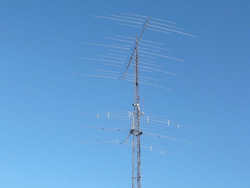
An increase in the number of wires reduces the characteristic impedance, approaching the ideal (of the indicated type of vibrator) - 37 ohms. Note that the quality should not be brought closer to the ideal, 50 Ohm does not need to be coordinated with the cable (in connection, RK - 50 is used). Great thing. Let's supplement the package of information with a simple fact, with horizontal polarization, the signal is added to the reflected Earth, giving an increase of 6 dB. So many disadvantages are shown by vertical polarization, they are used (it turned out interestingly with ground wires), they put up with it.
The device of HF antennas is reduced to a simple quarter-wave, half-wave vibrator. The latter are smaller in size, accept worse, the latter are easier to agree on. The masts are placed vertically, using spacers, stretch marks. Described a structure hung on a tree. Not everyone knows: there should be no interference at half a wavelength from the antenna. Applies to iron, reinforced concrete structures. Wait a moment to rejoice, at a frequency of 3.7 MHz the distance is ... 40 meters. The antenna reaches the eighth floor in height. Making a quarter-wave vibrator is not easy.
It is convenient to erect a tower to listen to the radio, we decided to recall the old way of catching long waves. Internal ferromagnetic antennas are found in Soviet-era receivers. Let's see if the designs are suitable for their intended purpose (catching broadcasting).

HF magnetic antenna
Let's say there is a need to accept frequencies from 3.7 to 7 MHz. Let's see if it is possible to design a magnetic antenna. Formed by a core of round, square, rectangular cross-section. The sizes are recalculated by the formula:
do = 2 √ pc / π;
do is the diameter of the round bar; h, c - height, width of the rectangular section.
Winding is not carried out for the entire length, in fact, you need to calculate how much to wind, choose the type of wire. Let's take an example of an old design textbook and try to calculate a HF antenna of frequencies from 3.7 to 7 MHz. Let us take the resistance of the input stage of the receiver 1000 Ohm (in practice, readers measure the input resistance of the receiver on their own), the parameter of the equivalent attenuation of the input circuit, at which the specified selectivity is achieved, der equal to 0.04.
The antenna we are designing is part of the resonant circuit. It turns out a cascade, endowed with a certain selectivity. How to solder, think for yourself, just follow the formulas. Carrying out the calculation will need to find the maximum, minimum capacity of the trimmer capacitor, using the formula: Cmax = K 2 Cmin + Co (K 2 - 1).
K is the coefficient of the sub-band, determined by the ratio of the maximum resonant frequency to the minimum. In our case, 7 / 3.7 = 1.9. Chosen from incomprehensible (according to the textbook) considerations, for example, given in the text, take equal to 30 pF. Let's not make a big mistake. Let Cmin = 10 pF, we find the upper limit of the adjustment:
Cmax = 3.58 x 10 + 30 (3.58 - 1) = 35.8 + 77.4 = 110 pF.
Rounded, of course, you can take a variable capacitor of a larger range. An example gives 10-365 pF. We calculate the required inductance of the circuit using the formula:
L = 2.53 x 10 4 (K 2 - 1) / (110 - 10) 7 2 = 13.47 μH.
The meaning of the formula is clear, let's add 7 - the upper limit of the range, expressed in MHz. Selecting the coil core. At the frequencies of the range at the core, the magnetic permeability is M = 100, we select the ferrite grade 100NN. We take a standard core 80 mm long and 8 mm in diameter. The ratio l / d = 80/8 = 10. From the reference books, we extract the effective value of the magnetic permeability md. It turns out 41.
We find the winding diameter D = 1.1 d = 8.8, the number of winding turns is determined by the formula:
W = √ (L / L1) D md mL pL qL;
we read the coefficients of the formula visually, using the graphs below. The figures will show the reference numbers used above. Look for the brand of ferrite, man does not live by bread alone. D is expressed in centimeters. The authors received: L1 = 0.001, mL = 0.38, pL = 0.9. qL is calculated using the formula:
qL = (d / D) 2 = (8 / 8.8) 2 = 0.826.
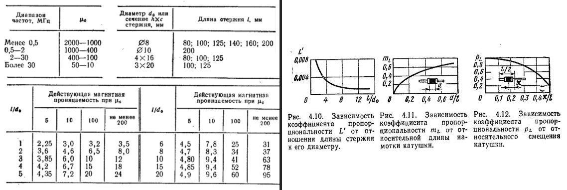
We substitute the numbers in the final expression for calculating the number of turns of the ferrite HF antenna, it turns out:
W = √ (13.47 / 0.001) x 0.88 x 41 x 0.38 x 0.9 x 0.826 = 373 turns.
The cascade must be connected to the first amplifier of the receiver, bypassing the input circuit. Let's say more, now we have calculated the means of selectivity in the 3.7-7 MHz range. In addition to the antenna, it turns on the input circuit of the receiver at the same time. Therefore, it will be necessary to calculate the inductance of communication with the amplifier, fulfilling the conditions for ensuring selectivity (we take typical values).
Lw = (der - d) Rin / 2 π fmin K 2 = (0.04 - 0.01) 1000/2 x 3.14 x 3.7 x 3.61 = 0.35 μH.
The transformation ratio will be m = √ 0.35 / 13.47 = 0.16. We find the number of turns of the communication coil: 373 x 0.16 = 60 turns. We wind the antenna with a PEV-1 wire with a diameter of 0.1 mm, we wind the coil with a PELSHO with a diameter of 0.12 mm.
Many people are probably interested in several questions. For example, the purpose of Co is the formulas for calculating a variable capacitor. The author shyly avoids the question, supposedly the initial capacity of the circuit. Hardworking readers will calculate the resonant frequencies of a parallel circuit in which an initial capacitance of 30 pF is soldered. We make a slight mistake by recommending placing a 30 pF trimmer next to the variable capacitor. The chain is being fine-tuned. Beginners are interested in the electrical circuit, which will include a homemade HF antenna ... The parallel circuit, the signal from which is removed by the transformer, is formed by wound coils. The core is common.
An independent HF antenna is ready. You will find this in a tourist receiver (models with a dynamo are popular today). Antennas in the HF range (and even more so in the CB) would be great if the structure was made in the form of a typical vibrator. Such designs are not used in portable technology. The simplest HF antennas take up a lot of space. The welcome is better. The purpose of the HF antenna is to improve the signal quality. In the apartment, loggia. We told how to make a miniature HF antenna. Use vibrators in the country, in the field, in the forest, in an open area. Material provided by the design guide. The book is full of mistakes, and the result seems to be bearable.
Even old textbooks are guilty of typos missed by editors. It concerns more than one branch of radio electronics.
Capital structures and balcony railing can be successfully used to fix the antenna in cases where the installation of this device on the roof of a building for some reason is not possible. Of course, the HF balcony antenna does not compare in efficiency with the basic one, but for many tasks its capabilities will be quite acceptable. In this article, we will consider in detail a number of issues related to the operation of such antennas, and we will learn how to make them ourselves.
catch the wave
Today, balcony antennas can often be seen on the facades of urban high-rise buildings. Almost all of them are designed for shortwave operation. With the help of such antennas, you can receive radio and television broadcasting signals, they also allow you to use radio stations for amateur or commercial (professional) radio communication. It should be noted that such devices are better at receiving radio signals than transmitting.
A home-made balcony HF antenna can always be fixed on the elements of the metal crate, since it has a low weight and small overall dimensions. Just first you need to make sure that the device receives the signal you need clearly enough. The fact is that due to the shielding properties of the building, the balcony antenna works effectively only in some directions, and if your balcony or loggia "looks" in the direction opposite to the signal source, it may be absolutely useless.
What radio waves are called short? This category includes electromagnetic radiation with a wavelength of 10 to 100 m... The frequency range of 3 - 30 MHz corresponds to these lengths. A remarkable property of these radio waves is their ability to reflect from the surface of the earth and the upper layers of the atmosphere, practically without losing power. Due to this, the wave, as it were, flows around the surface of the planet, which makes it possible to transmit signals over long distances.
If you notice a deterioration in the quality of communication, do not rush to take the antenna for scrap. Short-wave radio communications are very sensitive to many factors, among which the main ones are the time of day, weather conditions and the nature of solar activity. These factors affect the reception and transmission of a signal with a balcony antenna, which is inferior in its capabilities to the base antenna, especially noticeably. Another reason for signal level changes is interference. Waves from the same source reach the antenna along different paths, having, respectively, different durations. This is the reason for this phenomenon.
We design an antenna for the HF band
Those who have a hand in the morning instead of a toothbrush reaching for a soldering iron will probably be interested in how to make a homemade antenna from scrap materials. Primarily, we need a ferrite tube- shielding element for cables from monitors and keyboards. Some radio amateurs accidentally discovered that such tubes react with a reactive impedance of several hundred ohms to radio signals with a wavelength of just under 100 m.At the same time, a broadband transformer on such tubes demonstrates good frequency characteristics within the short-wave range. These properties of ferrite tubes will help us design an HV antenna for a balcony or loggia. To do this, you must follow the step-by-step instructions:
After being installed on the balcony, such a homemade HF antenna demonstrates good reception of signals with a frequency of 14 to 28 MHz.
Read about in our article. It also features other models such as floor and ceiling.
If you are wondering:, then you will find the answer to it on our website.
Setting up an amateur connection
On the territory of the Russian Federation, two radio frequency bands are open:
— range CB(Latin letters, the marking is read as "si-bi"), which is shortwave;
— PMR or LPD range, which is ultrashort wave.
They are called open because they can be used without special permission. However, there is one caveat: commercial use of the PMR band is not allowed.
CB waves (27 MHz) are able to bend around buildings, natural hills and woodlands. They are characterized by insignificant losses, so the antenna can be connected to the radio station using even cheap cable brands. Installation of base antennas for operation in the CB-band does not contradict the legislation.
The CB frequencies are characterized by a long-range transmission effect, which is caused by changes in solar activity or in the state of the magnetic field of our planet. It consists in the fact that a signal from a source located 10-15 thousand km away is received more clearly than from a station operating several kilometers away.
VHF signals (PMR and LPD) are transmitted at frequencies from 433 to 446 MHz. A mobile radio station operating on the LPD band is perfect for organizing communication, for example, between an office and a warehouse. Unlike the equipment "sharpened" for the CB-band, such stations support multi-channel communication and are equipped with very efficient built-in antennas. In addition, LPD stations can be used to organize communication within a building, and their signals can even reach the basement.
Tip: To listen to and communicate with other radio amateurs' radios, an AM / FM radio with a CB base antenna is the best choice. Such equipment will enable you to listen to both local stations and foreign radio broadcasting.


Our favorite HF Antennas. Shortwave antennas on the amateur bands, is and remains one of the hot topics in amateur radio. The beginner looks at which antenna to use and the aces of the ether look from time to time to see what new has appeared.
You don't have to stand still, but improve your results constantly, so we are going along this path, understanding and improving our antennas. You can even single out some radio amateurs into a separate group - Antenchiki.
Recently antennas and ready-made ones have become more affordable. But, even having bought such an antenna along with the installation, the owner, in our case, the radio amateur should have an idea.
In my mind, everything starts from the place where our antennas will be placed, then the antennas themselves. Of course, the choice of location is not given to everyone, but here we can win great, and how to choose, not everyone has such a flair, but there are such radio amateurs.
HF Antennas come first
Technically, it is problematic to compare the place on HF (on VHF it is simple and the measurements show a difference of four decibels). Let those who have such a choice of location be lucky. For the high-frequency ranges, the choice of antennas is larger and the dimensions are tolerable, but for the low-frequency ranges the choice of finished antennas is smaller. And it's understandable - not everyone can afford five yagi elements for a range of 80 meters. Here the field of work can be large if the radio amateur has such a field for placing antennas on the low frequency bands
There is such a book where there is a lot of information on antennas for the low frequency ranges.
HF and VHF amateur antennas
An antenna is a device participating in the process of transmitting electromagnetic energy from a power line to free space, and vice versa. Each antenna has an active element, such as a vibrator, and may also contain one or more passive elements. The active element of the antenna is a vibrator, as a rule. directly connected to the power line. The appearance of an alternating voltage on the vibrator is associated both with the propagation of a wave in the power line, and with the appearance of an electromagnetic field around the vibrator.
Ideal antenna for HAM communications per kv
What kind of antennas do we radio amateurs use? What do we need? Do we need an ideal antenna for meter bands. Say that there are no such people, and that nothing is perfect at all. Then close to perfect. What for? You ask. Anyone who wants to achieve results, to go forward, sooner or later will come to this issue. Let's take a look at how to understand the ideal antenna on the meter amateur bands.
Why exactly on the amateur meter meters, but because our correspondents are at different distances in different directions of the world. Let's add here the local conditions, where the antenna is located, and the conditions for the passage of radio waves at a given time on these frequencies. There will be many unknowns. What is the angle of radiation, what polarization will be maximum in a specific period of time with a specific correspondent (territory).
Yes, someone might get lucky. With place, choice of antennas, suspension height. So what should you do? To be always lucky. We need an antenna that at any time will have the best parameters for a given transmission of radio waves from any territory. More = We scan (rotate) the antenna in azimuth, this is good. This is the first condition. The second condition = we need to scan along the angle of radiation in the vertical plane.
If someone does not know, depending on the conditions of passage, the signal can come from different angles from the same correspondent. The third condition is polarization. Scanning or changing polarization from horizontal to vertical polarization and back, smoothly or stepwise. Having created and received these three conditions in one antenna, we get ideal antenna for radio amateur communication on short waves.
Ideal antenna
Ideal antenna so what it is. If we consider, for example, satellite dishes, then perhaps it becomes clearer, easier to understand. Here we take the size (diameter of the cymbal), this is a direct dependence on the gain. One satellite - for example, we took a 60cm antenna. diameter. The signal level at the receiver input will be small, and sometimes we will not see the picture. Let's take an antenna with a diameter of 130 cm. The level is normal, the picture is stable.
Now let's take an antenna with a diameter of 4 meters and what we can observe. Sometimes the picture disappears. Yes, there can be two reasons. This wind swung our 4-meter antenna and the signal disappeared. This satellite in orbit does not keep its coordinates stably. So it turns out, on the one hand, a 4-meter antenna is the best in terms of gain, on the other hand, it is not optimal, which means it is not ideal. In this case, the optimal antenna is 130 cm. In this case, why can't we call it ideal?
So it is on the meter radio amateur bands. Not always five yagi elements at 40 meters will be optimal for the 80 meter range. So they are not perfect. You can even give a few examples from practice. In his laboratory work, he made 3 elements for a 10-meter range. Passive elements are curved inwardly active. Then a three-band version of such an antenna will come into vogue under the well-known name.
I listened, twisted and, of course, made connections to this antenna, the first impression is wonderful. Then the weekend came, another contest. But when I switched on to 10-ku with this antenna, then silence, I think, yesterday the range thundered, but today there is no passage.
From time to time I switched on this range in order to listen, suddenly a passage would begin. At the next call to 10-ku, numerous radio amateur stations stunned me - it began. And then I immediately discover that the wrong antenna is connected. Instead of 3-elements, it turned out to be a pyramid for the 80-meter range. I switch to 3 elements - silence, signals are thundering to the pyramid. I went outside, examined 3 elements, maybe what happened, no, everything is fine.
Then I worked well at 28 megahertz, made a lot of connections to the pyramid for the 80-meter range. On Monday, Tuesday the same picture was observed, and only on Wednesday it seemed to fall into place. Silence on the pyramid, but thundering on the 3-elements. What is the difference? The difference in the angle of radiation.
In my pyramid there is radiation at 28 MHz. at an angle of 90 degrees, that is, to the zenith, and at a 3-element angle below 20 degrees. This practical example gives us something to think about. Another example, when I was in the zero area. I hear a call for the zero region on the 20-ke, I know that this friend has an antenna for several thousand dollars, that it is at a good height and the power amplifier is no less than a kilowatt. I call him, but he does not hear, or rather, he hears, but he cannot make out the call sign.
He twirled his expensive antenna, there was no sense, and out loud he said like that there is no passage today. Here at this frequency I hear - and you accept me. Yes, I accept. It turned out to be his neighbor and with only five watts and the antenna is such that I have already forgotten (perhaps, like a triangle for 80). We made a radio contact, and he was pleasantly surprised to know what kind of antenna and power the neighbor has. I don’t know how many meters or kilometers there are between them, but in that case the steep antenna was powerless.
Low frequency antennas
There was such laboratory work on both 40 and 80 meter bands. All this is in search of which antenna is better. And there is a moment where radio amateurs still have the opportunity to work on such an antenna so that it is optimal at any time, and therefore ideal. Partly radio amateurs use some points that should be incorporated into an ideal antenna.
The simplest is the azimuth adjustment. The second in terms of radiation angle - we put the same antennas on different masts, at different heights, or on one while commuting them into stacks. We get different angles of radiation. And also different antennas with different polarization, some have. But this is partly, not as a whole.
And some will say, why such an antenna. Ten kilowatts and the first place in your pocket. Yes, it's your choice. In this case, you are deceiving not only everyone, but first of all yourself. Or who has been using such an antenna on HF for a long time (there is on VHF), where the properties of an ideal antenna are laid down.
Our antennas
What is your antenna? 84 meters 27 centimeters and 28 meters of cable. Wow, but I have 32 centimeters, I need to shorten it, try like yours. This is our talk about antennas on the air. Here is a slightly different answer: and I have a cable of three meters, I sit near the window itself, and outside the window there is an antenna right away. Three is bad, you do 28, you know how great the antenna will work. But literally yesterday I heard, and the conversation was between two experienced radio amateurs. And the conversation was about some secret antenna, about secret dimensions.
kv antenna
For many radio amateurs, this topic has been, is and will be one of the most popular. Which antenna to choose, which one to buy. In either case, we need to mount it, install it, configure it, here we need some knowledge on antenna topics, here will help magazines books on antenna topics. So that, in the end, we understand something.
The radio amateur's antenna should be one of the first lines. Ksv is not an indicator and it is not necessary to chase after it in the first place. That an antenna with a SWR = 2 can perform much better than an antenna with SWR = 1. And the efficiency drops with increasing elements and much more.
kv antenna
 Log-periodic wire antenna for 40 meters. Everything is simple and effective. Several variants of sloper antennas for low-frequency ranges 40,80,160 meters. Scanned antenna RA6AA, tuning, parts used. In the magazine Radio amateur 1 1991. Read in full.
 Practice of tuning and mounting antennas. Raising the mast. Options for attaching antenna canvases to a tree. Adjustment using the GSS and a lamp voltmeter in the magazine Radio Amateur 2 1991. Read.
 In the seventh issue of 91 years of the magazine Radio Amateur RA6AEG talks about his M antenna.
All this information is primarily for those who already have the callsign of an amateur radio station, as well as for everyone else who has not yet come to HF.