Almost all LPD radio stations that have become widespread in recent years are equipped with shortened antennas, the efficiency of which often leaves much to be desired. Some of the radio stations of this range are structurally designed to work with another antenna (includes an antenna connector). The use of an external, more efficient antenna allows, during the operation of such radio stations, to increase the reception stability and range of radio communication in comparison with working with standard antennas. Below is a widely used design of such an antenna for the LPD range and a simple technology for its manufacture at home. When manufacturing this antenna, scarce materials are not required and if you have some skills in working with a soldering iron, this antenna module is manufactured within half an hour.
Structurally, the antenna is a block connector with a flange (1) on which a quarter-wave pin (2) and four "counterweights" (3) are mounted. The existing designs of similar antennas differ from each other in the type of connector used and the material of the pin and counterweights (as a rule, either of copper, which leads to a low rigidity of the entire structure, or of brass pins, which increases the weight of the structure and requires the use of powerful soldering irons when soldering). When developing this antenna, the focus was on reducing the weight of the structure and simplifying its manufacturing technology.
What do we need for manufacturing?
Firstly, a block connector BNC-socket with a flange for crimping the RG58 cable (see photo). You can, in principle, use a BNC socket threaded for soldering, but then you have to make the flange yourself and fix it on the connector using a nut with a lock washer. The use of the BNC connector is due to both the desire to reduce weight and the widespread availability of BNC cable connectors (in old computer networks on coaxial).
From the connector kit, we calmly throw out the tube for crimping (we will not need it).

The second "prerequisite" for our design is five regular bicycle spokes, which you can easily buy from any bike parts store. The bicycles have a diameter of 2 mm, good anti-corrosion coating and great rigidity, which is important for our "melted" design. We do not need the spoke nuts and can be attached to the crimp tube from the connector.

First of all, we press out the flange at the connector to enable its further painless heating during soldering. If you do not do this and warm up the connector entirely, the inner insert of the connector, made of plastic, will melt (unlike the good old CP-50, where this insert was made of fluoroplastic).

Screw four spokes into the threaded holes of the connector flange

We form "counterweights" from the spokes by bending them 45 degrees relative to the flange axis.

Armed with a soldering iron, solder and acid flux, we solder the threaded connections.

After the flange has cooled down, rinse it thoroughly, first with soap (to neutralize the acidic flux residues) and then alcohol (to degrease and remove the rosin residues).
After flushing, press the flange back onto the connector.

Let's put our "umbrella" aside for now and take care of the emitter pin. Here we need an insert from the connector and a fifth spoke.

We grind the end of the spoke so that it fits into the hole of the connector insert

Armed with a soldering iron and acid flux, first we tin the sharpened end of the spoke, and then we solder the spoke into the insert.

We wash the soldering point with soap and water, then degrease with alcohol. We take a piece of heat-shrinkable tube, put it on the place of soldering and warm it up.

Cut off the excess thermofit.

Insert the center pin into the connector.

We take another piece of heat-shrinkable tubing, put it on the connector so that it completely covers both the connector shank and the section of the spoke with the thermofit and warm it up.

Cut off the excess thermofit. Our pin is fixed in the connector.

We carry out the "cutting" of the knitting needles in accordance with the dimensions in the drawing. (The linear dimensions of the central emitter pin and "counterweights" are counted from the extreme point of the connector tube in the area of the output of the emitter pin.)
So we got the "hardware" with which you can already work.

If you plan to permanently place the antenna on the street, then you need to do a couple more strokes - to protect the ends of the spokes, where the anti-corrosion coating is broken. One way is to irradiate the ends of the needles with an acidic flux and then rinse them thoroughly (first with soap, then with alcohol).
The second option of protection can be wrapping the spokes with a heat-shrinkable cambric. In this case, to prevent moisture leakage into the connector, the cambric must be "put on" over the entire pin entirely from end to flange. On the end of the pin we put on a plastic "pipette" which excludes the direct ingress of moisture on the end of the pin and additionally serves as protection against "eye disease" during operation.

As a result of the work done, we received an antenna module with a low weight and very good rigidity, which is very important for the stability of the geometric characteristics of the antenna, and therefore its electrical characteristics.

To connect to the radio station, we just need to cut the cable. At one end of the cable we cut the pin-BNC connector, on the other - the connector for connecting to the LPD radio station (most likely this is the pin-SMA for such stations as Midland GXT-400, GXT-500, YAESU VX-5, VX-6, VX7 etc. or SMA female for JJ-Connect family of radios with antenna connector). At the second end of the cable, you can also cut the pin-BNC connector and connect the station through an adapter. The widespread RG58 can be used as a cable with a short length (up to about 3-4 m). At such lengths, the loss in it can be neglected in favor of its flexibility. If a greater distance of the antenna from the radio station is required, then it is advisable to look for a cable with less losses.

Having cut the cable and connect it to our "umbrella". The issue of fixing our antenna either on the radio itself, or on the car, or on the balcony is already "another topic" with many options and we will not consider it here

In most cases, when it comes to antennas, people imagine large "dishes" that are installed outside the window or on the roof of the house. However, it should be understood that this is far from the case. The fact is that the size of the antenna depends on what frequency and wavelength it will catch. Naturally, if you want to catch a satellite signal in order to broadcast several dozen TV channels, then you will need a large antenna. But you don't always need such a signal. This is why it is worth considering such a thing as a 433 MHz antenna. This device is very different from the antennas you are used to seeing on windows and roofs. It is very small and, as you can see from the name, does not receive the longest signal waves. Why would such waves be useful? Most people ignore them, but if you love filling your home with various remote-controlled items, then you will definitely need more than one 433 MHz antenna. If you learn how to use their properties, you can create such things in your apartment as a radio socket or even a remote-controlled pet feeder. Interested? Then read the article below, and you will find out what this antenna is, how to use it, where to buy it, and most importantly, how to make it yourself if you do not want to spend money on a purchase.
What is this antenna?
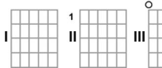
So, first of all, you need to understand what constitutes a 433 MHz antenna. As you might have already understood, this is a device that allows you to tune a certain device to a specific frequency in order to then interact with it. By installing an antenna in a specific device, you can then send it a signal at a specific frequency to activate and control that device. This is a very useful feature in any home, as you can greatly simplify many processes. However, not everyone can do something like this - you need to be well versed in this area in order to tune the devices to the desired frequency. But if you set a goal for yourself, then you can definitely achieve it. You just have to try hard, and it's worth starting by studying this particular antenna, since it is one of the most important elements. You should definitely know that the 433 MHz antenna comes in three types: whip, coiled, and PCB etched. How do they differ? Which one is better to choose? This is what will be discussed further. You will have to find out what each of these antennas is and understand which one is best for your specific purpose.
Whip antennas

How can you have a 433 MHz antenna at your disposal? It is quite simple to make it with your own hands, but you can also purchase a ready-made one, which will cost you a little more, but save a little time. In any case, you first need to decide which type you want to get. And the first type that will be discussed is a whip antenna. Its main advantage is that it has the best technical characteristics in comparison with other types. That is why almost always people make a choice in its favor. Moreover, it is much easier to do it yourself. So in general, this is the best 433 MHz antenna, do it yourself or bought in a store. However, you shouldn't think that she's perfect. If this were the case, there would simply be no need for other species. That is why it is necessary to separately consider the disadvantages that this type of antenna has, so that you are aware of all the features before making a purchase decision.
Disadvantages of whip antennas

The first disadvantage of 433 MHz whip directional antennas is their exposure to environmental influences. The problem is the very strong reflection and interference that occurs if you try to use the antenna indoors. Thus, it is more suitable for portable devices, and not for household appliances, since in houses, due to the small amount of space, obstacles in the form of furniture and walls, the signal can be distorted, lost and not reach the target device. So, first of all, you should think about the purpose for which you are going to use the antenna, and then make a decision about buying it. However, this is not the only drawback of whip antennas, which initially may have seemed ideal. It turns out that the pin in this antenna should be practically (or completely) parallel to the ground plate, on which the structure itself is located. As you can easily understand, this is very difficult to implement in small household appliances. Therefore, you may already have figured out that 433 MHz whip directional antennas are best suited for various portable devices of a more or less large size or those on which the antenna can be mounted outside. It is not recommended to use such antennas at home. But what then replace them? As far as you remember, there are two more types of such antennas, so it's time to pay attention to them.
Spiral antennas

The easiest way to give you a homemade whip antenna for 433 MHz, however, as you may have noticed above, it is not ideal. Therefore, it is worth paying attention to other types, for example, a spiral antenna. How does it differ from a pin? Firstly, it also has good technical characteristics, so in this regard, you can use both the first and the second type with complete peace of mind. What about interference? It turns out that they are also present in enclosed spaces for a spiral antenna, and sometimes they are even stronger than for whip antennas. Therefore, it remains to look at the last parameter - compactness. As you remember, whip antennas, due to the design feature, must either be placed on the device body or inside it, but at the same time there must be quite a lot of free space inside the device, which is difficult to achieve when it comes to small household appliances for home use. And according to this parameter, the spiral antenna bypasses the whip antenna, because it is extremely compact and will allow you to make almost every device in your home radio-controlled. Naturally, a homemade 433 MHz directional antenna made this way will take you much longer, but if you are going to buy an antenna then you should definitely look at the spiral versions as they can come in handy and help a lot.
Antenna on board
If you need a quality compact 433 MHz collinear antenna, then you should definitely pay attention to this type, that is, the antennas that are embedded in the board. This means that this type is impossible (or very difficult) to do with your own hands, so they will be considered exclusively purchased. What are their advantages over the two types described above? First of all, they have good characteristics. Of course, not as impressive as the previous two options, but good enough for everyday use. Their main advantage is their compactness - such antennas can be placed in absolutely any device. But, as mentioned above, their main drawback is that a do-it-yourself dual-band 144-433 MHz antenna on a board is something fantastic. That is why this option will not be considered further for the reason that the rest of the article will be devoted to creating an antenna with your own hands. How difficult is it to do? What is needed for this? You will learn about all this further.
Necessary calculations

But if you decide to make an antenna with your own hands, then you will need a lot of theoretical knowledge on this topic. The fact is that any deviation in the manufacturing process will not allow you to tune the antenna to receive a specific frequency. Therefore, everything must be done very accurately, so it is always recommended to start with calculations. It's not that hard to make them because all you need to calculate is the wavelength. Perhaps you are good at physics, so it will be much easier for you, since you will understand what is at stake. But even if physics isn't your greatest strength, you don't need to understand what each variable means in order to make the necessary calculations. So how is the 433 MHz antenna length calculated? The most basic equation you need to know is the one that will allow you to calculate the antenna length you need. To do this, you need to first since the antenna length is one quarter of the wavelength. Those people who understand physics can themselves calculate the required wavelength for a specific frequency: in this case, it is 433 MHz. What needs to be done? You need to take an indicator of the speed of light, which is constant, and then divide it by the frequency you need. As a result, it turns out that the wavelength for this frequency is about 69 centimeters, but with such a detailed setting it is better to use more accurate values, so it is worth keeping at least two decimal places, that is, the final result is 69.14 centimeters. Now you need to divide the resulting value by four, and you get a quarter of the wavelength, that is, 17.3 centimeters. That should be your 433 MHz J-antenna or whatever you want to use. Remember that regardless of the type, the antenna length must remain the same.
Using the received data
Now you need to use the data you received in practice. The 144-433 MHz antenna can be made in different ways, however the practical application of the theoretical knowledge should always be the same. What is it about? First, you should always take a wire a few centimeters longer than the desired antenna length. Why? The fact is that in theory everything turns out quite accurately, but in practice everything will not always work as you plan. Therefore, you should always have some margin in case something goes wrong or the signal will not be picked up at the frequency you wanted. You can always easily bite off the wire at a specific spot once you've determined the length you need. Secondly, you should always remember that the length is measured from where the wire comes out of the base. Thus, the resulting 17 centimeters should be measured from the base of your antenna. More often than not, you will need to use a slightly longer wire as you will need to solder your antenna. The 433 MHz whip antenna will work better the more rods you use, so make sure that each one is the same length.
Preparation of materials

So, the theory is over, it's time to get into practice. To do this, you will need to take everything you need to create your own antenna. First of all, these are wires or rods that will make up the main receiving part of your antenna. Secondly, you will need a base for your antenna. It is desirable that there are several holes in it that you can use to attach the pins. If these holes are not there, you will have to either drill holes or solder directly to straight metal, which is not very convenient and will not allow you to correctly calculate the length in advance. Therefore, use a pre-drilled base. Naturally, you will need other things, such as, for example, a soldering iron, but everyone knows about this, so it makes no sense to list all such items.
Execution of works
First of all, you need to prepare the material for further work. To do this, you need to clean, tin and flux all the pins. After that, you need to cut the pins to the required length, but do not forget to leave a little length in order to then correct the finished result. Then you need to start soldering - each of the pins must be soldered on the back of the antenna, and then take another one that will be attached to the antenna. Its length does not matter anymore, since it will act as a holder and will not be responsible for receiving the signal. It also needs to be soldered, after which you can already admire the result of your work.
Final steps

Well, your antenna is already ready to use. You just have to take the final steps. Cut off excess pins to ensure perfect signal reception. If you have heat shrink, use it. And remember - this is just one example of a homemade antenna. You can make a helical antenna as well, and your whip antenna might look completely different. However, the calculations for obtaining the antenna length are relevant in any case, and the steps for creating an antenna with your own hands will also differ only in details.
Experimenting with terrain-dependent communication range and having made a number of conclusions for myself, I focused on working on the network of Internet relays LPDnet.
It is also worth mentioning the first experience of working through crossband. One afternoon, I unsuccessfully called Kolya RN3KK on 433.500 (before that we made contacts at a pre-agreed time) and Sergey RN3KU answered me. At that time, he had a Yaesu FT-8800R and he could easily listen to two frequencies at once. Word for word and he invited me to do crossband 433.500<-->145.500 so that I can call RN3KK there. There were already real radio amateurs, of whom you can rarely meet at 433 to this day. In general, having called RN3KK on 145.500 several times, I did not hear him, but other radio amateurs answered. After telling who I am, where I am from and where I work, I was told that Kolya RN3KK here (145.500) has not been on FM for a very long time, but works on SSB on 144.300. Communication with Kolya RN3KK that day failed, but I met Sergey RN3KU, who later made a crossband for me several times to the frequency of the local Echolinka. For which many thanks to him!
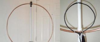
In LPDnet, it was possible to work without problems only from the balcony, tk. there were the best reception / transmission rates. Climbing the site LPDnet, I found many descriptions on the manufacture of antennas, but one attracted attention - the Kharchenko antenna.
And it attracted, first of all, by the simplicity of manufacture (made from one piece of wire), has a pronounced directivity (when using a reflector) and a good gain (8-10 dB).
There were no special problems in the manufacture of the antenna itself, except that there was nothing to make a reflector from. The antenna web was first made of copper wire with a cross section of 1.5 mm 2, but later it began to be made of a wire with a cross section of 2-2.5 mm 2, since it is more rigid and does not bend under light loads. Also, the thickness of the vibrator material affects the broadband.


I hung the antenna on the balcony window, since it looks strictly in the direction of one of the LPD links. Among other things, the window plays the role of a rotary device - opening and closing it, you can change the direction for receiving / transmitting. Perhaps, the power supply to the antenna is not quite correct - in the works of Kharchenko and in the figure above, the feeder is fed along one of the antenna's "arms", while mine is from below and immediately to the center. Distortion of the radiation pattern and high SWR values are quite probable, but more on that later.
At that time, the main problem I had was connecting this antenna to the radio station. The cable is simply soldered to the antenna, but it is attached to the radio station using the SMA connector (in my case). I described how to solve this issue in an article titled " Crimping method for RG-8X cable with SMA connector for RG-58 cable ". As a result, my connection looked like this:


In general, the reception / transmission situation has changed dramatically for the better - I sometimes accepted the link up to 9 ++, and opened it with 0.5W. Before installing this antenna, I did not hear Andrei RL3QAM, when he, being at the threshold of the building where the link was installed, was broadcasting from his portable with an elastic band. On that day, I was able to talk to him on a live channel with 100% intelligibility. Nevertheless, there were problems with soldering the cable to the antenna web - over time, the contact departed. This was solved by better soldering and careful fastening of the cable to the window frame, so as not to create a load during the opening / closing of the window. There was also a problem at the junction of the RG-8X cable with the RG-58 - the transition from a thick cable to a thin one. Sometimes there was poor contact, and with frequent unscrewing / winding of the SMA connector, the contact in the connector itself deteriorated, up to the disconnection of the cable from the connector at the moment of unscrewing. All this negatively affected the reception / transmission.
The solution came in the form of an SMA (male) -BNC (female) adapter. The problem was to get it at that time, but now there is on Ali.


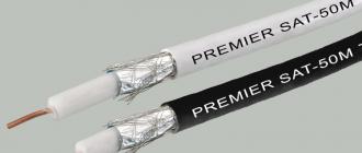
Bite off a piece from the RG-58 and discard. The remaining cable is stripped and crimped with a BNC connector (Ali has a straight or angled one).


BNC connectors are different - for different cables, with different types of fastening (crimping, soldering, for a screw), straight and angled. Crimping the cable with a screw-fastened connector does not leave much difficulty, but, in any case, soldering will always be safer and better. But for experiments it will do just that.


Straight connectors are crimped in the same way:

As a result, everything looks much prettier and more reliable:

After using such an adapter, the problems with poor contact at the place where the cable was attached to the station connector disappeared. There are also various other adapters such as SMA-PL.

The main problem with them is their availability in stores and their prices. The original ones from Yaesu are much more expensive than such unnamed ones.
The next problem to be solved was power problem... It consisted in the fact that my portables were powered by rechargeable batteries. Batteries tend to run out and charge the batteries takes time, during which the radio must be off. It was 10-14 hours. Those. during this time, I had no opportunity to receive or transmit anything. Noticing on the VX-177 the signature to the charging connector as "EXT DC", which means "external power", I thought about this very external power supply, more precisely about the source. Native charging was only suitable for charging the battery, although in the receive mode the station could also work from charging, but they wrote on the Internet that charging should not be used for other purposes. Someone tried and the charges died. And then - listening is one thing, and transmitting and listening is another. On the Midlands 500, work on anything other than batteries was not provided, except that charging was possible not through a glass, but through a microphone jack. They wrote about it, but that's another story.
After talking on this topic with Kolya RN3KK and Andrey RL3QAM, I came to the conclusion that the simplest power source is a converted power supply unit from a computer. I just had one unnecessarily. After a visit to RN3KK, I had a disassembled power supply unit with a large number of bitten out wires, a jumper to turn on the power supply unit and marked soldering points. Having soldered + and -, I started experimenting.

I decided to connect to the station not through the charging connector, but directly to the battery terminals. There was simply no suitable plug at hand. To do this, I first determined where + and where - at the battery, and then connected the power with the help of "crocodiles".


The station turned on and showed a voltage of 12V. Well, sometimes 11.9V.


Everything would be fine, but when receiving signals from the speaker, in addition to the speech of the correspondents, there was some kind of buzzing, buzzing, and it made intelligibility very difficult. In addition, the BP itself emitted a crackling sound.
On the advice of Andrey RL3QAM, fortunately, he had experience in reworking computer power supplies to power his links, two capacitors and one KREN stabilizer were bought (I don't remember the marking further, but you can't see it in the photo ...).

After a visit to Andrey RL3QAM, I had a power supply unit with soldered air ducts to filter out interference from the power supply unit itself and a stabilizer to reduce the output voltage to 9V (just in case). This situation was radically corrected - the buzz and crackle in the station dynamics disappeared, but the crackle in the power supply unit itself did not disappear. In any case, thanks to Andrey for his help!
I didn’t power the VX-177 with this power supply for very long. a little later, the option of using another computer power supply appeared, but in any case, the use of a power supply is much more convenient than batteries that need to be charged. And later, somewhere I got hold of an ancient computer power supply unit, which, after alteration, which consisted of soldering a jumper, installing a switch on, biting out all unnecessary wires and soldering wires of the required length to + and- 12V, worked generally silently (only the fan was spinning) and gave 10-11V. I also later used the connection of the station through the corresponding connector by means of a plug. For this power supply unit, we should thank Kolya RN3KK, to whom the old power supply unit was given for experiments. Kolya later reported that the crackling BP was like a time bomb.

But the experiments with nutrition did not end there. Somehow I got a pair of used lead-acid batteries from the UPS. The accumulators were CSB GP 1272 with a capacity of 7.2 Ah, with a voltage of 12V. The idea to try such a battery as a power source came at a time when the lights were turned off for a long time. Yes, there is a native rechargeable battery, but with intensive use it will fail faster, and a new one is much more expensive than CSB GP 1272 or similar. So, why not, being at home, but without electricity (temporarily) not use such a battery? In general, the experiment was successful - the station was powered without any problems from such a battery, and at 5W of power everything worked fine, there was no strong voltage drop. True, the batteries were already worn out, and they were enough for 30 minutes. I bought a couple of these new batteries and a 220V charger for them. Later, these batteries were very useful to me, but at that time it looked like this:

The downside was that the battery could not be discharged below 10.8V, otherwise the lead plates are already being destroyed. In order to know the current voltage, one had to either look at the built-in voltmeter VX-177 and not see any other information on the display, or, as was done, connect a separate voltmeter and always see the current voltage level. True, the battery in the multimeter had to be changed quite often.
As a summary, I will note the fact that, somehow, without noticing it myself, I tried to make a base station out of a portable ... and it worked. External antenna, power supply from 220V, tangent….
Two cars are a company, and three are already a column. And the more participants, the more difficult it is to coordinate. The issue of prompt and reliable communication is acute. It would seem that the simplest and most obvious option is cellular communication. But it has several serious drawbacks: dependence on the availability of a cell tower, the need to wait for a connection to be established, the operator's services are not free.
We quickly and decisively get rid of the cellular operator, move from digital to analog, go to the legally permitted frequency range - and we get a civilian radio station (CB, LPD or PMR) in front of us. We are no longer dependent on the infrastructure of an intermediary operator, we can quickly communicate with each other by pressing one button, we only pay for batteries or battery charging. But here, alas, not without flaws.
There is such a thing as a stable communication range. It consists of the power of the transmitter, the selectivity and sensitivity of the receiver, the efficiency of the transmitting and receiving antennas, the level of electromagnetic interference, obstacles between the receiver and the transmitter, and so on. That is, for maximum communication quality, we need to take a powerful transmitter and a high-quality receiver, install an antenna with a high gain, find a frequency free from interference and try to eliminate all obstacles. So smoothly and unobtrusively we came to a set of equipment for a base radio amateur station, with which you can communicate for tens, hundreds, or even thousands of kilometers)

Our task is more modest: as a rule, when moving in a convoy, the communication range is not particularly long, several kilometers should be enough (provided that the crews are disciplined and do not strive to stretch out and get confused in all directions). The "entry threshold" is also important - it is obvious that the CB (27 MHz) range is optimal for land mobile radio communications, but in order to communicate in this range, you will have to install a rather long antenna on the car, which not everyone is ready to go for - there are a lot of problems. On LPD and PMR bands, antenna length requirements are much lower. Therefore, the most logical option is to buy portable transceivers of the LPD / PMR range (433/446 MHz), that is, exactly what is meant by the majority when the word "walkie-talkie" is used.
There are a huge number of models included in the LPD / PMR bands, as a rule, most of them come with a set of "two radios". The legislation provides for limiting the maximum transmitter power for LPD (433MHz) - 0.01W, for PMR (446MHz) - 0.5W. The use of external and directional antennas is prohibited. In fact, you can easily purchase an LPD walkie-talkie with a power of, for example, 4 watts - and where does the radio frequency center look?))
Since we don't get paid for the reviews, we collected the radios as best they could - at the cadabra.

The following company picked up:

Midland GXT-1050
PMR:
Voxtel MR-190

Motorola T5622
* apparently a subtle hint that the walkie-talkie can be "opened" to high power

Cobra MT600-2
VHF / UHF
Baofeng UV-5R
| Standard | VHF / UHF |
| Frequency range | 136-174 MHz, 400-480 MHz |
| Transmitter power | 4 watts |
| Switching transmitter power | there is |
| Modulation type | FM |
| Sensitivity | 0.2 μV (12dB SINAD) |
| Encoding support | CTCSS, DCS, DTMF |
| Number of codes | 154 |
| Antenna | removable |
| Working hours | 12 h |
| Number of batteries | 1 |
| Format | your own |
| Battery type | Li-Ion |
| Battery capacity | 1800 mAh |
| Connecting the charger | there is |
| Peculiarities | charge indicator, power saving mode |
| Dimensions (WxHxT) | 58x110x32 mm |
| Working temperature | -20 - 60 ° C |
| Average price: | RUB 2,290 for one radio |
This walkie-talkie covers a much wider range than conventional LPD / PMR. It is possible to work for reception and transmission from 400 to 480 Mhz. Also, there is a second range (the so-called "two") 136-174Mhz, which allows us to regard this transceiver as an amateur radio device.
There was an opportunity to test it with standard and extended antennas, so the tables will periodically contain either one or both options.
Separately, out of the set (because the connection with her is such that it is easier to shout at each other at the window) CB-portable
Midland Alan 42
We immediately decided that we would conduct tests exclusively while in the car, that is, we deliberately complicated the conditions. Everything had to be as close to reality as possible, because you will not constantly stop at the side of the road and climb a hillock to transmit any information to a distant subscriber.
The terrain for testing was chosen of two types: a city with dense buildings and a suburban highway. At the same time, two series of tests were carried out in each location: in the presence of line of sight and in the presence of obstacles between two subscribers. For the test, two first-generation Kia Sportage cars were taken, on which sets of automotive CB radio communication were installed - through it we maintained constant communication between the crews.


The tests themselves looked like this: both cars stop at the same point (A), one car remains in place, the second drives off a given distance (measured by a GPS navigator in a straight line) and stops. We turn on the first set of walkie-talkies, the first car calls the second, then vice versa, we write the assessment on a subjective ten-point scale, turn off the walkie-talkies, take the next set, and so on, until we check everything. After that, the first car continues to stand in the same place, and the second goes on, and everything starts all over again.
And so, the first location is "city":

The long and straight Bogatyrsky Avenue came in handy. A straight line connection was measured along it. The results were recorded from the point of view of the subscriber in this particular vehicle. That is, there were situations when a subscriber in car # 1 did not receive a subscriber from car # 2 at all, while in the opposite direction the connection was quite good. Perhaps this is due to the presence of e / m interference at different points of the location, which blocked the reception, but did not interfere with the transmission. Here are the results:
City, line of sight
| Midland GXT-1050 | Voxtel MR-190 | Motorola T5622 | Cobra MT600-2 | Baofeng UV-5R | |
|---|---|---|---|---|---|
| 500m | 10 | 8 noisy | Signal 8, intelligibility 2, poor modulation | Reception 6, noisy, transmission 0-1. | 10 |
| 800m | Receive 8, Gear 6 | 4 | Receive 1, Gear 0-1 | 0 | 9, with standard antenna 8 |
| 1100m | Receive 4, Transmit 3 (on another channel 6) | 3 | Roger beep 5 intelligibility 0 | Get 2, Gear 0 | 8, with standard antenna 7 |
| 1660m | 6 | 1 | Roger beep 3 intelligibility 0 | Get 1, Gear 0 | 7, with standard antenna 6 |
| 2050m | 2 with noise (with no noise suppression) | 1 | Roger beep 1, intelligibility 0 | 0 | 5, with standard antenna 3 |
| 2600m | 0 | 0 | 0 | 0 | 5, with standard antenna 7 |
| 3200m | 0-1 | 0 | 0 | 0 | Receive 0, Gear 7 |
City, with obstacles (houses, urban areas) Either that day we were unlucky, or always so, but the LPD range turned out to be totally crap - everywhere there was some interference, builders, security guards, on almost every channel either something was making noise, or someone was talking. The PMR range, despite its only 8 channels, was clean - a minimum of interference and extraneous conversations. I was very surprised by CB - after 2 km it became extremely difficult to communicate. However, this is natural for the city, since at 27 MHz, any urban technogen is strongly interfered with by interference, which at 433-446 MHz remains unnoticed.

1. Baofeng became the leader with a large margin - this is not surprising, with 4 watts of power and an effective antenna it is difficult to compete with him. At one point, the standard antenna began to work even better than the elongated antenna - the possibly more effective antenna, due to its sensitivity, was able to "catch" some kind of interference that the short one "did not hear".
2. The Midland GXT-1050 was in second place in terms of range.
3. Unexpectedly, the third place was taken by Voxtel MR-190.
4. Cobra MT600-2 - one of the walkie-talkies in this set turned out to be defective and refused to work normally in transmission, we had to evaluate the connection in one-way mode.
5. Motorola T5622 is an amazing walkie-talkie. It would seem that a sufficiently powerful signal, which confidently opened the noise reduction up to 2 km in a straight line. But the modulation is so disgusting that it is completely impossible to make out the words. Feeling that the person is talking with a sealed mouth. Therefore, there are two scores in the cell - voice intelligibility scores and Roger Beep intelligibility scores (end-of-transmission signal, sent by the radio automatically when the button is released). Honorable last place.
Midland Alan 42, competing outside of the standings, dropped out of the competition already on the 500m. The fact is that even at such a ridiculous distance, I had to get out of the car into the street - when transferring from the passenger compartment, he could not even open the noise reduction from another subscriber. He worked on the transfer by 1 point, after which it became clear that there was no point in wasting time on his further testing. The axiom was again confirmed that it makes sense to work in the CB range only if there is a sufficiently serious set of equipment. There is no place for portable laptops.
We move to the second location - "suburban highway"

Straight track In terms of seating, the picture is the same as in the city - Baofeng, Midland GXT, Voxtel, Cobra, Motorola. In the test with irregularities at the 2000m point, Baofeng unexpectedly gave way to Midland - most likely we stumbled upon some kind of interference at this frequency, perhaps it was worth trying other channels, and the picture would have changed.
The test "in a straight line" had to be stopped at 2000m due to the fact that a flat asphalt straight line ended there, and then there were turns. Therefore, it was not possible to establish the maximum communication range in a straight line outside the city. But the purpose of our research was not so much to identify the most "long-range" radio, but to determine at what distance, in general, it is possible to communicate comfortably while driving. By the way, the CB outside the city worked quite well at all the above distances.

The conclusion is this: when using the usual popular PMR / LPD, sold in sets, when driving both in the city and outside the city - you should not separate further than ~ 1.5 km - any uneven terrain, turn or other obstacle, and the communication range immediately drops very much. And the optimistic range figures stated in the brochures should be boldly divided by 2.

Many thanks to the cadabre teammates @Turbocat, @BeeRMaN, @Michspar and @Cooleroff for the radios provided. And also @Michspar and @Cooleroff special thanks for their help with the tests.
You can install a walkie-talkie in a car for various reasons. This could be a future car ride with friends with friends, or even a passion for eavesdropping in the car. But basically, such a device is installed either by taxi drivers or truckers. Whatever the reason, a walkie-talkie antenna must be installed for the unit to function properly.
Such an installation may seem simple only at first glance. In fact, there are several nuances that need to be considered when choosing, manufacturing and installing an antenna.
Types of external transceiver devices
There are two types of antennas for walkie-talkies in the car:
- mortise:
- with a magnetic base.
They are not fundamentally different. The main difference is that the cut-in antenna for the walkie-talkie is stationary, and with a magnetic base it is removable, it can be removed or rearranged to another place.
Flush antennas
From the name it is clear that they are attached in one place. Therefore, before installing this device, you need to carefully think about where to mount it, so as not to interfere, and the reception was good. You should also take into account the fact: the antenna for the walkie-talkie in the car must be attached to the supporting body. If we neglect this postulate and install it, for example, on the hood or fender, that is, on a false mass, the efficiency of the device is lost by 30-40%. Some car enthusiasts are trying to improve such a system and try to throw a lot of additional wires to the body. But all the same, the desired effect cannot be achieved in this way. Although sometimes it works, it is extremely rare. As a rule, such an antenna for a walkie-talkie still works quite well for reception, but the transmission with the help of such a device is very nasty.
Height will be an important factor in installation. The higher the device is installed, the more efficient its operation will be. For example, if you mount the antenna in the bumper of a car, the transmission and reception range is halved.
It is optimal to install the antenna in the middle of the roof. Some craftsmen are convinced that it can be installed with equal success on a bracket in the corner of the roof. But there are some points that need to be taken into account for a reasonable installation. If the installation of a walkie-talkie is needed only for city driving, then the option of mounting on a bracket is completely suitable. This will not affect the operation of the device due to the fact that the directional effect will not be created in the city due to additional reflections. If this unit is installed for long journeys on the highway, then the installation of an antenna for car radios in the corner of the roof will be impractical.

Installing a flush-mount antenna
When installing the antenna in the roof, it is imperative to reinforce the joint with an additional metal plate. This is necessary primarily for greater bond strength.
The web itself and the extension coil should be as far away as possible from all vertical metal planes that are parallel to the base of the antenna. The minimum distance between them should be 50 cm. If this factor is neglected, then the device will not work properly due to the high reactivity of the space. This nuance should be taken into account when installing an antenna for car walkie-talkies, in trucks as well.

Antennas with a magnetic base
An antenna with a magnetic base, or, as the people call it, "magnetka", can be used on any car. But there are several points to be observed when installing it.
- For more efficient operation and correct adjustment, this device should also be installed on a monocoque body.
- In no case should you change the length of the cable from the antenna. This will lead to the impossibility of adjustment or affect the deterioration of the device's performance.
- It is not recommended to roll the cable into a coil, it can also adversely affect the operation of the device. If the cable is longer than necessary, then it just needs to be carefully laid through the cabin.
- The position of the antenna on the roof can be arbitrary. This view is not very picky about location. But if there is a need to dismantle the device, then the next time you have to use it again, you should try to put the antenna in the same place.

Antenna for a walkie-talkie with your own hands
The easiest way to solve this kind of car upgrade is to buy an antenna. But it can be made independently. To do this, you can follow the step-by-step instructions.
- Take a simple whip antenna from the radio. It only needs a foundation.
- Buy knitting metal needles with a diameter of 3-4 mm.
- Make an extension coil. It should be 10 mm on the mandrel. For its correct operation, you need to wind 44 turns of PEV 0.41 wire.
- Next, you need to solder the ends of the coil to the brass bushings. This will ensure good contact and provide additional structural strength.
- After that, spokes must be connected to the bushings from each end. It is important that both needles are of equal length.
- Next, the SWR meter is tuned and the spokes and coil are fitted.
- Then the direct installation of the antenna for car walkie-talkies is carried out.
- Open the ceiling.
- Unscrew the standard antenna, unscrew 2 screws, remove the active amplifier board and carefully solder it.
- Solder a 50-ohm coaxial cable in place. It is important to keep the order of life, mass to mass.
- Seal all connections.
- Lead the coaxial wire under the casing, rug and lead to the radio.
- Attach the antenna in place.
If all steps of the algorithm were done correctly, then the antenna for the walkie-talkie was made by hand. You can proceed to the next stage - setting. But, according to experts, this is a rather complicated and delicate process. This is due to many aspects: you need to carefully be able to solder, coil winding is also not easy to do correctly. As a conclusion: a home-made device can only be made by a sufficiently trained amateur. Otherwise, a good antenna for a walkie-talkie will not work in this way.

Antenna tuning
If the antenna is installed correctly and correctly, then it only needs a little adjustment. But many motorists are skeptical about this process, thinking that this element of the communication system is not of particular importance for the operation of the entire apparatus. And they are deeply mistaken. Not only the reception signal, but also the operation of the device itself depends on how correctly the antenna for the radio is installed and the device is tuned. Moreover, if you incorrectly configure the walkie-talkie, you can disable not only the transistors of the output stage, but also ruin the device itself.

Step-by-step setup instructions
Tuning the antenna of the walkie-talkie should be done according to the following algorithm:
- For correct tuning, you must have a device such as a SWR meter.
- The tuning process must be done away from structures made of metal, concrete or wood. It is desirable that the trees be placed no closer than 15-20 m.
- It is highly advisable to stop the vehicle on a clean, level and dry surface.
- Antenna alignment can also be affected by other vehicles with radio antennas in the vicinity. Next, you need to install the SWR meter according to the instructions, that is, between the radio itself and the antenna. In this case, the amplifier cannot be used.
- Measurements with the device must be made on several different channels and at different points. It is advisable to carry out this procedure in different meshes. This will allow you to see the real picture of the setup.
- The next step is very important: you should find the minimum SWR indicator, ideally the indicator should be equal to 1, it is advisable to write down where it is located. If it is located at a frequency lower than the indicated one, then this means that the antenna needs to be shortened. Accordingly, if higher, you need to lengthen.
- The next step is to shorten or lengthen the antenna, depending on the SWR instrument. Extending or shortening is the process of adding or, conversely, unwinding turns from the matching coil, and not shortening the antenna with wire cutters.
- After that, you need to look again at the SWR meter readings. Repeat the procedure until the desired result is achieved. Sometimes in some models it is not possible to achieve the ideal indicator, but this is not scary. If the indicator deviates, for example, up to 1.5, the losses will be equal to 5%. The radio will work quite normally even with an indicator of 3. If an amplifier is installed in the system, it must be taken into account that the minimum indicator should not exceed 2.
If all steps of the algorithm are completed correctly, the antenna for the walkie-talkie in the car will serve excellently.