Electronic integrated circuits are a branch of our science and technology, the possibilities of which are far from being exhausted. Apparently, these are the sprouts of that very artificial intelligence, about which so much has already been said. Moreover, if our natural intelligence is built on elements - neurons - which can be called electronic-chemical, then integrated circuits created by human hands do not occur in nature. This is a pure invention of the human mind. It was obtained as a result of a long work on improving the most ordinary electrical appliances that people needed immediately after the discovery of electricity - switches, resistors, capacitors, semiconductor devices. Improvement went both in the direction of complicating the schemes, and in the desire to fit a large number of elements in a limited area or in a limited volume. And also to create from all the same circuit primitives something universal, long-playing and omnipotent.
Timer NE555
The history of the invention of this timer shows that real masterpieces are not always made in the best times for inventors, and often even in completely non-high-tech conditions. Hans Camenzind, at the age of 33, had a dream in addition to his official duties. This is not always to the taste of his superiors, and he had to quit. He invented his masterpiece sitting in the garage in 1971, and a year later the eight-legged microcircuit went briskly into production and sale. The scheme is simple and, as it turned out, useful. Perhaps, the name played an important role in the success, which they cannot really explain: why NE is from the name of the Signetics company? Why 555 - because they liked the five? Timer? - yes, but not the same as usual. Those that always only tick non-stop in pulses, and this one can give out a very accurate time interval, and not in some microseconds familiar in pulse technology, but in a fairly tangible interval: take and turn on the light bulb for a few seconds.
The circuit, as is often all ingenious, turned out to be at the junction of two techniques: impulse and analog.
Analog - operational amplifiers - amplify the signal to the desired standard (2 at the inputs (two-threshold comparator) and 1 at the output). And in the middle there is a pulse RS-trigger, which can both generate pulses (multivibrator), and give out a single pulse of a given length (one-shot).
And everything is very easily regulated - in practice, by the ratio of the parameters of two resistors and one capacitance connected to the microcircuit at the inputs, as well as by applying other signals to the inputs.


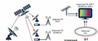
Apparently, the circuit has some kind of elusively successful ratio of ease of control and simplicity of design, which, combined with the unexpected variety of work of the elements, has made it popular for so many years. Because the listed properties, as a result, were expressed in quite even low cost and in applicability in different schemes - both consumer and professional. They are good for use in children's toys, time relays, combination locks, spacecraft. And the annual sales are still in the billions of units around the world. Moreover, for all the time the scheme has not undergone practically any changes. For whatever reason, the word "evolution" under the picture above is taken in quotation marks. The 555 timer is produced by many companies around the world. Domestic analogues of NE555 are also known - the KR1006VI1 microcircuit and its CMOS version KR1441VI1.
Functional diagram and description of the device
The timer functionally consists of 5 components. The circuit has more conclusions than internal blocks, which indicates the possible flexibility of inclusion in various circuit solutions with the participation of this microcircuit.

The input internal voltage divider sets the reference voltages for the two comparators, the high and low. The RS flip-flop receives their signals and generates an output signal, which is sent to the power amplifier. There is also an additional transistor with a collector brought out to the outside, which is used to connect an external timing chain.
The circuit pins are located the same, regardless of the version of the microcircuit


Description of circuit pins
The datasheet below contains the pins and signals applied to them, from which the operation of the microcircuit becomes a little understandable. Although a lot depends on its connection.
| Negative common power output | Positive power output - 8 |
|
| Comparator input # 2 (lower). Low level signal - analog or pulse. | The timer is triggered by a low-level signal (analog or pulse) (threshold - 1/3 Vpit) | Output signal of high level appears on pin 3 |
| Output signal ( high level) depends on the power supply: Vpit - 1.7 V Low level (no signal) - about 0.25 V | The time characteristic of the output signal is determined by an external timing chain consisting of a resistor (or resistors) and capacitance. | |
| Triggered by a low level signal (≤ 0.7 V) | Immediate reset of the output signal | The input signal is independent of the supply voltage |
| Comparator # 1 reference voltage control | The voltage value controls the duration of the output pulses (single-shot) or their frequency (multivibrator). | |
| High level reset signal - analog or pulse | ||
| Time-setting capacitor C discharge circuit | ||
| Positive power wire | Vpit \u003d 4.5 V to 18 V | Minus - 1 |
Application: connection options NE555 (or NE555 analogs)
One vibrator

Capacitor C and resistor R set the duration of the pulse t, issued by the circuit in response to a signal at the Input (pin 2). The supply voltage does not affect the duration, but the amplitude of the output signal. When a pulse is issued, a change in the input signal is not perceived by the circuit. After time t, the circuit outputs the trailing edge of the output signal and returns to the initial stateand is then ready to react to the input signal again. Thus, it can distinguish informative bursts (low level) against the background of noise, since the signal at the input is generally analog. It can work as an anti-bounce circuit.
Pulse generator (multivibrator)
The multivibrator does not need to input any signals, it starts working immediately after turning on the power.

The capacitor C, discharged at the beginning, sets the input to a low level, which causes the timer to work, giving out a high potential at the output. Its duration is determined by charging capacitor C through resistors R1 and R2. Then C is discharged through R2 and input 7, which determines the duration of the pause on the timer. After that, everything is repeated, and at the output, pulses with a given amplitude and durations t 1 and t 2, that is, the frequency f

and duty cycle S \u003d T / t 1. The duty cycle in this simplest connection cannot be more than 2, since the pulse time t 1 is always\u003e the pause time t 2.
Chip integral timer NE555 is a real breakthrough in the field of electronics. It was created in 1972 by Signetics employee Hans R. Camenzind. The invention has not lost its relevance to this day. Later, the device became the basis for timers with doubled (IN556N) and quadruple configuration (IN558N).
Without a doubt, the brainchild of an electronics engineer allowed him to occupy his prominent niche in the history of technical inventions. By sales level this device since its inception, it has surpassed any other. In the second year of its existence, the 555 microcircuit became the most purchased part.
Leadership persisted in all subsequent years. The 555 chip, which increased in use every year, sold very well. For example, in 2003, more than 1 billion copies were sold. The configuration of the unit itself has not changed during this time. It has existed for over 40 years.
The appearance of the device came as a surprise to the creator himself. Camenzind aimed to make the IP flexible in use, but he did not expect it to be so multifunctional. It was originally used as a timer or the 555 Chip, which has expanded rapidly, today it is used from toys for children to spaceships.

The device is robust because it is based on bipolar technology and does not require any special effort to be used in space. Only test work is carried out with particular rigor. So, when testing the NE 555 circuit, individual trial specifications are created for a number of applications. There are no differences in the production of circuits, but the approaches for final inspection differ markedly.
The appearance of the circuit in domestic electronics
The first mention of innovation in the Soviet literature on radio engineering appeared in 1975. An article about the invention was published in the journal "Electronics". The 555 microcircuit, an analogue of which was created by Soviet electronics engineers in the late 80s of the last century, was named KR1006VI1 in domestic radio electronics.
In production, this part was used when assembling the "Electronics VM12" video recorders. But this was not the only analogue, since many manufacturers around the world have created a similar device. All units have a standard DIP8 enclosure, as well as a small SOIC8 enclosure.
Circuit Specifications
Chip 555, which is shown graphically below, includes 20 transistors. The block diagram of the device contains 3 resistors with a resistance of 5 kOhm. Hence the name of the device "555".
The main technical characteristics products are:
- supply voltage 4.5-18V;
- maximum output current 200 mA;
- the power consumption is up to 206 mA.
If we consider it at the exit, then this digital device... It can be in two positions - low (0V) and high (4.5 to 15V). Depending on the power supply unit, the indicator can reach 18 V.
What is the device for?
NE 555 microcircuit is a unified device with a wide range of applications. It is often used in assembly different schemes, and this only makes the product popular. Accordingly, the level of consumer demand rises. Such fame caused a drop in the price of the timer, which pleases many craftsmen.

The internal structure of the 555 timer
What makes this device work? Each of the terminals of the unit is connected to a circuit containing 20 transistors, 2 diodes and 15 resistors.
Doubled model format
It should be noted that the NE 555 (microcircuit) comes in a double format called 556. It contains two free ICs.
The 555 has 8 contacts while the 556 has 14 contacts.
Device operating modes
The 555 chip has three modes of operation:
- Monostable mode of the 555 chip. It works as a one-way one-way. During operation, a pulse of a given length is emitted as a response to the trigger input when the button is pressed. The output is at low voltage until the trigger is turned on. Hence, he got the name waiting (monostable). This principle of operation keeps the device inactive until it is turned on. The mode provides activation of timers, switches, touch switches, frequency dividers, etc.
- Unstable mode is a stand-alone device function. It allows the circuit to remain in generator mode. The output voltage is variable: low or high. This scheme is applicable when it is necessary to give the device jerks of an intermittent nature (when the unit is switched on and off for a short time). The mode is used when the LED lamps are turned on, it functions in logic diagram hours, etc.
- Bistable mode, or Schmidt trigger. It is clear that it works according to the trigger system in the absence of a capacitor and has two stable states, high and low. A low trigger count turns into a high one. When the low voltage is dropped, the system rushes to a low state. This scheme is applicable in the field of railway construction.
Timer pins 555
The 555 chip generator includes eight pins:

- Pin 1 (ground). It is connected to the negative side of the power supply (circuit common).
- Pin 2 (trigger). It supplies high voltage for a while (it all depends on the capacitor). This configuration is monostable. Pin 2 controls pin 6. If the voltage in both is low, then the output will be high. Otherwise, with a high voltage in pin 6 and low in pin 2, the output on the timer will be low.
- Pin 3 (output). Outputs 3 and 7 are in phase. Applying a high voltage of about 2 V and a low voltage from 0.5 V will produce up to 200 mA.
- Pin 4 (reset). The voltage applied to this output is low despite the 555 timer mode. To avoid accidental resets, this output should be connected to the plus side during use.
- Conclusion 5 (control). It opens access to This pin is not used in Russian electronics, but when you connect it, you can achieve broad control capabilities of the 555 device.
- Conclusion 6 (stop). Enters comparator 1. It is opposite to pin 2, it is used to stop the device. This produces a low voltage. This output can take sinusoidal and rectangular pulses.
- Pin 7 (bit). It is connected to the T6 transistor collector, and the emitter of the latter is grounded. When the transistor is open, the capacitor is discharged before it closes.
- Pin 8 (positive side of power supply), which is 4.5 to 18 V.
Applying Output
Output 3 (Output) can have two states:
- Connects the digital output directly to the input of another driver on digital basis... The digital output can control other devices by means of several additional components (power supply voltage is 0 V).
- The voltage reading in the second state is high (Vcc at the power supply).
Unit capabilities
- When the voltage in Output drops, current is sent through the device and connects it. This is the dip, as the current is generated from Vcc and passes through the unit to 0 V.
- With an increase in Output, the current passing through the device ensures its switching on. This process can be called the source of the current. Electricity in this case is produced from a timer and goes through the device to 0 V.
Ascending and descending can function together. Thus, the device is switched on and off alternately. This principle is applicable to the operation of LED lamps, relays, motors, electromagnets. The disadvantages of this property include the fact that the device must be connected to Output different ways, since output 3 can act both as a consumer and as a current source up to 200 mA. The power supply used must be able to supply sufficient current for both devices and the 555 timer.
Chip LM555
Microcircuit 555 Datasheet (LM555) has wide functionality.
It is used from variable duty ratio square wave generators and relays and delayed operation to complex PWM generator configurations. Microcircuit 555 pinout and internal structure are shown in the figure.

The level of accuracy of the fixture is 1% of the calculated indicator, which is optimal. A unit such as the NE 555 datasheet chip is not affected by ambient temperature conditions.
Analogs of the NE555 chip
Microcircuit 555, an analogue of which in Russia was named KR1006VI1, is an integrated device.

Among the working blocks, the RS-trigger (DD1), comparators (DA1 and DA2), at the output, based on a push-pull system and complementary to the VT3 transistor, should be distinguished. The purpose of the latter is to reset the time setting capacitor when using the unit as a generator. The flip-flop is dropped when a logical unit (Jupit / 2 ... Jupit) is applied to the inputs of R.
In the case of resetting the trigger at the output of the device (pin 3), a low voltage indicator will be observed (transistor VT2 is open).
The uniqueness of the 555 scheme
With the functional diagram of the device, it is very difficult to understand what is its singularity. The originality of the device lies in the fact that it has a special trigger control, namely, it generates control signals. Their creation takes place on the comparators DA1 and DA2 (to one of the inputs to which the reference voltage is applied). To generate control signals at the trigger inputs (comparator outputs), signals with high voltage should be obtained.
How to start the device?
To start the timer, output 2 must be energized with a value from 0 to 1/3 Jupit. This signal contributes to triggering the trigger and produces a high voltage signal on output. A signal above the limit will not cause any changes in the circuit, since the reference voltage for the comparator is DA2 and is 1/3 Jupit.
You can stop the timer when you reset the trigger. To this end, the voltage at output 6 must exceed 2/3 Jupit (the reference voltage for the DA1 comparator is 2/3 Jupit). When reset, a low voltage signal and a discharge of the time setting capacitor will be established.
The reference voltage can be adjusted by connecting an additional resistor or power supply to the terminal of the unit.
AT recent times among car owners it has become fashionable to reel in the mileage traveled by the car on the speedometer.
Many are wondering if winding the speedometer on a 555 chip is feasible on your own?

This procedure is not particularly difficult. For its manufacture, a 555 microcircuit is used, which can function as individual components of the circuit can be taken with indicators that deviate by 10-15% from the calculated values.
We continue the review timer 555... In this article, we will consider examples practical application this microcircuit. You can read a theoretical overview.
Example # 1 - Darkness alarm.
Scheme issues sound signal at nightfall. While the photoresistor is illuminated, pin # 4 is set low, which means the NE555 is in reset mode. But as soon as the illumination falls, the resistance of the photoresistor increases and a high level appears at pin No. 4, and as a result, the timer starts, emitting a sound signal.
Example # 2 - Alarm module.

The diagram represents one of the car alarm modules, which gives a signal when the vehicle tilt angle changes. A mercury switch is used as a sensor. In the initial state, the sensor is not closed and the NE555 output is set to a low level. When the angle of inclination of the car changes, the mercury drop closes the contacts, and a low level at pin # 2 starts the timer.
As a result, a high level appears at the output, which controls any executive device. Even after opening the sensor contacts, the timer will still remain active. You can disable it if you stop the timer by applying a low level to pin # 4. C1 - ceramic capacitor with a capacity of 0.1μF ().
Example # 3 - Metronome.

A metronome is a device used by musicians. It counts down the required rhythm, which can be adjusted with a variable resistor. The circuit is built according to the scheme of a rectangular pulse generator. The metronome frequency is determined by the RC chain.
Example # 4 - Timer.

Timer for 10 minutes. The timer is turned on by pressing the "Start" button, while the LED HL1 lights up. After the selected time interval has elapsed, the HL2 LED lights up. The variable resistor can be used to adjust the time interval.
Example # 5 - Schmitt trigger on 555 timer.

This is a very simple yet effective scheme. The circuit allows, by feeding a noisy input analog signal, get a clean square-wave output
555 Timer IC is one of the most used ICs among students and hobbyists. There are many uses for this IC, mainly used as vibrators, ASTABLE MULTIVIBRATOR, MONOSTABLE MULTIVIBRATOR and BISTABLE MULTIVIBRATOR. This article will try to cover the various aspects of the 555 IC timer and explain its operation in detail. So let's first define the concepts of unstable, unstable and bistable vibrators.
ASTABLE MULTIVIBRATOR
This means that there will be no stable output level. So the output will be a fluctuation between high and low. These unstable output parameters are used as a clock for rectangular output for many applications.
SINGLE STABLE MULTIVIBRATOR
This means there will be one steady state and one unstable state. In steady state, high or low can be selected by the user. If the stabilized output is selected high, the Timer will always try to drive the output high. Therefore, with a low level state, the Timer is turned off for a short time and this state is called unstable during this time. If the stable state is selected the minimum value and the interrupt output goes high for a short time until the low value arrives.
[Learn more about Single Stable Multivibrator: 555 Timer Single Stable Multivibrator Circuit]
BISTABLE MULTIVIBRATOR
This means the output state is stable. With each interrupt, the output changes and remains as it is. For example, the output is considered high now with a break, it decreases and remains low. On the next break, he goes high.
[Learn more about Bistable Multivibrator: 555 Timer IC Bistable Multivibrator Circuit]
Important features of the IC 555 Timer
NE555 IC and 8 pin devices. The important electrical characteristics of the Timer are that it should not turn on above 15V, which means that the voltage source cannot be higher than 15V. Secondly, we cannot do more than 100mA from the chip. If you don't follow this, the chip will be burned or damaged.
Explanation of work
The timer basically consists of two main structural elements, and they are:
1.Comparators (two) or two op amps
2.One SR multivibrator (selectable reset trigger)
As shown above, there are only two important components in the Timer, two comparators and a flip-flop. Need to understand what is comparator and trigger.
it is simply a device that compares the voltage across the input terminals (inverting (-VE) and non-inverting (+ VE)). Therefore, depending on the difference in the positive terminal and negative terminal at the input to the port, the output of the comparator is determined.
For example, consider that the positive input terminal will be + 5V and the negative input terminal will be + 3V. The difference is 5-3 \u003d + 2V. Since the difference is positive, we get a positive voltage spike at the comparator output.
Another example: if the positive terminal is + 3V and the negative input terminal is + 5V. Difference + 3- + 5 \u003d -2V, since the input voltage difference is negative. The comparator output will be a negative voltage peak.

If for example, consider the positive input terminal as the input and the negative input terminal as the reference, as shown in the picture above. So the voltage difference between the input and another large positive will get the positive output of the comparator. If the difference is negative, then we get negative or ground at the comparator output.
SR multivibrator: this memory cell can store one bit of data. In the figure we see the truth table.
There are four states of the multivibrator for two inputs; however, we must understand that there are only two trigger states for this case.
| S | R | Q | Q '(Q bar) |
| 0 | 1 | 0 | 1 |
| 1 | 0 | 1 | 0 |
Now, as shown in the table, we get corresponding results for the reset and set inputs. If there is an impulse to set the PIN and a low level at the reset, then the flip-flop retains the value of one and affects the high logic in the Q terminals. This state continues until reset, the PIN receives a pulse during dialing and has low logic. This will reset the flip-flop so the Q output turns off and this state continues until the flip-flop is set again.
Thus, the flip-flop stores one bit of data. Here's another thing, the Q and Q-stroke are always opposite.
In the timer, comparator and flip-flop are combined.
Consider the 9V supplied to the Timer, due to the voltage divider formed by the resistors inside the Timer, as shown in the block diagram; there will be voltage across the comparator contacts. So, because of the mains voltage divider, we will have + 6V at the negative terminal of the first comparator. And + 3V to the positive terminal of the second comparator.
The first and the other contact is one comparator output connected to the reset of the multivibrator contact, so if at the comparator one output goes from low, then the flip-flop will be reset. And on the other hand, the second output of the comparator is connected to the multivibrator, so that if the second output of the comparator goes from a low value, the multivibrator stores one at a time.

At a voltage of at least + 3V across the trigger pin (negative input of the second comparator), the comparator output goes from low to high as discussed earlier. This pulse defines the multivibrator and stores one value.
Now, if we apply a voltage higher than + 6V at the threshold pin (positive input of one comparator), the comparator output goes from low to high. This pulse resets RS and RS stores zero.
Another thing happens during the reset of the flip-flop, when it resets the discharge, it turns out the contact is connected to ground under the name Q1 gets turned on. Transistor T1 turns on because the Q bar is at the high reset mark and is connected to the base of T1.
In an unstable configuration, the connected capacitance drops here at this moment and therefore the output of the timer will be low during this time. In an unstable configuration, the time during the charging of the capacitor to the trigger contact will be less than + 3V and therefore the trigger retains one value and will be high at the output.

In an unstable configuration, as shown in the figure,
The output frequency depends on the RA, RB resistors and capacitor C. The equation is given as,
Frequency (F) \u003d 1 / (time period) \u003d 1.44 / ((RA + RB * 2) * C).
Here RA, RB are the resistance values \u200b\u200band C is the capacitance value. By putting the resistance and capacitance values \u200b\u200binto the above equation, we get the output square wave frequencies.
Time logic high is set as, TH \u003d 0.693 * (RA + RB) * C
Time logic low set as, TL \u003d 0.693 * RB * C
The duty cycle of the output rectangular signal is set as, Duty cycle \u003d (RA + RB) / (RA + 2 * RB).
555 Timer diagram and descriptions

Contact 1. Ground: this pin must be connected to ground.
Pin 8. Power or supply voltage vcc: this pin also has no special function. It is connected to a positive voltage. On the Timer, for the function to work, this pin must be connected to a positive voltage in the range of +3.6 V to + 15 V.
Contact 4. Reset: as discussed earlier, there is a macro switch. The trigger output drives the microcircuit, the output is connected directly to pin 3.
The "reset" pin is directly connected to the MR (master reset) of the flip-flop. When investigating, we can observe a small cycle on the trigger. When SR (master reset) contact is active, the trigger is low. This means that for the flip-flop to reset the SR pin, the voltage must go from high to low. This step down logic in a trigger comes with a hard time going down. Therefore, the output goes poorly, regardless of any conclusions.
This pin is associated with vcc for a trigger to stop with a hard reset.
Pin 3. Output: this pin also has no special function. This contact has a push-pull configuration (PUSH-PULL) formed by transistors.
This configuration is shown in the figure. The bases of the two transistors are connected to the trigger output. So when high logic level appears at the output of the flip-flop, then the NPN transistor turns on and appears at the + V1 output. When the logic appearing at the flip-flop output goes low, the PNP transistor gets ON and the output is connected to ground or –V1 appears at the output.
Thus, how the configuration is used to get the square wave output by the control logic from the flip-flop. The main purpose of this configuration is to get the trigger load back. But the flip-flop cannot release 100mA at the output.
Well, so far we have discussed contacts that do not change the state of the outputs in any state. The remaining four pins are special because they determine the state of the chip's timer output.
Contact 5. Test contact: the control terminal is connected to the negative input terminal of the first comparator.
Consider, for the case, the voltage between vcc and ground is 9V. Due to the voltage divider in the microcircuit, the voltage to the control pin will only be vcc * 2/3 (for the supply voltage vcc \u003d 9, the voltage on the pin \u003d 9 * 2/3 \u003d 6V).
This function gives the user direct control over the first comparator. As shown in the above circuit, the output of the first comparator is fed to the flip-flop reset. We can put different voltages on this pin, say if we connect it to + 8V. Now what is happening is that the contact voltage threshold must reach + 8V before the trigger is reset and be dragged down to the output.
For a normal case, the V-Out will go to a minimum then the capacitor receives a charge of up to 2 / 3VCC (+ 6V for a 9V supply). Now since we have exposed different voltages to the control pin (first comparator negative or reset comparator).
The capacitor must be charged until the control terminal voltage is reached. The strength of the capacitor charge affects the on and off times of the signal change. Therefore, the output signal experiences various interval switches.
Typically this pin is wound down with a capacitor. To avoid unwanted noise and interference in operation.
Pin 2. Trigger:connected to the input of the second comparator. The output of the second comparator is connected to the SET pin of the flip-flop. From the output of the second comparator, we get a high voltage at the output of the timer. So we can say the trigger pin controls the Timer output.
Now here's what you need to observe, the low voltage in the trigger forces the high voltage output, as it is on the inverting input of the second comparator. The voltage on the trigger pin must go below the supply voltage VCC * 1/3 (at VCC 9V, VCC * (1/3) \u003d 9 * (1/3) \u003d 3V). Therefore, the trigger voltage must be below 3V (for a 9V supply) at the timer output to go high.
If this pin is connected to ground, the output will always be high.
Contact 6. Threshold: the voltage threshold contact determines when the trigger is reset in the Timer. The voltage threshold is indicated for the positive input of comparator 1.
Here the voltage difference between the THRESOLD contact and the Control contact determines the comparator 2 output and therefore the logic reset. If the difference voltage is positive, the flip-flop is cleared and the output is reduced. If the difference is negative, then the logic in the SET pin determines the output.
If the entrance control is open. Then a voltage equal to or greater than VCC * (2/3) (i.e. 6V for a 9V supply) will reset the flip-flop. Therefore, the output is low.
Therefore, we can conclude that the voltage threshold contact determines when the output should go low if the control pin is open.
Contact 7. Reset: this pin is taken from the open collector of the transistor. Since the transistor (T1 reset pin) got a Base connection to the Q bar. Whenever the output goes low or the flip-flop gets cleared, the Reset is connected to ground. When the Q bar is high, then Q will be low, so T1 will get an ON change as power has arrived at the base of the transistor.
This pin usually discharges a capacitor in an unstable configuration, hence the name Reset.
Theory Practice Add tagTheory and practice of using the 555 timer. Part two.
Part two. Practical.In this part, we will continue to drive the 555 timer through your brains, but from a practical point of view, we will consider specific circuits for switching on the microcircuit.
So,
Scheme 1:
This thing starts working (beeping) if, for some reason, it suddenly becomes dark. That is, light will no longer enter the LDR1 photoresistor or the luminous flux will decrease to a certain critical level.

This circuit is intended to irritate the auditory nerve if the voltage at the Control input falls below 9 volts.

The simplest form of an alarm node. If S2 is closed, the timer output will be high and will remain high even if the sensor is reset. You can return a low level to the output of the microcircuit with the "Reset" button.

Similar to Scheme 1, though you can adjust the beeping tone frequency with resistor R2.

Metronome. It emits a measured ticking so that novice musicians do not lose their rhythm, or sleep well. The tick frequency is adjusted by resistor R1.

10 minute timer. It is started by pressing the "Reset-start" button, while the HL2 LED lights up, for example - green. After the expiry of the time interval, the HL1 LED will light up, for example - red. The interval can be adjusted with resistor R4.

Schmidt trigger. A useful thing if you need to get rectangular pulses from a sinusoidal signal, even distorted and noisy.

Generator with increased accuracy and stability. The frequency is adjusted by resistor R1. Diodes - any germanium. You can also use Schottky diodes.

Missing impulse detector. It can be useful. The transistor can be replaced with a domestic KT3107.

Two-tone siren. An interesting scheme for experimenting with the inclusion of two timers at once.
Well, for now.
We add up the questions, as usual