A capacitor is an element of an electrical circuit that serves as a charge storage.
There are many areas of application of this device now, which is the reason for their large assortment. They differ in materials from which they are made, purpose, range of the main parameter. But the main characteristic of a capacitor is its capacity.
The principle of the condenser
Design
In the diagrams, the capacitor is indicated as two parallel lines that are not connected to each other:
This corresponds to its simplest design - two plates (plates) separated by a dielectric. The actual performance of this product is most often wrapped in a roll of covers with a layer of dielectric or other bizarre shapes, but the essence remains the same.
Electrical capacity - the ability of a conductor to accumulate electrical charges. The more the charge holds the conductor at a given potential difference, the greater the capacity. The relationship between the charge Q and the potential φ is expressed by the formula:
where Q is the charge in coulombs (C), φ is the potential in volts (V).
 Capacity is measured in farads (F), which you remember from physics lessons. In practice, smaller units are more common: millifarad (mF), microfarad (μF), nanofarad (nF), picofarad (pF).
The storage capacity depends on the geometric parameters of the conductor, the dielectric constant of the medium where it is located. So, for a sphere made of a conducting material, it will be expressed by the formula:
C \u003d 4πεε0R
where ε0-8.854 · 10 ^ -12 F / m, the electrical constant, and ε is the dielectric constant of the medium (tabular value for each substance).
In real life, we often have to deal not with one conductor, but with systems of such. So, in an ordinary flat capacitor, the capacitance will be directly proportional to the area of \u200b\u200bthe plates and inversely to the distance between them:
C \u003d εε0S / d
ε here is the dielectric constant of the spacer between the plates.
Capacity of parallel and serial systems
The parallel connection of the capacitors is one large capacitor with the same dielectric layer and the total area of \u200b\u200bthe plates, therefore the total capacity of the system is the sum of those for each of the elements. The voltage when connected in parallel will be the same, and the charge will be distributed between the circuit elements.
C \u003d C1 + C2 + C3
The series connection of capacitors is characterized by the total charge and the distributed voltage between the elements. Therefore, it is not the capacity that is summed up, but its reciprocal:
1 / C \u003d 1 / C1 + 1 / C2 + 1 / C3
From the formula for the capacity of a single capacitor, it can be deduced that with the same elements connected in series, they can be represented as one large one with the same plate area, but with the total dielectric thickness.
Reactance
The capacitor cannot conduct direct current, which is evident from its design. In such a circuit, it can only be charged. But in AC circuits, it works great, constantly recharging. If not the restrictions emanating from the properties of the dielectric (it can be broken through when the voltage limit is exceeded), this element would be charged infinitely (the so-called ideal capacitor, something like an absolutely black body and ideal gas) in a DC circuit, and the current through it will not pass. Simply put, the resistance of a capacitor in a DC link is infinite.
With alternating current, the situation is different: the higher the frequency in the circuit, the lower the resistance of the element. Such resistance is called reactance, and it is inversely proportional to frequency and capacitance:
Z \u003d 1 / 2πfC
where f is the frequency in hertz.
Energy storage
The energy stored by a charged capacitor can be expressed by the formula:
E \u003d (CU ^ 2) / 2 \u003d (q ^ 2) / 2C
where U is the voltage between the plates, and q is the accumulated charge.
Oscillating capacitor
In a closed loop containing a coil and a capacitor, an alternating current can be generated.
After charging the capacitor, it will begin to self-discharge, giving an increasing current in strength. The energy of the discharged capacitor will become zero, but the magnetic energy of the coil will be maximum. A change in the magnitude of the current causes the EMF of the self-induction of the coil, and by inertia it will pass the current towards the second plate until it is fully charged. In the ideal case, such oscillations are endless, but in reality they quickly fade away. The oscillation frequency depends on the parameters of both the coil and the capacitor:

where L is the inductance of the coil.
A capacitor can have its own inductance, which can be observed when the frequency of the current in the circuit increases. Ideally, this value is insignificant, and it can be neglected, but in reality, when the plates are rolled plates, this parameter cannot be ignored, especially when it comes to high frequencies. In such cases, the capacitor combines two functions, and is a kind of oscillatory circuit with its own resonant frequency.
Performance characteristics
In addition to the above capacitance, self-inductance and energy capacity, real capacitors (and not ideal ones) have a number of properties that must be taken into account when choosing this element for a circuit. These include:

To understand where the losses come from, it is necessary to clarify what the graphs of sinusoidal current and voltage in this element are. When the capacitor is charged to the maximum, the current in its plates is zero. Accordingly, when the current is at its maximum, there is no voltage. That is, voltage and current are 90 degrees out of phase. Ideally, a capacitor only has reactive power:
Q \u003d UIsin 90
In reality, the capacitor plates have their own resistance, and part of the energy is spent on heating the dielectric, which causes its losses. Most often they are insignificant, but sometimes they cannot be neglected. The main characteristic of this phenomenon is the dielectric loss tangent, which is the ratio of active power (given by small losses in the dielectric) and reactive power. This value can be measured theoretically by presenting the real capacitance in the form of an equivalent equivalent circuit - parallel or serial.
Determination of the tangent of the angle of dielectric loss
When connected in parallel, the loss is determined by the ratio of the currents:
tgδ \u003d Ir / Ic \u003d 1 / (ωCR)
In the case of a series connection, the angle is calculated by the stress ratio:
tgδ \u003d Ur / Uc \u003d ωCR
In reality, for measuring tgδ, a device assembled on a bridge circuit is used. It is used to diagnose insulation losses in high-voltage equipment. Other network parameters can be measured using measuring bridges.
Rated voltage
This parameter is indicated on the label. It shows the limit value of the voltage that can be applied to the plates. Exceeding the rating can lead to breakdown of the capacitor and its failure. This parameter depends on the properties of the dielectric and its thickness.
Polarity
Some capacitors have polarity, that is, it must be connected to the circuit in a strictly defined way. This is due to the fact that an electrolyte is used as one of the plates, and an oxide film on the other electrode serves as a dielectric. When the polarity changes, the electrolyte simply destroys the film and the capacitor stops working.
Tank temperature coefficient
It is expressed by the ratio ΔC / CΔT where ΔT is the change in ambient temperature. Most often, this dependence is linear and insignificant, but for capacitors operating in aggressive conditions, TKE is indicated in the form of a graph.
 The failure of the capacitor is due to two main reasons - breakdown and overheating. And if, in the event of a breakdown, some of their types are capable of self-healing, then overheating over time leads to destruction.
Overheating is caused by both external factors (heating of neighboring circuit elements) and internal ones, in particular, the successive equivalent resistance of the plates. In electrolytic capacitors, it leads to the evaporation of the electrolyte, and in semiconductor oxide capacitors - to breakdown and a chemical reaction between tantalum and manganese oxide.
The danger of destruction is that it often happens with a probability explosionhousing.
Technical design of capacitors
Capacitors can be classified into several groups. So, depending on the ability to adjust the capacity, they are divided into constant, variable and trimming. They can be cylindrical, spherical and flat in shape. You can divide them by purpose. But the most common classification is the type of dielectric.
Paper capacitors
The dielectric used is paper, very often oiled. As a rule, such capacitors are distinguished by their large size, but there were also options in a small design, without oiling. They are used as stabilizing and storage devices, and are gradually being replaced from consumer electronics by more modern film models.
In the absence of oiling, they have a significant drawback - they react to air humidity even with sealed packaging. Damp paper increases energy loss.
Dielectric in the form of organic films
Films can be made from organic polymers such as:
- polyethylene terephthalate;
- polyamide;
- polycarbonate;
- polysulfone;
- polypropylene;
- polystyrene;
- fluoroplastic (polytetrafluoroethylene).
Compared to the previous ones, such capacitors are more compact in size, do not increase dielectric losses with increasing humidity, but many of them are at risk of failure due to overheating, and those that do not have this drawback are more expensive.
Solid inorganic dielectric
This can be mica, glass and ceramics.
The advantage of these capacitors is considered to be their stability and linearity of the dependence of the capacitance on temperature, applied voltage, and for some, even on radiation. But sometimes this dependence itself becomes a problem, and the less pronounced it is, the more expensive the product.
Oxide dielectric
Aluminum, solid-state and tantalum capacitors are available with it. They have polarity, so they fail if they are incorrectly connected and if the voltage rating is exceeded. But at the same time they have good capacity, are compact and stable in operation. With proper operation, they can work for about 50 thousand hours.
Vacuum
Such devices represent a glass or ceramic flask with two electrodes, from which air is pumped out. There are practically no losses in them, but their low capacity and fragility limit the scope of their application to radio stations, where the capacity value is not so important, but the resistance to heating is of fundamental importance.
Electrical double layer
If you look at what a capacitor is for, then you can understand that this type is not really it. Rather, it is an additional or backup power source, which is what they are used for. Some category of such devices - ionistors - contain activated carbon and an electrolyte layer, others work on lithium ions. The capacity of these devices can be up to hundreds of farads. Their disadvantages include high cost and resistance with leakage currents.
 Whatever the capacitor, there are two mandatory parameters that must be reflected in the marking - its capacity and nominal voltage.
In addition, most of them have an alphanumeric designation of its characteristics. In accordance with Russian standards, capacitors are marked with four characters.
The first letter K means "capacitor", the next number is the type of dielectric, followed by an indication of the destination in the form of a letter; the last icon can mean both the design type and the development number, this already depends on the manufacturer. The third point is often overlooked. Such marking is used on sufficiently large products where it can be placed. According to GOST, the decryption will look like this:
First letters:
- K is a constant capacitor.
- CT - trimmer.
- KP - variable capacitor.
The second group is the type of dielectric:

All this cannot be placed on small capacitors, so abbreviated markings are used there, which, out of habit, may even require a calculator, and sometimes a magnifying glass. This marking encodes capacity, voltage rating and deviations from the main parameter. It makes no sense to apply the rest of the parameters: these are, as a rule, ceramic capacitors.
Ceramic capacitor marking
 Sometimes everything is simple with them - the capacity is marked with a number and units: pF - picofarad, nF - nanofarad, μF - microfarad, mF - millifarad. That is, 100nF can be read directly. The denomination, respectively, is a number and a letter V. But sometimes this does not fit, therefore abbreviations are used. So, often the capacity fits in three digits (103, 109, etc.), where the latter means the number of zeros, and the first two - the capacity in picofarads. If there is a number 9 at the end, then there are no zeros, and a comma is placed between the first two. With the number 8 at the end, the comma is moved one more character back.
For example, the designation 109 stands for 1 picofarad, and 100–10 picofarad; 681-680 picofarads, or 0.68 nanofarads, and 104-100 thousand pF or 100nF
You can often find the first letter of the unit as a comma: p50–0.5 pF, 1n5–1.5 nF, 15μ - 15 μF, 15m - 15 mF. Sometimes R is written instead of p.
After three digits, there may be a letter indicating the range of the capacity parameter:

If you calculate the characteristic of the circuit in SI units, then in order to find the capacitance in farads, you must remember the exponents of the number 10:
- -3 - millifarads;
- -6 - microfarads;
- -9 - nanofarads;
- -12 - picofarads.
Thus, 01 pF is 0.1 * 10 ^ -12 F.
On SMD devices, the capacitance in picofarads is indicated by a letter, and the number after it is a power of 10, by which this value must be multiplied.
| letter | C | letter | C | letter | C | letter | C |
| A | 1 | J | 2,2 | S | 4,7 | a | 2,5 |
| B | 1,1 | K | 2,4 | T | 5,1 | b | 3,5 |
| C | 1,2 | L | 2,7 | U | 5,6 | d | 4 |
| D | 1,3 | M | 3 | V | 6,2 | e | 4,5 |
| E | 1,5 | N | 3,3 | W | 6,8 | f | 5 |
| F | 1,6 | P | 3,6 | X | 7,5 | m | 6 |
| G | 1,8 | Q | 3,9 | Y | 8,2 | n | 7 |
| Y | 2 | R | 4,3 | Z | 9,1 | t | 8 |
The rated operating voltage in the same way can be marked with a letter if it is problematic to write it completely. In Russia, the following standard for the letter designation of the denomination has been adopted:
| letter | V | letter | V |
| I | 1 | K | 63 |
| R | 1,6 | L | 80 |
| M | 2,5 | N | 100 |
| A | 3,2 | P | 125 |
| C | 4 | Q | 160 |
| B | 6,3 | Z | 200 |
| D | 10 | W | 250 |
| E | 16 | X | 315 |
| F | 20 | T | 350 |
| G | 25 | Y | 400 |
| H | 32 | U | 450 |
| S | 40 | V | 500 |
| J | 50 |
Despite the lists and tables, it is still better to study the encoding of a particular manufacturer - they may differ in different countries.
Some capacitors are supplied with a more detailed description of their characteristics.


Capacitor properties
The capacitor does not pass direct current and is an insulator for it.
For alternating current, the capacitor is not an obstacle. The resistance of a capacitor (capacitive resistance) to an alternating current decreases with an increase in its capacity and frequency of the current, and vice versa, increases with a decrease in its capacity and frequency of current.
The property of a capacitor to provide different resistance to alternating current has found widespread use. Capacitors are used for filtering, separating some frequencies from others, separating the variable component from the constant ...
What are capacitors made of
The simplest capacitor consists of 2 metal plates (plates), separated by an insulator (dielectric). If one capacitor plate is charged positively and the other negatively, then opposite charges, attracting to each other, will be held on the plates. Therefore, the capacitor can be a storage device for electrical energy.
Capacitor plates are usually made of aluminum, copper, silver, tantalum. Special capacitor paper, mica, synthetic films, air, special ceramics, etc. are used as a dielectric.
If you use foil plates and a multilayer film dielectric, you can make roll-type capacitors, in which the specific storage capacity is approximately in the range from 0.1 J / kg to 1 J / kg or from 0.03 mWh / kg to 0.3 mWh / kg. Due to their low specific storage capacity, capacitors of this type are not suitable for long-term storage of a significant amount of energy, but they are widely used as sources of reactive power in AC circuits and as capacitive resistances. Energy can be accumulated much more efficiently in electrolytic capacitors, the principle of which is shown in Fig. 2.
1 metal sheet or foil (aluminum, tantalum, etc.),
2 dielectric made of metal oxide (Al2O3, Ta2O5 or others),
3 paper, etc., impregnated with electrolyte (H3BO3, H2SO4, MnO2, etc.) and glycerin. Since the thickness of the dielectric layer in this case usually remains within 0.1 µm, these capacitors can be made with a very large capacity ( up to 1 F), but at a relatively low voltage (usually a few volts).
Ultracapacitors (supercapacitors, supercapacitors) can have even greater capacitance, the plates of which are a double electric layer several tenths of a nanometer thick at the interface between an electrode made of microporous graphite and an electrolyte (Fig. 3).
1 electrodes made of microporous graphite,
2 electrolyte
The effective area of \u200b\u200bthe plates of such capacitors reaches, due to the porosity, up to 10,000 m2 for each gram of the electrode mass, which makes it possible to achieve a very large capacity with very small capacitor dimensions. Ultracapacitors are currently available for voltages up to 2.7 V and capacities up to 3 kF. Their specific storage capacity is usually in the range from 0.5 Wh / kg to 50 Wh / kg and there are prototypes with a specific storage capacity up to 300 Wh / kg.
They are beneficial when energy is consumed in the form of short pulses (for example, to power the starter of internal combustion engines) or when a quick (one-second) charging of the storage device is required. For example, in 2005, a trial operation of ultracapacitor buses began in Shanghai, the capacitor bank of which is charged while the bus is parked at each stop.
When choosing a capacitor for a specific device, the following circumstances should be considered:
a) the required value of the capacitance of the capacitor (μF, nF, pF),
b) the operating voltage of the capacitor (the maximum voltage value at which the capacitor can work for a long time without changing its parameters),
c) the required accuracy (possible scatter of capacitor capacitance values),
d) temperature coefficient of capacitance (the dependence of the capacitance of the capacitor on the ambient temperature),
e) capacitor stability,
f) leakage current of the capacitor dielectric at rated voltage and given temperature. (The dielectric resistance of the capacitor may be indicated.)
Application
All radio and electronic devices, except for transistors and microcircuits, use capacitors. In some circuits there are more of them, in others there are fewer, but almost no electronic circuit can exist without capacitors at all.
At the same time, capacitors can perform a variety of tasks in devices. First of all, these are capacities in filters of rectifiers and stabilizers. With the help of capacitors, a signal is transmitted between the amplifying stages, low and high frequency filters are built, time intervals in time delays are set, and the frequency of oscillations in various generators is selected.
Capacitors trace their ancestry to the Leyden jar, which was used in his experiments by the Dutch scientist Peter van Muschenbruck in the middle of the 18th century. He lived in the city of Leiden, so it's not hard to guess why this bank was called that.
Actually, it was an ordinary glass jar, lined inside and outside with tin foil - staniol. It was used for the same purposes as modern aluminum, but then aluminum was not yet discovered. The only source of electricity in those days was an electrophore machine, capable of developing voltages up to several hundred kilovolts. It was from her that they charged the Leyden jar. Physics textbooks describe the case when Mushenbrook discharged his can through a chain of ten guardsmen holding hands, while no one knew the consequences could be tragic. The blow was quite sensitive, but not fatal. It did not come to this, because the capacity of the Leyden jar was insignificant, the pulse turned out to be very short-lived, so the discharge power was not high.
Capacitors are not just radio and electrical circuitry. In nature, we meet with natural capacitors during a thunderstorm, when oppositely charged clouds are discharged relative to each other or to the ground. Lightning is formed and thunder rumbles.
Capacitors are widely used in power supply systems of industrial enterprises and electrified railways to improve the use of electrical energy in alternating current. On e. p. from. and diesel locomotives, capacitors are used to smooth the pulsating current received from rectifiers and pulse interrupters, to combat arcing of contacts of electrical devices and radio interference, in control systems for semiconductor converters, and also to create a symmetrical three-phase voltage required to power the electric motors of auxiliary machines. In radio engineering, capacitors are used to create high-frequency electromagnetic oscillations, to separate DC and AC electric circuits, etc. 1. In radio engineering and television equipment - to create oscillatory circuits, their tuning, blocking, separation of circuits with different frequencies, in rectifier filters, etc. etc.
2.In radar technology - for receiving pulses of higher power, pulse shaping, etc.
3. In telephony and telegraphy - for separating alternating and direct current circuits, separating currents of different frequencies, spark extinguishing in contacts, balancing cable lines, etc.
4. In automation and telemechanics - for creating sensors on the capacitive principle, separating circuits of constant and pulsating currents, spark extinguishing in contacts, in circuits of thyratronic pulse generators, etc.
5. In the technology of computing devices - in special storage devices, etc.
6. In electrical engineering - for creating samples of capacitance, obtaining variable capacitance (capacitance stores and laboratory variable capacitors), creating measuring instruments based on the capacitive principle, etc.
7. In laser technology - to obtain powerful pulses.
In modern electric power industry, capacitors also find themselves very diverse and responsible applications:
to improve power factor and industrial installations (cosine or shunt capacitors);
for longitudinal compensation capacity of long-distance transmission lines and for voltage regulation in distribution networks (serial capacitors);
for capacitive energy extraction from high voltage transmission lines and for connecting special communication equipment and protective equipment (coupling capacitors) to transmission lines;
for overvoltage protection;
for use in voltage pulse circuits (GVP) and generators of powerful current pulses (PCG) used in testing electrical equipment;
for electric discharge welding;
for starting capacitor electric motors (starting capacitors) and for creating the required phase shift in the additional winding of these motors;
in lighting devices with fluorescent lamps;
to suppress radio interference created by electric machines and the rolling stock of electrified vehicles.
In addition to electronics and power engineering, capacitors are also used in other non-electrical areas of technology and industry for the following main purposes:
In the metal industry - in high-frequency installations for melting and heat treatment of metals, in electroerosive (electrospark) installations, for magnetic pulse processing of metals, etc.
In the mining industry (coal, metal ore, etc.) - in mine transport on capacitor electric locomotives of normal and high frequency (contactless), in electric explosive devices using the electrohydraulic effect, etc.
In automotive engineering - in ignition circuits for spark extinguishing in contacts and for suppressing radio interference.
In medical technology - in X-ray equipment, in electrotherapy devices, etc.
In the technology of using atomic energy for peaceful purposes - for the manufacture of dosimeters, for the short-term production of large currents, etc.
In photographic technology - for aerial photography, obtaining a flash of light in ordinary photography, etc.
The variety of applications leads to an exceptionally wide variety of capacitor types used in modern technology. Therefore, along with miniature capacitors weighing less than a gram and dimensions of the order of several millimeters, one can find capacitors weighing several tons and exceeding human height in height. The capacity of modern capacitors can range from fractions of a picofarad to several tens and even hundreds of thousands of microfarads per unit, and the nominal operating voltage can range from several volts to several hundred kilovolts.
The role of a capacitor in an electronic circuit is to accumulate electrical charge, separate the DC and AC components of the current, filter the pulsating current, and much more.
In Soviet times, when many stationary electronic clocks were powered from an outlet, and compact and cheap batteries had not yet been invented, craftsmen put capacitors there so that in the event of a power outage, for example, for a short time, they could work and not interrupt their speed.
§ 1.1. Functions and Applications
Electrical capacitors into electrons
ny, radio engineering, electrical
and electric power devices performed
function of energy storage, source
nickname of reactive power, frequency-dependent
simulated reactance. Implement
they do it thanks to their ability
ability to accumulate electrical energy,
and then give it to the load circuit.
High power current pulses are used
used to create extreme
by the intensity of magnetic fields and power
arc discharges in gases and liquid
Pulses high and ultra high
stresses are used in high-
their voltages in test and research
for promotional purposes.
Capacitive energy storage devices used
are used in research facilities
plasma physics, thermonuclear reactions,
testing of various equipment, in electrical
rotechnological devices (magnetic
impulse stamping, installations, use
causing electrohydraulic shock, im-
pulse electric welding, magnetization,
ultrasonic technology, electro-spark
processing technology, electroplasma
lease, etc.). Storage capacitors
widely used in various devices
state of impulse communication, radar,
navigation, in pulsed light sources
ta (high-intensity sources - lam-
dust flashes, signal installations - may-
ki, optical quantum generators - la-
zera, etc.), pulsed X-ray
Capacitors are used in technology
seismic survey (electrodynamic im-
pulse excitation of elastic waves in the earth
bark), to detonate detonators, in the
dicine (pulse defibrillator)
Drives for generators of powerful
current pulses can be the simplest (in
the form of a condenser or condenser banks
tori) and more complex (artificial
long lines, such as chain shape
maker, or a set of parallel LC-
shapers).
They have capacitors relatively long
go accumulate electrical energy from
a relatively low-power source, and
then they quickly give it to the load. At the same time
power capacitors are used in
in particular, in bottom-capacitor intelligent
residents of tension.
The main workflow in a number
devices with capacitive energy storage
gii is not giving it to the load, but
accumulation. Capacitor capacity
quickly accumulate electrical energy
giyu is used to create various
devices for the protection of electrical equipment
ore and its elements from overvoltage
due to thunderstorm or com-
mutational phenomena. This property, and
also relatively small dimensions, high
high reliability of capacitors due to
were, in particular, their widespread use
damping circuits of powerful
high-voltage converters for high
equalization of voltages on successive
but included valves.
In thyristor converters (you-
rectifiers, inverters, pulse regulators
lators), in contactless switching
in equipment, capacitors are used
for forced switching on and off
diodes and valves with incomplete control
flexibility. Switching capacitors
in contactless devices work in
cumulative mode, while in pre-
educators workflows usually
but charge and discharge (or re-
charge) of the capacitor.
Capacitor property to accumulate
electrical energy is widely used -
xia and to suppress impulse noise in
various electronic equipment for
creating computer memory cells, integrating
niya and differentiation of electrical
signals (analog computers, automatic
tomatoes, controls, etc.).
Accumulative
properties of capacitors when used
in a variety of impulse devices
low power: in pulse generators
current and voltage of special shape
(deploying, measuring devices
wa n etc.). in self-oscillating and descent
out devices. Capacitors very often serve as a source of reactive power
nosti. This property manifests itself then,
when they are affected by the variable
(usually sinusoidal in shape) voltage
living. The current flowing through the condenser
torus, ahead of the voltage by an angle close to
cue to π / 2, i.e., a capacitor, almost does not
consuming active power, it generates
reactive. This ability is used
to improve the power factor
consumers of electrical energy by
partial or full compensation for them
reactive power, which reduces losses
energy in generators, transformers,
electrical networks, increases the stability
parallel operation of power systems,
stabilizes consumer voltage.
To increase the stability of the parallel
work and throughput
power lines, as well as to improve
changes in the operating mode of power systems
change the settings of the longitudinal compensation
tion, the main element of which is
all powerful capacitor banks,
compensating inductive
resistances of high-voltage lines
power transmission. Longitudinal installations
reactive power compensation used
run on electrified railways
Recently, condensate batteries
ditch of longitudinal compensation of steel examples
for ore thermal smelters
high-power furnaces (thousands and ten
ki thousand kilowatts), i.e., with a sharp over-
changing load.
Longitudinal capacitive compensation
reactive power is effectively used
used for starting asynchronous machines
high power when they are powered by
niyam with high resistance (lines
insufficient power and relatively
long length). In power systems,
sensors are used in batteries as
longitudinal and transverse centralized
bathroom reactive power compensation.
They provide a reduction in energy losses
gii and improve the operating modes of energy
systems (together with power plants
provide the necessary stresses in
nodes and energy flows). In both forms
batteries used in series
parallel connection of a large number
single capacitors.
Capacitors are not widely used
only in centralized installations
reactive power compensation, but also in
installations for group and individual
noah compensation. Such examples can
can serve as capacitors for lighting
covs with gas discharge lamps, starting
and working capacitors of single-phase asynchronous
chronic electric motors (in this case
the main function of capacitors is
is involved in creating a phase shift of π / 2
between the currents of the motor windings),
sensors increasing very low
induction power factor
electrothermal industrial plants
noise and high frequencies. Group and
individual reactive compensation
power of consumers gives a great eco-comic effect due to a decrease in
energy losses during its transmission, reduce
voltage drop at peak
reconstruction of energy networks (due to
insufficient power supply lines,
transformers, etc.).
The ability of capacitors to compensate
adjust the reactive power of consumers
electricity is applied not only to
frequency 50-6 0 Hz, but also at increased
operating frequencies, for example, onboard systems
those vehicles, electrothermal
installations. In this case, the essential
but the weight and dimensions of the primary
th generator of electricity.
Reagent capacitor compensation
noise power of the asynchronous machine allows
it creates asynchronous generators,
effective at variable speed
primary engine (hydraulic
sky, gas turbines). They contain condensate
ry provide excitation of the magnetic
flow and reactive power compensation
load.
Full compensation by capacitors
reactive power of inductive coils
also occurs in powerful
test circuits of radio transmitters
transmitters. Impossible without capacitors
operation of these devices with a high
useful action and small
sensations, as well as generating pain
their active capacities.
Another property of capacitors is to measure
understand its reactance at
alternating current is inversely proportional
frequency (x c \u003d 1/2 π / C) -broad about the use
used when creating various filters in
radio engineering, electronic, electrical
technical devices used for
separation of voltages and currents of various
Low, high pass filters,
owls and rejection, representing co-
fight a combination of inductive and capacitive,
resistive and capacitive elements, which are
are integral nodes of most
electronic and radio engineering devices.
Filters are also used in energy
iCal systems. With their help, low-power
high frequency signals applied
for communication, telemechanics, communication systems
emergency automation and other purposes,
are separated from industrial stresses
high voltage frequency. Power
filters are used in the power supply
ke to approximate the voltage waveform to
sinusoidal in the presence of sources
higher harmonics (rectifiers), arc-
furnaces, etc.), in power semiconductors
nickname converters operating in
stand-alone or network-slave.
In reactive filters, resonant
voltage multipliers and other devices
properties use resonant properties
circuits consisting of capacitors to and
ducts.
Capacitors are used in filters
not only variable, but constant
current, in which the useful component
is constant voltage, and the task
filter is to smooth out bullets
stress (by reducing over-
variable component), i.e. here one-
temporarily used the ability to con-
the denser to accumulate energy and reduce
its resistance with frequency. Such
filters are used in power supplies
various electronic and electrical
electronic devices, for example, in high-voltage
installations of electrostatic painting
ki, gas cleaning, in pulse stabilization
voltage tori, EV M, etc.
The property of capacitors to reduce their
resistance with increasing frequency caused
their widespread use in electronic
radio and electronic equipment in
as a blocking or noise suppression
element. The role of the capacitor in
this and in the previous cases concludes
xia is to close the path of high-
total currents, preventing their passage
through other circuits and elements of the device
swarms, for example, into the mains.
Capacitors are integral
element of phase-shifting circuits of electric
electronic devices of automation systems, control
control, in LC- and RC-generators, in ac-
active filters, etc.
One of the many tasks solved
using capacitors, concludes
xia in the division of alternating voltage,
carried out with various changes
y in high-voltage circuits, in electric power
hetic systems, test installations
new, in an even distribution of
tension at discontinuous air
stuffy high-voltage switches and
for other purposes.
Capacitors are widely used:
In capacitive voltage dividers
for the extraction of energy from high-voltage lines
power transmission (at low power
the cost of condenser extraction
lower cost of the power take-off device
using conventional transformers);
As ballast resistance in any
minescent light sources, lamps
incandescent, as well as in low-power devices
triad for battery charging;
In secondary power supplies with
special characteristics (stabilization
current and voltage congestion), in particular, in
inductive-capacitive converters,
serving for constant current supply
plasma technology installations, welding
Inductive-capacitive devices for
change and for balancing the voltage
three-phase network in the presence of unsym-
metric consumers, as well as for creating
giving splitters of the number of phases, it is necessary
for power supply of three-phase consumers
from a single-phase network.
Thus, the scope
capacitors are wide enough: energy
tick, industry, transport, device
communications, automation, broadcasting, location,
measuring and computing technology
Directory
on electrical
capacitors
General information,
selection and application
General editorship
candidate of technical sciences
V.V. Ermuratsky about
Much has been written about capacitors, is it worth adding a couple thousand more words to the millions that already exist? I'll add it! I believe that my presentation will be useful. After all, it will be done taking into account.
What is an electric capacitor
In Russian, the capacitor can be called "storage". It's even clearer that way. Moreover, this is how this name is translated into our language. A glass can also be called a capacitor. Only he accumulates liquid in himself. Or a bag. Yes, a bag. It turns out to be a drive too. It accumulates in itself everything that we put there. What does the electric condenser have to do with it? It is the same as a glass or a bag, but only accumulates an electric charge.
Imagine a picture: an electric current passes through the circuit, resistors, conductors meet in its path and, bam, a capacitor (glass) appeared. What will happen? As you know, current is a flow of electrons, and each electron has an electric charge. Thus, when someone says that a current is passing through the circuit, you imagine millions of electrons running along the circuit. It is these same electronics, when a capacitor appears in their path, and accumulate. The more we push electrons into the capacitor, the more its charge will be.
The question arises, how many electrons can be stored in this way, how many will fit into the capacitor and when will it "eat"? Let's find out. Very often, a comparison with water and pipes is used to simplify the explanation of simple electrical processes. Let's use this approach too.

Imagine a pipe through which water flows. At one end of the pipe, there is a pump that forces water into that pipe. Then, mentally place a rubber membrane across the pipe. What will happen? The membrane will begin to stretch and strain under the action of the water pressure in the pipe (the pressure is created by the pump). It will stretch, stretch, stretch and, as a result, the elastic force of the membrane will either balance the force of the pump and the flow of water will stop, or the membrane will break (If this is not clear, imagine a balloon that will burst if you pump it too hard)! The same thing happens in electrical capacitors. Only there, instead of a membrane, an electric field is used, which grows as the capacitor charges and gradually balances the voltage of the power source.
Thus, the capacitor has a certain limiting charge, which it can accumulate and after exceeding which it will occur dielectric breakdown in a capacitor it will break and stop being a capacitor. It's time, apparently, to tell how the capacitor works.
How an electric capacitor works
At school, you were told that a capacitor is such a thing, which consists of two plates and a void between them. These plates were called capacitor plates and wiring was connected to them in order to supply voltage to the capacitor. So modern capacitors are not very different. They all also have plates and there is a dielectric between the plates. Due to the presence of a dielectric, the characteristics of the capacitor are improved. For example, its capacity.
In modern capacitors, different types of dielectrics are used (more on that below), which are pushed between the capacitor plates in the most sophisticated ways to achieve certain characteristics.
Principle of operation
The general principle of operation is quite simple: voltage is applied - the charge has accumulated. The physical processes that are taking place at the same time should not interest you very much, but if you want, you can read about it in any book on physics in the section of electrostatics.
DC capacitor
If we put our capacitor in an electrical circuit (Fig. Below), turn on an ammeter in series with it and supply a direct current to the circuit, then the ammeter needle twitches for a short time, and then freezes and will show 0A - no current in the circuit. What happened?

We will assume that before the current was supplied to the circuit, the capacitor was empty (discharged), and when the current was applied, it began to charge very quickly, and when it was charged (the electric field between the capacitor plates balanced the power source), the current stopped (here is the graph of the capacitor charge).
That is why it is said that a capacitor does not pass direct current. In fact, it passes, but a very short time, which can be calculated by the formula t \u003d 3 * R * C (The charging time of the capacitor to a volume of 95% of the nominal. R is the resistance of the circuit, C is the capacitance of the capacitor) This is how the capacitor behaves in a constant circuit current. It behaves in a completely different way in a variable chain!
AC capacitor
What is alternating current? This is when electrons "run" first there, then back. Those. the direction of their movement changes all the time. Then, if an alternating current runs along the circuit with a capacitor, then "+" charge, then "-" will accumulate on each of its plates. Those. an alternating current will actually flow. This means that the alternating current passes through the capacitor "unimpeded".
This entire process can be modeled using the hydraulic analogy method. The picture below is an analogue of an AC circuit. The piston pushes the fluid forward and backward. This causes the impeller to spin back and forth. It turns out, as it were, an alternating fluid flow (read alternating current).

Let's now place a model of a capacitor in the form of a membrane between the source of force (piston) and the impeller and analyze what will change.

It looks like nothing will change. As the liquid made oscillatory movements, so it does them, as the impeller oscillated because of this, it will oscillate. This means that our membrane is not an obstacle to variable flow. It will also be for an electronic capacitor.
The fact is that even though the electrons that run along the chains and do not cross the dielectric (membrane) between the capacitor plates, outside the capacitor, their motion is oscillatory (back and forth), i.e. alternating current flows. Eh!
Thus, the capacitor passes the alternating current and delays the direct current. This is very convenient when you need to remove the DC component in the signal, for example, at the output / input of an audio amplifier, or when you want to view only the variable part of the signal (ripple at the output of a DC voltage source).

Capacitor reactance
The capacitor has resistance! In principle, this could be assumed already from the fact that no direct current passes through it, as if it were a resistor with sooooo high resistance.
Alternating current is another matter - it passes, but experiences resistance from the capacitor side:

f - frequency, С - capacitance of the capacitor. If you look closely at the formula, you will see that if the current is constant, then f \u003d 0 and then (may the militant mathematicians forgive me!) X c \u003d infinity.And there is no direct current through the capacitor.
But the resistance to alternating current will change depending on its frequency and the capacitance of the capacitor. The higher the frequency of the current and the capacitance of the capacitor, the less it resists this current and vice versa. The faster the voltage changes
voltage, the greater the current through the capacitor, this explains the decrease in Xc with increasing frequency.

By the way, another feature of the capacitor is that it does not generate power, it does not heat up! Therefore, it is sometimes used to damp the voltage where the resistor would smoke. For example, to lower the mains voltage from 220V to 127V. And further:
The current in the capacitor is proportional to the speed of the voltage applied to its terminals
Where are capacitors used
Yes, wherever their properties are required (not to pass direct current, the ability to accumulate electrical energy and change its resistance depending on frequency), in filters, in oscillatory circuits, in voltage multipliers, etc.
What are the capacitors
The industry produces many different types of capacitors. Each of them has certain advantages and disadvantages. Some have a low leakage current, others have a large capacity, and others have something else. Depending on these indicators, capacitors are chosen.
Radio amateurs, especially as we - beginners - don't bother too much and put what they find. Nevertheless, you should know what the main types of capacitors exist in nature.

The picture shows a very conditional division of capacitors. I made it up to my taste and I like it because it is immediately clear whether variable capacitors exist, what kind of constant capacitors are and what dielectrics are used in common capacitors. In general, everything a radio amateur needs.

They have a low leakage current, small dimensions, low inductance, are capable of operating at high frequencies and in DC, pulsating and alternating current circuits.
They are produced in a wide range of operating voltages and capacities: from 2 to 20,000 pF and, depending on the version, can withstand voltages up to 30 kV. But most often you will find ceramic capacitors with an operating voltage of up to 50V.

Honestly, I don’t know if they are released now. But earlier in such capacitors mica was used as a dielectric. And the capacitor itself consisted of a pack of mica, on each of which plates were applied on both sides, and then such plates were assembled into a "package" and packed into a case.
Usually they had a capacity from several thousand to tens of thousands of picofrads and operated in the voltage range from 200 V to 1500 V.
Paper capacitors

Such capacitors have capacitor paper as a dielectric, and aluminum strips as plates. Long strips of aluminum foil with a strip of paper sandwiched between them are rolled up and packed into a case. That's the whole trick.
These capacitors range in capacity from thousands of picofrads to 30 microfrads, and can withstand voltages from 160 to 1500 V.
Rumor has it that now they are appreciated by audiophiles. I'm not surprised - they also have one-way conduction wires ...

In principle, conventional capacitors with polyester as a dielectric. Capacitance spread from 1 nF to 15 mF at operating voltage from 50 V to 1500 V.

This type of capacitor has two distinct advantages. First, they can be made with a very small tolerance of only 1%. So, if 100 pF is written on this, then its capacity is 100 pF +/- 1%. And the second is that their operating voltage can reach up to 3 kV (and the capacitance is from 100 pF to 10 mF)
Electrolytic Condensers

These capacitors differ from all others in that they can only be switched on in a DC or pulsating current circuit. They are polar. They have a plus and a minus. This is due to their design. And if such a capacitor is turned on the other way around, then it will most likely swell. And before, they also exploded in a fun, but unsafe way. There are aluminum and tantalum electrolytic capacitors.
Aluminum electrolytic capacitors are designed almost like paper ones, with the only difference that the plates of such a capacitor are paper and aluminum strips. The paper is impregnated with electrolyte, and a thin oxide layer is applied to the aluminum strip, which acts as a dielectric. If you apply an alternating current to such a capacitor or turn it back on to the polarities of the output, then the electrolyte boils and the capacitor fails.
Electrolytic capacitors have a sufficiently large capacity, due to which, for example, they are often used in rectifier circuits.
This is probably all. Capacitors with a dielectric made of half carbonate, polystyrene and probably many other types were left behind the scenes. But I think that it will be superfluous.
To be continued...
In the second part, I plan to show examples of typical use of capacitors.
Capacitors (from Lat. condenso - condense, thicken) - these are radioelements with a concentrated electrical capacity formed by two or more electrodes (plates) separated by a dielectric (special thin paper, mica, ceramics, etc.). The capacitance of a capacitor depends on the size (area) of the plates, the distance between them and the properties of the dielectric.
An important property of a capacitor is that for alternating current it is resistance, the value of which decreases with increasing frequency.
The main units for measuring the capacitance of capacitors are: Farad, microFarad, nanoFarad, picofarad, the designations on the capacitors for which look, respectively, as: Ф, μF, nF, pF.
Like resistors, capacitors are divided into fixed capacitors, variable capacitors (CVCs), trimming and self-adjusting. The most common capacitors are fixed capacitors.
They are used in oscillating circuits, various filters, as well as for separating AC and DC circuits and as blocking elements.
Fixed capacitors
Conditional graphic designation of a capacitor of constant capacity — two parallel sticks — symbolizes its main parts: two plates and a dielectric between them (Fig. 1).
Figure: 1. Capacitors of constant capacity and their designation.
Near the designation of the capacitor on the diagram, its nominal capacity is usually indicated, and sometimes the nominal voltage. The main unit for measuring capacitance is farad (F) - the capacitance of such a solitary conductor, the potential of which increases by one volt with an increase in charge by one coulomb.
This is a very large value that is not used in practice. In radio engineering, capacitors with a capacity from fractions of a picofarad (pF) to tens of thousands of microfarads (μF) are used. Recall that 1 μF is equal to one millionth of a farad, and 1 pF is one millionth of a microfarad or one trillionth of a farad.
According to GOST 2.702-75, the nominal capacitance from 0 to 9,999 pF is indicated on the diagrams in picofarads without designation of the unit of measurement, from 10,000 pF to 9,999 μF - in microfarads with the designation of the unit of measurement by the letters µ (Fig. 2).

Figure: 2. Designation of units of measurement for the capacitance of capacitors on the diagrams.
Capacitance designation on capacitors
The nominal capacitance and the permissible deviation from it, and in some cases the nominal voltage are indicated on the capacitor cases.
Depending on their size, the nominal capacity and the permissible deviation are indicated in full or abbreviated (coded) form.
The full designation of the capacitance consists of the corresponding number and unit of measurement, and, as in the diagrams, the capacitance from 0 to 9,999 pF is indicated in picofarads (22 pF, 3,300 pF, etc.), and from 0.01 to 9,999 μF - in microfarads (0.047 μF, 10 μF, etc.).
In the abbreviated marking, the capacitance units are denoted by the letters P (picofarad), M (microfarad) and H (nanofarad; 1 nanofarad \u003d 1000 pF \u003d 0.001 μF).
Wherein capacitance from 0 to 100 pF is indicated in picofarads, placing the letter P either after the number (if it is an integer), or in place of the comma (4.7 pF - 4P7; 8.2 pF - 8P2; 22 pF - 22P; 91 pF - 91P, etc.).
Capacitance from 100 pF (0.1 nF) to 0.1 μF (100 nF) is denoted in nanofarads, and from 0.1 μF and above - in microfarads.
In this case, if the capacitance is expressed in fractions of nanofarad or microfarad, corresponding the unit of measurement is placed in the place of zero and comma (180 pF \u003d 0.18 nF - H18; 470 pF \u003d 0.47 nF - H47; 0.33 μF - MZZ; 0.5 μF - MBO, etc.), and if the number consists of an integer part and a fraction - in place of a comma (1500 pF \u003d 1.5 nF - 1H5; 6.8 μF - 6M8, etc.).
The capacitances of the capacitors, expressed as an integer of the corresponding units of measurement, are indicated in the usual way (0.01 μF - 10N, 20 μF - 20M, 100 μF - 100M, etc.). To indicate the permissible deviation of the capacitance from the nominal value, use the same coded designations as for resistors.
Features and requirements for capacitors
Depending on the circuit in which capacitors are used, they are also presented with different demands... So, a capacitor operating in an oscillatory circuit must have low losses at the operating frequency, high stability of the capacitance over time and with changes in temperature, humidity, pressure, etc.
Losses in capacitors, determined mainly by losses in the dielectric, increase with increasing temperature, humidity and frequency. Capacitors with a dielectric made of high-frequency ceramics, with mica and film dielectrics, have the lowest losses, capacitors with a paper dielectric and ferroelectric ceramics have the highest losses.
This circumstance must be taken into account when replacing capacitors in radio equipment. A change in the capacitance of a capacitor under the influence of the environment (mainly its temperature) occurs due to a change in the dimensions of the plates, the gaps between them and the properties of the dielectric.
Depending on the design and dielectric used, capacitors are characterized by different temperature coefficient of capacity (TKE), which shows the relative change in capacitance when the temperature changes by one degree; TKE can be positive or negative. By the value and sign of this parameter, the capacitors are divided into groups, which are assigned the corresponding letter designations and the color of the body painting.
To maintain the tuning of the oscillatory circuits when operating in a wide temperature range, a series and parallel connection of capacitors is often used, in which TKE have different signs. Due to this, when the temperature changes, the tuning frequency of such a temperature compensated circuit remains practically unchanged.
Like any guides, capacitors have some inductance... It is the larger, the longer and thinner the capacitor leads, the larger the dimensions of its plates and internal connecting conductors.
The highest inductance is possessed by paper capacitors, in which the covers are made in the form of long foil strips, rolled together with the dielectric into a round or other roll. Unless special measures are taken, such capacitors do not work well at frequencies above several megahertz.
Therefore, in practice, to ensure the operation of the blocking capacitor in a wide frequency range, a ceramic or mica capacitor of small capacity is connected in parallel with the paper one.
However, there are paper capacitors with low self-inductance. In them, the foil strips are connected to the terminals not in one but in many places. This is achieved either by strips of foil inserted into the roll during winding, or by displacing the strips (covers) to the opposite ends of the roll and soldering them (Fig. 1).
Feed-through and reference capacitors
To protect against interference that can enter the device through the power supply circuits and vice versa, as well as for various interlocks, so-called feed-through capacitors... Such a capacitor has three leads, two of which are a solid current-carrying bar passing through the capacitor body.
One of the capacitor plates is attached to this rod. The third pin is the metal case, to which the second plate is connected. The body of the bushing capacitor is fixed directly to the chassis or screen, and the lead wire (power circuit) is soldered to its middle terminal.
Thanks to this design, high-frequency currents are connected to the chassis or device shield, while direct currents pass unhindered.
At high frequencies, use ceramic feed-through capacitors, in which the role of one of the plates is played by the central conductor itself, and the other is a metallization layer applied to the ceramic tube. These design features are also reflected in the conventional graphic designation of the in-line capacitor (Fig. 3).

Figure: 3. Appearance and image on the diagrams of feed-through and reference capacitors.
The outer cover is designated either in the form of a short arc (a), or in the form of one (b) or two (c) straight line segments with leads from the middle. The latter designation is used when depicting a pass-through capacitor in the screen wall.
For the same purpose as checkpoints, apply reference capacitors, which are a kind of mounting racks mounted on a metal chassis. The plate connected to it is distinguished in the designation of such a capacitor by three oblique lines symbolizing "grounding" (Fig. 3d).
Oxide capacitors
To operate in the audio frequency range, as well as to filter rectified supply voltages, capacitors are needed, the capacitance of which is measured in tens, hundreds, and even thousands of microfarads.
Such a capacity for sufficiently small sizes is oxide capacitors (old name - electrolytic). In them, the role of one plate (anode) is played by an aluminum or tantalum electrode, the role of a dielectric is a thin oxide layer deposited on it, and the role of another plate (cathode) is a special electrolyte, the output of which is often the metal case of a capacitor.
Unlike others most types of oxide capacitors are polar, that is, they require a polarizing voltage for normal operation. This means that they can be switched on only in a DC or pulsating voltage circuit and only in that polarity (cathode to minus, anode to plus), which is indicated on the case.
Failure to do so leads to failure of the capacitor, which is sometimes accompanied by an explosion!
The polarity of switching on the oxide capacitor are shown on the diagrams with a "+" sign, depicted at the plate that symbolizes the anode (Fig. 4, a).
This is the general designation for a polarized capacitor. Along with it, specifically for oxide capacitors, GOST 2.728-74 established a symbol in which the Positive plate is depicted by a narrow rectangle (Fig. 4.6), and the sign? + "In this case can be omitted.

Figure: 4. Oxide capacitors and their designation in schematic diagrams.
In the circuits of electronic devices, you can sometimes find the designation of an oxide capacitor in the form of two narrow rectangles (Fig. 4, c). This is a symbol of a non-polar oxide capacitor that can operate in alternating current circuits (that is, without polarizing voltage).
Oxide capacitors are very sensitive to overvoltage, therefore, diagrams often indicate not only their nominal capacitance, but also their nominal voltage.
In order to reduce the size, two capacitors are sometimes enclosed in one case, but only three conclusions are made (one is common). The conventional designation of a double capacitor clearly conveys this idea (Fig. 4, d).
Variable capacitors (CVC)
Variable capacitor consists of two groups of metal plates, one of which can move smoothly in relation to the other. With this movement, the plates of the moving part (rotor) are usually introduced into the gaps between the plates of the stationary part (stator), as a result of which the overlapping area of \u200b\u200bsome plates by others, and therefore the capacity, changes.
Dielectric air is most often used in KPI. In small-sized equipment, for example, in transistor pocket receivers, CPEs with a solid dielectric are widely used, which are films made of wear-resistant high-frequency dielectrics (fluoroplastic, polyethylene, etc.).
The parameters of KPIs with a solid dielectric are somewhat worse, but they are much cheaper to manufacture and their dimensions are much smaller than KPBs with an air dielectric.
We have already met with the conventional designation KPI - this is a symbol of a capacitor of constant capacity, crossed out with a regulation sign. However, this designation does not show which of the plates symbolizes the rotor and which - the stator. To show this in the diagram, the rotor is depicted as an arc (Fig. 5).

Figure: 5. Designation of variable capacitors.
The main parameters of the KPI, which allow us to assess its capabilities when working in an oscillatory circuit, are the minimum and maximum capacitance, which, as a rule, indicate on the diagram next to the KPE symbol.
In most radio receivers and radio transmitters, for the simultaneous tuning of several oscillatory circuits, KPI units are used, consisting of two, three or more sections.
Rotors in such blocks are fixed on one common shaft, rotating which you can simultaneously change the capacity of all sections. The outer rotor plates are often split (along the radius). This allows the unit to be adjusted at the factory so that the capacities of all sections are the same in any position of the rotor.
The capacitors included in the KPI unit are shown in the diagrams each separately. To show that they are combined into a block, that is, they are controlled by one common handle, the arrows indicating regulation are connected by a dashed line of a mechanical link, as shown in Fig. 6.

Figure: 6. Designation of double variable capacitors.
When depicting the KPE block in different parts of the diagram far apart from one another, the mechanical connection is not shown, being limited only by the corresponding section numbering in the reference designation (Fig. 6, sections C 1.1, C 1.2 and C 1.3).
In measuring equipment, for example, in the arms of capacitive bridges, the so-called differential capacitors (from Lat. differentia - difference).
They have two groups of stator and one - rotor plates, arranged so that when the rotor plates come out of the gaps between the plates of one stator group, they at the same time enter between the plates of the other.
In this case, the capacity between the plates of the first stator and the rotor plates decreases, and between the plates of the rotor and the second stator increases. The total capacity between the rotor and both stators remains unchanged. Such "capacitors are shown in the diagrams, as shown in Fig. 7.

Figure: 7. Differential capacitors and their designation in the diagrams.
Trimmer capacitors... To set the initial capacitance of the oscillating circuit, which determines the maximum frequency of its tuning, trimmer capacitors are used, the capacitance of which can be changed from picofarads to several tens of picofarads (sometimes more).
The main requirement for them is the smoothness of the change in capacity and the reliability of fixing the rotor in the position set during adjustment. The axes of the trimmer capacitors (usually short) have a slot, therefore, their capacitance can be adjusted only with the use of a tool (screwdriver). Solid-dielectric capacitors are most widely used in broadcasting equipment.

Figure: 8. Trimmer capacitors and their designation.
The design of a ceramic trimmer capacitor (CCP) of one of the most common types is shown in Fig. 8, a. It consists of a ceramic base (stator) and a ceramic disk (rotor) movably fixed to it.
Capacitor plates — thin layers of silver — are fired onto the stator and the outer side of the rotor. The capacity is changed by rotating the rotor. In the simplest equipment, wire trimming capacitors are sometimes used.
Such an element consists of a piece of copper wire with a diameter of 1 ... 2 and a length of 15 ... 20 mm, on which an insulated wire with a diameter of 0.2 ... 0.3 mm is wound tightly, turn to turn (Fig. 8, b). The capacity is changed by unwinding the wire, and so that the winding does not slip, it is impregnated with some kind of insulating compound (varnish, glue, etc.).
Trimmer capacitors are designated on the diagrams by the main symbol crossed out by the trimming control mark (Fig. 8, c).
Self-regulating capacitors
Using special ceramics as a dielectric, the dielectric constant of which strongly depends on the strength of the electric field, it is possible to obtain a capacitor, the capacity of which depends on the voltage across its plates.
Such capacitors are called varicond (from the English words vari (able) - variable and cond (enser) - capacitor). When the voltage changes from several volts to the nominal, the varicond capacitance changes 3-6 times.

Figure: 9. Varikond and its designation in the diagrams.
Varikondas can be used in various automation devices, in oscillating frequency generators, modulators, for electrical tuning of oscillatory circuits, etc.
Varicond symbol - a capacitor symbol with a nonlinear self-regulation sign and the Latin letter U (Fig. 9, a).
The designation of thermal capacitors used in electronic wristwatches is similarly constructed. The factor that changes the capacity of such a capacitor — the temperature of the medium — is denoted by the symbol t ° (Fig. 9, b). However, what is a capacitor is often looked for
Literature: V.V. Frolov, Language of radio circuits, Moscow, 1998.
There are many different types of capacitors in the electronic component market today, and each type has its own advantages and disadvantages. Some are capable of operating at high voltages, others have significant capacitance, others have low self-inductance, and some are characterized by extremely low leakage current. All these factors determine the areas of application of specific types of capacitors.
Consider what types of capacitors are. In general, there are a lot of them, but here we will look at the main popular types of capacitors, and figure out how to determine this type.
For example, K50-35 or K50-29, consist of two thin strips of aluminum, twisted into a roll, between which paper impregnated with electrolyte is placed as a dielectric. The roll is placed in a sealed aluminum cylinder, on one of the ends of which (radial type of body) or on two ends of which (axial type of body) contact leads are located. The terminals can be soldered or screwed.
The capacity of electrolytic capacitors is measured in microfarads, and can be from 0.1 μF to 100,000 μF. The significant capacity of electrolytic capacitors, compared to other types of capacitors, is their main advantage. The maximum operating voltage of electrolytic capacitors can be up to 500 volts. The maximum permissible operating voltage, as well as the capacitance of the capacitor, are indicated on its case.
This type of capacitor also has disadvantages. The first of which is polarity. On the capacitor case, the negative terminal is marked with a minus sign, it is this terminal that should be, when the capacitor is operating in a circuit at a lower potential than the other, or the capacitor will not be able to accumulate charge normally, and will most likely explode, or will be damaged in any case if keep it under voltage of the wrong polarity.
It is precisely because of the polarity that electrolytic capacitors are applicable only in DC or pulsating current circuits, but not directly in AC circuits, only with rectified voltage can electrolytic capacitors be charged.
The second disadvantage of this type of capacitor is the high leakage current. For this reason, it will not be possible to use an electrolytic capacitor for long-term storage of a charge, but it is quite suitable as an intermediate filter element in an active circuit.
The third drawback is that the capacity of this type of capacitor decreases with increasing frequency (ripple current), but this problem is solved by installing a ceramic capacitor of a relatively small capacity on the boards parallel to the electrolytic capacitor, usually 10,000 less than that of the nearby electrolytic capacitor.

Now let's talk about tantalum capacitors... An example is K52-1 or smd A. They are based on tantalum pentoxide. The bottom line is that the oxidation of tantalum forms a dense non-conductive oxide film, the thickness of which can be technologically controlled.
A solid tantalum capacitor has four main parts: anode, dielectric, electrolyte (solid or liquid), and cathode. The production chain is quite complex. First, an anode is created from pure compressed tantalum powder, which is sintered under high vacuum at a temperature of 1300 to 2000 ° C to obtain a porous structure.
Then, by electrochemical oxidation, a dielectric is formed on the anode in the form of a film of tantalum pentoxide, the thickness of which is controlled by varying the voltage during electrochemical oxidation, as a result, the thickness of the film is only from hundreds to thousands of angstroms, but the film has such a structure that provides high electrical resistance.
The next stage is the formation of an electrolyte, which is a semiconductor manganese dioxide. A porous tantalum anode is impregnated with manganese salts, then it is heated so that manganese dioxide appears on the surface; the process is repeated several times until complete coverage is obtained. The resulting surface is covered with a layer of graphite, then silver is applied - a cathode is obtained. The structure is then placed in a compound.
Tantalum capacitors are similar in properties to aluminum electrolytic ones, but they have some peculiarities. Their operating voltage is limited to 100 volts, their capacitance does not exceed 1000 microfarads, their own inductance is less, therefore, tantalum capacitors are also used at high frequencies, reaching hundreds of kilohertz.
Their disadvantage lies in their extreme sensitivity to exceeding the maximum permissible voltage, for this reason tantalum capacitors fail most often due to breakdown. The line on the body of the tantalum capacitor indicates the positive electrode - the anode. Lead-out or SMD tantalum capacitors can be found on modern printed circuit boards of many electronic devices.

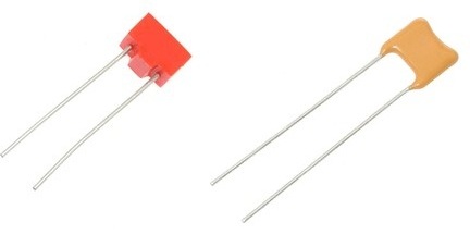
For example, types K10-7V, K10-19, KD-2, differ in a relatively large capacity (from 1 pF to 0.47 microfarads) with small dimensions. Their operating voltage ranges from 16 to 50 volts. Their features are: low leakage currents, low inductance, which makes them able to operate at high frequencies, as well as small size and high temperature stability of the capacitance. Such capacitors successfully operate in DC, AC and pulsed current circuits.
The tangent of the loss angle tgδ does not usually exceed 0.05, and the maximum leakage current is not more than 3 μA. Ceramic capacitors are resistant to external factors such as vibration with a frequency of up to 5000 Hz with acceleration up to 40 g, repeated mechanical shocks and linear loads.
Ceramic disc capacitors are widely used in power supply smoothing filters, in filtering noise, in interstage communication circuits, and in almost all electronic devices.
The markings on the capacitor body indicate its rating. Three numbers are deciphered as follows. If the first two digits are multiplied by 10 to the power of the third digit, then you get the value of the capacitance of this capacitor in pf. So, a capacitor marked 101 has a capacitance of 100 pF, and a capacitor marked 472 has a capacitance of 4.7 nF.
For example, K10-17A or K10-17B, unlike single-layer ones, have alternating thin layers of ceramics and metal in their structure. Their capacity is therefore greater than that of single-layer ones, and can easily reach several microfarads. The maximum voltage is also limited here to 50 volts. Capacitors of this type are capable, like single-layer ones, to operate properly in DC, AC and pulsating current circuits.

Able to operate at high voltages from 50 to 15,000 volts. Their capacitance is in the range from 68 to 100 nF, and such capacitors can operate in DC, AC or pulsed current circuits.
They can be found in line filters as X / Y capacitors, as well as in secondary power supply circuits, where they are used to eliminate common mode noise and absorb noise if the circuit is high frequency. Sometimes without the use of these capacitors, failure of the device can threaten human life.

A special type of high voltage ceramic capacitors - high voltage pulse capacitorused for powerful pulse modes. An example of such high-voltage ceramic capacitors are domestic K15U, KVI and K15-4. These capacitors are capable of operating at voltages up to 30,000 volts, and high-voltage pulses can follow at a high frequency, up to 10,000 pulses per second. Ceramic provides reliable dielectric properties, and the special shape of the capacitor and the arrangement of the plates prevent breakdown from the outside.
Such capacitors are very popular as circuit capacitors in powerful radio equipment and are very welcome, for example, by teslast builders (for designing on a spark gap or on lamps - SGTC, VTTC).

For example, K73-17 or CL21, based on metallized film, are widely used in switching power supplies and electronic ballasts. Their body made of epoxy compound gives the capacitors moisture resistance, heat resistance and makes them resistant to aggressive media and solvents.
Polyester capacitors are available in capacities from 1 nF to 15 μF, and are rated for voltages from 50 to 1500 volts. They are distinguished by high temperature stability with high capacity and small size. The price of polyester capacitors is not high, so they are very popular in many electronic devices, in particular in energy-saving lamp ballasts.
The marking of the capacitor contains at the end a letter indicating the tolerance for the deviation of the capacitance from the nominal, as well as a letter and number at the beginning of the marking, indicating the permissible maximum voltage, for example 2A102J - a capacitor for a maximum voltage of 100 volts, with a capacity of 1 nf, permissible capacitance deviation + -5% ... Tables for decoding the marking can be easily found on the Internet.
A wide range of capacitances and voltages makes it possible to use polyester capacitors in DC, AC and impulse current circuits.

Polypropylene capacitors, for example K78-2, unlike polyester ones, have a polypropylene film as a dielectric. Capacitors of this type are available in capacities from 100 pF to 10 μF, and the voltage can reach 3000 volts.
The advantage of these capacitors lies not only in the high voltage, but also in the extremely low tangent of the loss angle, since the tgδ may not exceed 0.001. Such capacitors are widely used, for example, in induction heaters, and can operate at frequencies measured in tens and even hundreds of kilohertz.

Deserve special mention starting polypropylene capacitorssuch as CBB-60. These capacitors are used to start AC induction motors. They are wound with a metallized polypropylene film on a plastic core, then the roll is filled with compound.
The capacitor body is made of non-combustible material, that is, the capacitor is completely fireproof and suitable for work in harsh conditions. Conclusions can be both wired and for terminals and bolts. Obviously, capacitors of this type are designed to operate at industrial mains frequency.
Starting capacitors are available in AC voltages from 300 to 600 volts, and a range of typical capacities is from 1 to 1000 μF.
Andrey Povny