To establish and test home-made electronic devices, radio amateurs use so-called dumping fees. Applying a dumping board allows you to check, establish and test the circuit before the device will be collected on the finished pCB.
This avoids errors when designing, as well as quickly make changes to the scheme being developed and immediately check the result. It is clear that bread boardOf course, saves a bunch of time and is very useful in a radio amateur workshop.
Progress and electronics development also affected the dumping fees. Currently, you can, without any special problems, purchase an inconceptuous battle fee. What are the advantages of such an insane dump truck? The most important plus of the inconvenient circuit board is the lack of the soldering process when making the scheme. This circumstance significantly reduces the process of maketting and debugging devices. Collect the scheme on an insane circuit board can be literally in a couple of minutes!
How does the bewildered dumping board work?
The inconception makeboard consists of a plastic base in which there is a set of conductive contact connections. There are a lot of these contact connections. Depending on the design of the dumping board contact connectors Combined in strings, for example, 5 pieces. As a result, a five-pin connector is formed. Each of the connector allows you to connect conclusions to it. electronic components or conductive conductors with a diameter, as a rule, not more than 0.7 mm.
But, as they say, it is better to see once than hear a hundred times. This is the looks like an inside EIC-402. For mounting without soldering by 840 points. Thus, this dampboard contains 840 contact connections!

The base of the bold fee - ABS plastic. Contact connectors are made of phosphorous bronze and coated with nickel. Due to this, contact connectors (points) are designed for 50,000 connection cycles / disconnection. Contact connectors allow you to connect radio components and conductors with a diameter of 0.4 to 0.7 mm.
But it looks like a debug board for the microcontrollers of the PIC series, assembled on an inconvenient dummy.


As you can see, the beam-free dummy board allows you to install resistors, capacitors, chips, LEDs and indicators. Incredibly easy and convenient.

With the help of an invisible dump truck, the study of electronics turns into a fascinating process. Circuit diagrams are collected on a layout without excess work. Everything is so simple as if you were playing with the LEGO designer.
Depending on the "steepness" of the beam-free bobbin, it can be equipped with a set of connecting conductor (wires-jumper), additional connections, etc. Despite all the "buns", the main indicator of the quality of the invasive dummy is still the quality of contact connections and their quantity. Everything is clear here, the more contact points (connections), the more complex scheme can be mounted on such a board. The quality of the connector is also important, because from frequent use, the connectors may lose their elastic properties, and this will lead to poor contact quality.
Since the dummy board connectors allow you to connect the conductors with a diameter of no more than 0.4-0.7 mm, then the attempts to "squeeze" thick conclusions of parts can only lead to the damage of contact. In this case, to the conclusions of radio elements having a sufficiently large diameter, for example, as in powerful diodes, it is better to solder or wind the wire of a smaller diameter and then connect the element to the dumping board.
If it is planned to make a sufficiently complex scheme with a large number of items, the area of \u200b\u200ban invisible dump truck may not be enough. In this case, it is better to divide the scheme to blocks, each of which needs to be assembled on a separate dealer and then connect the blocks into a single device using connecting conductors. It is clear that in this case there will be an extra damp.
As a rule, a dialing board with a set of connecting conductors of different lengths (wires-jumper) is more expensive than ordinary beamboatics, which are not equipped with such conductors. But it does not matter. As a connecting conductors, you can use the usual wire in isolation.
For example, perfectly suitable for such purposes is very common and affordable wire KSVV 4x0.4This is used to mount the security and fire alarm. This wire has 4 veins, each of which is covered with isolation. The diameter of the copper core without taking into account the insulation is 0.4 mm. Isolation from such a wire is easily removed with nipples, and the copper wire is not covered with lacquer coating.
From one meter of such a cable, you can make a complete residual conductors of different lengths. By the way, in the photographs of the dummy card shown above, the KSVV wire was used to connect radio components.
The bold fee should be protected from dust. If the layout is not used for a long time, then dust is settled on its surface, which clogs the contact connectors. In the future, this will lead to a bad contact and the layer will have to be cleaned.
Chimunical dumping fees are not designed to work with a voltage of 220 volts! It is also worth understanding that makting and verification of work high flow schemes There may be an overhearance of contact connections on an uncerexious.
Shielding of the dumping board.
Preparation of an invoking dumping fee before work.
Before starting to master the diagram on a new inclosable dummy card, it will not be "ringing" contact connectors by multimeter. It is necessary in order to find out which points-connectors are interconnected.
The fact is that the points (connectors) on the dumping board are connected on the dumping board in a special way. For example, the EIC-402 loature dummy has 4 independent contact zones. Two on the edges - these are the power tires (plus " + "And minus" - "), They are labeled with a red and blue line along the contact points. All tire points are electrically connected to each other and are essentially one conductor but with a bunch of point-connector.

The central region is divided into two parts. In the middle, these two parts shares a kind of groove. In each part 64 lines of 5 point connector in each. These 5 dot connectors in the string are electrically connected. Thus, if you install, for example, a chip in the DIP-8 or DIP-18 housing in the center of the dummy board, then either of its output can be connected either 4 outputs of radio elements or 4 jumper connecting conductor.

Also, a power bus on both sides of the dump truck will also be available for connecting. It is quite difficult to explain this. Of course, it is better to see this live and plentyful macatetie. Here I assembled this scheme on an invoko board. This is the simplest debugging board for PIC series microcontrollers. It has a microcontroller PIC16F84 and the strapping elements: indicator, buttons, buzzer ...

Mounting fee for installation without soldering is convenient to use for a quick assembly of measuring circuits, for example, to check the IR receiver.
Such fees can be purchased not only on the radio rolls, but also buy on the Internet.
Cheap covertoam can be purchased on Aliexpress.com. On how to buy radio components and sets on Aliexpress, I told.
Often to quickly assemble a layout of any electronic circuit on the table, it is convenient to use the dump truck, which allows you to do without soldering. And only then, when you see for the performance of your scheme, you can take care of the creation of a circuit board with soldering. For a person, only a beginner to know the world of electronics, it is not obvious to the use of such a tool as a breadboard or Bradboard (Breadboard). Let's see what is a batch fee and how to work with it.
Instructions for working with an invoko dumping board (Braddatrad)
We need:
- Breadboard, buy;
- connecting wires (I recommend this set);
- lED (you can buy);
- resistor resistance 330 Ohms or close to this (a great set of resistors of all popular denominations);
- croon type battery for 9 volts.
1 Descriptionmacateboards
Macateboards there are many types. They differ in the number of conclusions, the number of tires, configuration. But all of them are arranged according to one principle. The dumping board consists of a plastic base with a plurality of holes located usually with a standard pitch of 2.54 mm. With the same step, legs are usually located at the output chip. Holes are needed in order to insert the findings of radio elements or connecting wires. A typical view of the dumping board is presented in the figure.
Various types of breadboard
His British name - Breadboard ("Bread Board") - This type of boards received due to comparison with a bumping board: it is suitable for quick "preparation" of simple schemes.
Also there are baked feet. They differ in the fact that they are usually made of fiberglass, and their metallized platforms are well suited for soldering wires and output radio elements. In this article, we do not consider such fees.
2 Devicemacateboards
Let's see what inside the batade. The figure below shows a general view of the board. On the right side of the picture, the conductor tires are indicated. Blue colour - this is "minus" schemes, red - "plus", green - these are conductors that you can use at your discretion for parts connections electrical circuitCollected on the Male Plate. Please note that the central holes are connected by parallel rows of the pale board, and not along. Unlike the power tires, which are located along the edge of the dummy board along its edge. As can be seen, there are two pairs of power tires, which allows you to apply two on the fee different stresses, for example, 5 V and 3.3 V.
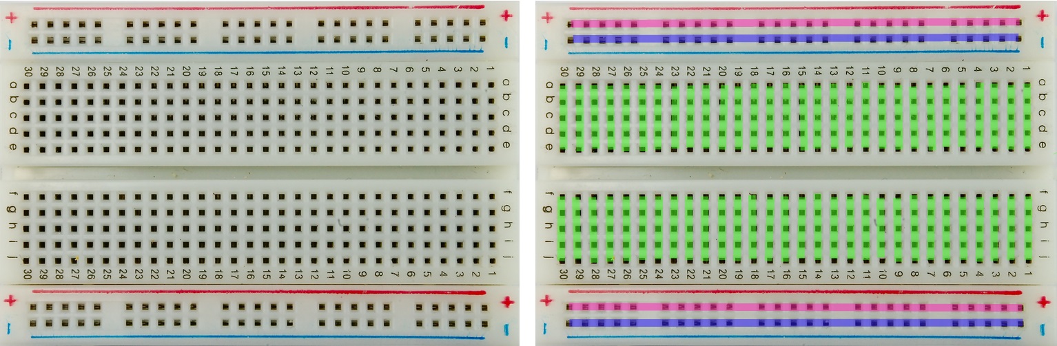 Device of the Make Plata (Breadboard)
 Two groups of transverse conductors are separated by a wide groove. Thanks to this deepening, chips in DIP-enclosures can be placed on the dump fee (housings with "legs"). As in the figure below:

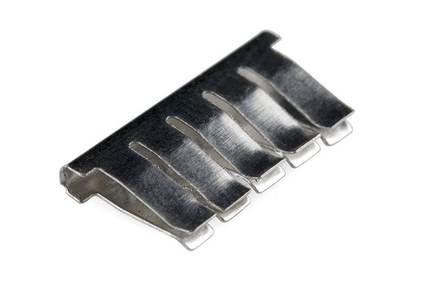
There are also radio elements for surface mounting (their "legs" during installation is inserted out not in the holes in the printed circuit board, but solder directly to its surface). It is possible to use them with a similar dealer only with special adapters - clamping or under the soldering. Universal adapters are called "zero-gain panels" or Zif panel using foreign terminology. Such adapters are most often under 8-pin chips and under 16-pin chips. An example of such elements and such an adapter is shown in the illustration.

The numbers and letters on the dumping board are needed so that you can easier to navigate on the board, and if necessary, draw and sign your own concept. It can sometimes be useful when installing large schemes, especially if you mount the description. To use them in about the same way as letters and numbers on a chessboard, for example: connect the output of the resistor into the nest E-11, etc.
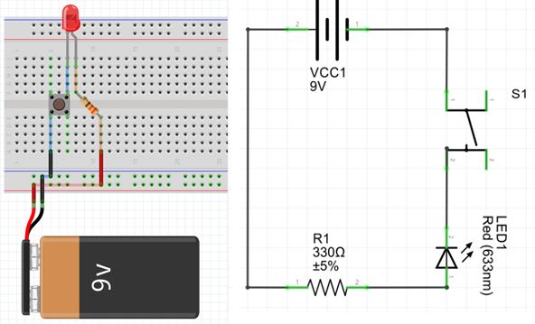
3 Collect the schemeon a dumping board
To acquire the skill of working with a batch fee, we collect the simplest scheme as shown in the figure. Plus batteries by connecting to the plus tire of the dummy board, "minus" - to the negative tire. Bright red and black lines are connective wires, and pale translucent are connections that provide a bold board, they are shown for clarity.
If the first part of the article focuses on the overview of the bias and the description of their device, then now consider some useful subtleties and nonsions that you need to know when working with such dumping fees.
If the Instructions of the Inpaid Macate Fee says that the diameter of the wire inserted into contacts is 0.4 - 0.7 mm, then you should not try to insert the findings of parts that the thickness of the specified value. This will bring to weaken and wear contacts. If there is a need to apply such parts, then it is better to roll to the thick conclusions of the wire of the specified diameter, or simply wrap. Naturally, the wire must be without isolation.
Clearchy dump trucks are sold in two configurations: with wires - jumpers and without them. In the first version, the fee is obtained somewhat more expensive, but not at all troubles, if you managed to buy a single fee, - you can always adapt anything.
The switching wires, of course, are sold separately, but if there is no desire or to buy them, it is quite suitable for the KSVV 4 * 0.4 Wire, used for mounting.
Such a wire contains 4 insulated veins with a diameter of just 0.4 mm. Isolation from the wire is easily removed by rake or knife, and the residential veins do not have a varnish coating.
In case of the need to make a complex device, its individual functionally completed parts are better to collect on separate sizes of small sizes, after which it is from the obtained nodes to collect the entire design.
Sometimes it happens that one device is not yet collected, but for some reason it is necessary to urgently assemble another, completely new. And here it begins! It is necessary to disassemble the collected, not yet debt scheme, which, then, may have to be collected again. But the only irreplaceable resource is the time that is lost on these meaningless assemblies - disassembly. Therefore, it is better not to notice, but to acquire several dumping boards, it will go faster.
 We should not forget that the bold fees are designed for low-current equipment - and. Therefore, in no case in any case, it is unacceptable to supply network voltage on them - 220 V. It can lead to overheating of contacts and a breakdown of isolation, and what will happen after that everything is probably known.
But even in transistors and chips, a short circuit may occur, which will cause overheating of these elements, will lead to the heating of contacts and melting the plastic base of the board. Therefore, when you first turn on the circuit, it is desirable to measure the current consumed or at least check the temperature of all elements with a finger.
General rule, not only for dumping boards. First, components are installed not exposed to static electricity:, and.
In addition to the details, connective wires are installed on the dumping board. Connecting wires are better installed with tweezers or small pliers. With these tools to conduct and disassemble the wires.
As in all such cases Check the board on the correct installation, on the absence of short circuits or non-contacts. Unused conclusions by chips do not leave "hanging in the air", and connect either to a common wire or to the power bus. Free inputs will lead to the appearance of such elements, simply no interference, which will be distributed throughout the circuit and its adjustment will be much more problematic.
 Probably, it will have to be noted here that the dumping fees have a large fitting capacity due to long connecting wires, as well as many contacts. Therefore, too high-frequency schemes on such fees will work badly, and may not be completely.
To avoid the influence of long conductors, it is desirable to shut nutrition conclusions by microcircuit ceramic condensers Small capacity, as is done on printed circuit boards.
Checking the installation of the installation, you can use "oak" chips TTLwhich are practically not sensitive to statics. You can, of course, do without them, but it is not very convenient to overtake the cream of the multimeter into the holes on the board, it is more convenient to touch the legs of the chip. After completing the inspection and eliminating the inaccuracies, "training" chips should be replaced by real.
When using the CMOS structure chips to protect against statics, the use of antistatic grounding bracelets is very desirable. If there are no such available, you can recommend the use of a wire washcloth for washing pan. Such a mustache has the shape of a ring where you can push your hand. With the help of a flexible wire through a resistor resistance to no more than 1m connected to grounding.
After checking the circuit, you can insert the CMOS microcircuits mentioned in the fee. When setting up the scheme, replacing parts, or making changes, the protective antistatic bracelet is better not to remove.
Macateboards can be collected for any device. They are popular with novice electrical workers and experienced masters. They are collected with soldering and without soldering. The first durable and can be used as the main fee, and the second are more comfortable in assembly due to the exclusion of soldering works.
To start the production of any product, it is necessary to make it layout, and then, appreciating the productivity of the product and its other parameters, proceed to the release of the series. In this case, you save money and time. But the prototypes are made not only in production, they are also widely used in electronics and, first of all, this is due to the release of dummy cards.
Suppose you are going to make a new electronic device. Previously, the prototype of the bold fee was the appearance of a rectangle from the cardboard, in which the holes were made and the radio elements connecting between themselves were inserted there, and then its work was checked. If the functioning of the device occurred normally, the production of the main board began using the appropriate materials. Now the task is somewhat simplifiable - the market is actively sold by bias with already prepared holes and tracks, which can be found in specialized stores, for example, in this http://makerplus.ru/, where you can choose the appropriate option.
What bold fees are
Macateboards are made without soldering and soldering. The design without soldering is a plastic housing with numerous holes with contact connectors. Details are mounted in them. Holes are designed for wires with a diameter of 0, 7 mm. The distance between them is 2, 54 mm, this is enough to install the transistor and other elements.
Power tracks are designated blue and red lines. The number of points for connectors may vary from 100 to 2500 pieces. The principle of working with such a board is simple. You mount the electronic elements in the desired holes and connect them with regular wires, or buy specially prepared wire jumpers. If the scheme is collected incorrectly, then you disassemble it and install it again.
Soldering
This board differs from the above option that the elements installed in the housing can be soldered. In this case, you can use it not only as a layout, but also as a real product. True, then the fee will have several large sizes. In addition, soldering structures have a lower price.
Boards with soldering, which, by the way, can be purchased on the page of the online store http://makerplus.ru/category/breadboard, have holes for wires with a diameter of up to 0.9 mm and are located in one-inch increment (2, 54mm). On the one hand, the design is located straight insulated foil lines, and the radio elements and jumpers are installed on the other.
- Immediately cut the board to the desired size. For this, conventional scissors, cutter, hacksawa are suitable. You can even just break her over holes, but then checking the edges.
- If you are not going to use the board right now, then do not touch the places with the foil once again. Hands can be wet, which will lead to corrosion of the surface and deterioration of contact.
- If oxides or contamination take place, then clean them with zero sandpaper or ordinary eraser.
- Radio elements are installed from the side where there are no strips from foil. The conclusions are populated into the holes and searched from the reverse side.
- Blue color conductive tracks denotes "minus" schemes, red "plus", and green is used at their discretion. The tracks are marked with the same side where the foil is located.
- The most important positioning of parts occurs in a vertical position, since in this case the error will lead to an incorrectly assembled chain.
Consider that the bikes of both types can have a groove on the sides. It is necessary for those who collect big deviceconsisting of several modules. The grooves allow you to collect one large fee of several small.
For designing and debugging prototypes various devices Macateboards are used on Arduino (the other name is incremental circuit board and Breadboard). They are several varieties and differ in size and some other constructive features. Breadboard Macateboards can help as novice engineers to create simple schemesand when macating complex devices. What is a miscellaneous board and how to use this adaptation will tell this article.
Rarely what real project Arduino. Contains less than 5-10 elements interconnected. Even in a simple well-known well-known chart of the beacon, 2 elements, a LED and a resistor, which must be somehow connected to each other are used. And then just the question arises of how to do it.
To date, there are the following main installation methods that are used in electronics and robotics at the stage of creation of prototypes:
- Soldering. For this, special fees with holes in which the parts are inserted and are connected to each other soldering (using the soldering iron) and jumpers.
- Cheat. According to this technology, the contact connections of devices are combined with a batch board using a clean wire winding to a pin contact.
The most advanced option for the creation of prototypes is an invaluable dump truck, which has undoubted advantages:
- The ability to conduct debugging work a large number of times by changing the modification of the schemes and methods for connecting devices;
- The ability to connect multiple boards into one large, which allows working with more complex and large projects;
- Simplicity and speed of creating prototypes;
- Durability and reliability.
English version of the name of the bewilderous dummy - Breadboard.
Diagram of the Mackety Plata
To know how to use the dealer, it is necessary to understand the principle of its device.
A package for mounting without soldering has a plastic base with a plurality of holes (the standard distance between them is 2.54 mm). Inside the design there are rows of metal plates. Each plate has clips that are hidden in the plastic part of the installation.
Turning on the wires is performed in these clips. When the conductor is connected to one of the individual holes, the contact simultaneously connects to all other contacts of the individual.
It is worth paying attention to that one rail contains 5 clips. it general standard For all covertuous boards. That is, each rail can be connected to five elements, and they will be interconnected.
It should be noted that although there are ten holes in each row, they are still divided into two isolated parts, five each. There is a rail between them without pins. This design is necessary for insulation of plates from each other, and allows you to simply connect chips made in DIP-enclosures.

Some dummy cards also include two lines of food from each side. Usually the "red line" is used to supply "+" voltage, "blue" - for "-". Due to the presence of two power tires, two different voltage levels can be fed on the fee.
To simplify the orientation on the batch, digital and letter notation are also applied, which can be guided by creating, for example, an instruction for connecting.
Main types of misses
Macateboards differ in the number of conclusions located on the panel, tire number and configuration. There are also dummy cards in which contact compounds are performed by soldering, but it is more difficult to work with them than with covertuous devices.
Depending on the characteristics, these species are the most common:
- For the assembly of large microcircuits, inside 830 or 400 holes are mainly used. To connect several components and supply of wires to the necessary points - by 8, 10, 16 holes;
- With the presence of grooves for the clutch of boards that allow you to implement sufficiently large projects;
- With self-keys based on reliable fastening on the device;
- With applied on the fee for connecting devices.
Depending on the cost and manufacturer, optional accessories can be included in the package - jumpers, a variety of connectors. But the main quality criterion always remains the number of contact connectors and their technical characteristics.
How to use a bullshit
It's easy to use a dealer. When creating a circuit in the holes on a plastic case, the necessary elements are inserted - capacitors, resistors, various indicators, LEDs, etc. The width of the connectors allows you to connect the conductors to the contacts with a cross section from 0.4 to 0.7 mm.
The simplest example of creating a prototype schema using a batch fee can be this embodiment:
For its assembly you need to take:
- Breadboard;
- wires for connecting;
- 1 LED;
- clock button;
- resistor with a nominal resistance of 330 ohms;
- battery type "Crohn" on 9V.
Plus the batteries connect to the plus tire, and minus to the negative. If the scheme is assembled correctly, then when you press the button, the LED lights will be ensured.
Attention! Effective dumping fees are absolutely unacceptable to use with a voltage of 220V!
BreadBoard breadboard are optimal for creating almost any digital circuits and are not intended to build analog circuits, with high sensitivity to the size of the resistance. In their practice, they are often used as newcomers, knowing the foundations of circuitry, and experienced professionals due to the simplicity of installation and high Quality Connections of work contacts.