The first time I came across Peltier elements (EP) several years ago, when I developed water cooling device in aquarium. Today, EPs have become even more affordable, and their scope has expanded significantly. For example, in water coolers, which can often be found in offices, are used EP. There they are in the shape of a 4x4 cm square (Fig. 2)with the help of special thermal paste and coupling screws are fixed between the cooling radiator and the body of the water tank, the “cold” surface to the tank. Other EPs are also common.
Fig. 2 Peltier Element
Basically work Peltier element lies the effect discovered by the French watchmaker Jean Peltier. In 1834, Peltier discovered that when direct current flows in a circuit consisting of dissimilar conductors, heat is absorbed or released in the places of contacts (junctions) of the conductors (depending on the direction of the current). The degree of manifestation of this effect largely depends on the materials of the selected conductors and is proportional to the passing current. The Peltier element is reversible. If a temperature difference is applied to it, current will flow in the circuit.
The classical theory explains the Peltier phenomenon by the fact that the electrons transferred by the current from one metal to another are accelerated or decelerated by the internal contact potential difference between the metals. In the first case, the kinetic energy of electrons increases, and then is released in the form of heat. In the second case, the kinetic energy of the electrons decreases, and this decrease in energy is replenished due to the thermal vibrations of the atoms of the second conductor. As a result, cooling occurs.
The Peltier effect is most strongly observed when usingsemiconductors (p- and n-type conductivity). Depending on the direction of the electric current through the pn junctions, due to the interaction of the charges represented by the electrons (n) and the holes (p) and their recombination, the energy is either absorbed or released.

Fig. 3 Peltier effect
Peltier effect underlies work thermoelectric module (TEM). A single TEM element is a thermocouple consisting of one p-type conductor (branch) and one n-type conductor. When several such thermocouples are connected in series, the heat (Q c) absorbed at the n-p type contact is released at the p-n-type contact (Q h). As a result, heating (T h) or cooling (T c) of the portion of the semiconductor directly adjacent to the pn junction occurs(fig. 3), and there is a temperature difference (AT \u003d T h -T c) between its sides: one plate is cooled and the other is heated. Traditionally, the side to which the wires are attached is hot, and it is depicted from below.

Fig. four
The thermoelectric module is a combination of such thermocouples (Fig. 4),usually interconnected in series in current and in parallel in heat flow. Thermocouples are placed between two ceramic plates (Fig. 5).Branches are brazed onto copper conductive pads (busbars), which are attached to special heat-conducting ceramics, for example, from oxide

Fig. 5 Thermoelectric Peltier module
aluminum. The number of thermocouples can vary over a wide range (from several units to several hundred), which makes it possible to create TEMs with a cooling capacity from tenths of a watt to hundreds of watts. Bismuth telluride has the highest thermoelectric efficiency among industrially used materials, in which special additives (selenium and antimony) are added to obtain the required type and conductivity parameters.

Fig. 6
Typical module (Fig. 6)provides a significant temperature difference, which is several tens of degrees. With appropriate forced cooling of the heating surface, the second cooler surface allows negative temperatures to be reached. To increase the temperature difference, cascade inclusion of Peltier thermoelectric modules is possible (Fig. 7)while ensuring their sufficient cooling. Peltier-based cooling devices are often referred to as “active Peltier coolers” or simply “Peltier coolers”.

Fig. 7, cascading Peltier thermoelectric modules
The use of Peltier modules in active coolers makes them more efficient than standard coolers based on radiators and fans. However, in the process of designing and using coolers with Peltier modules, it is necessary to take into account a number of specific features arising from the design of the modules and their operating principle.
Of great importance is the power of the Peltier module, which, as a rule, depends on its size. A low-power module will not provide the necessary cooling, which can lead to disruption of the protected element due to overheating. However, the use of modules with too much power can cause the temperature of the cooling radiator to drop to

Fig. 8, active cooler, based on a semiconductor Peltier module
moisture condensation from the air, which is dangerous for electronic devices. Peltier modules emit a relatively large amount of heat during operation. For this reason, a powerful fan should be used as part of the cooler. Fig. 8an active cooler is shown in which a Peltier semiconductor module is used.
The voltage supplied to the module is determined by the number of pairs of branches in the module. The most common are 127-pair modules, the maximum voltage for which is approximately 16 V. But these modules are usually supplied with a supply voltage of 12 V, i.e. approximately 75% U max. Such a choice of supply voltage in most cases is optimal: it allows to provide sufficient cooling power with acceptable efficiency. With an increase in the supply voltage of more than 12 V, the increase in cooling power is insignificant, and the power consumption increases sharply. With decreasing supply voltage, profitability increases, since refrigeration capacity also decreases, but linearly.
Table 1 peltier element, characteristics
|
Module type |
Characteristics |
||||
|
I max, A |
U max, B |
Q max, W |
Sizes, mm |
||
|
A-TM8.5-27-1, 4 |
| 15,4 |
72,0 |
40x40x3.7 |
||
|
A-TM8.5-127-1.4HR1 |
15,4 |
72,0 |
40x40x3.4 |
||
|
A-TM8.5-127-1.4HR2 |
15,4 |
72,0 |
140x40x3.7 |
||
|
A-TMb. 0-127-1,4 |
15,4 |
53,0 |
40x40x4.2 |
||
|
A-TM6.0-127-1.4HR1 |
15,4 |
53,0 |
40x40x3.8 |
||
|
A-TM6.0-127-1.4HR2 |
15,4 |
53,0 |
40x40x4.2 |
||
|
A-TMZ, 9-127-1.4 |
15,4 |
35,0 |
40x40x5.1 |
||
|
A-TMZ, 9-127-1,4HR1 |
15,4 |
35,0 |
40x40x4.8 |
||
|
A-TMZ, 9-127-1.4HR2 |
15,4 |
35,0 |
40x40x5.1 |
||
|
A-TM3.9-127-1.4 |
15,4 |
34,0 |
30x30x3.9 |
||
|
A-TMZ, 9-127-1,4HR1 |
15,4 |
34,0 |
30x30x3.9 |
||
|
A-TMZ, 9-127-1.4HR2 |
15,4 |
34,0 |
30x30x3.9 |
||
|
A-TM37.5-49-3.0 |
37,5 |
130,0 |
40x40x4.3 |
||
|
A-TM37.5-49-3.0HR1 i |
15,4 |
72,0 |
40x40x4.3 |
||
|
A-TM6.0-31-1.4 |
3,75 |
12,5 |
20x20x4,2 |
||
|
A-TM6.0-31-1.4HR1 |
3,75 |
12,5 |
20x20x4,2 |
||
Note: modules marked HR1 and HR2 are highly reliable.
For modules with a different number of branch pairs (other than 127), the voltage can be selected according to the same principle: 75% of U max, but it is necessary to take into account the features of a particular device, first of all, the conditions of heat removal from the hot side and the possibility of power sources. For example, it is recommended to supply voltage from 12 to 18 V. to modules of the DRIFT series (199 thermoelectric pairs)
During operation, reliable thermal contact between the heat exchanger and the radiator is important, so the TEM is attached using thermally conductive paste (for example, KPT-8). If there is no special thermal paste, you can successfully apply the pharmacological agents purchased at the pharmacy, for example, Lassari paste or salicylic-zinc paste.
Since the maximum temperature on the hot side of the TEM reaches + 80 ° C (in high-temperature coolers from Supercool - + 150 ° C), it is important that the EA cools correctly. The hot surface of the TEM should be facing the radiator, on the other side of which a cooling fan is installed (air flow is directed from the radiator). The fan and TEM in accordance with the polarity are connected to a power source, which can be the simplest: step-down transformer, rectifier on diodes and a smoothing oxide capacitor. But the ripple of the supply voltage should not exceed 5%, otherwise the efficiency of the TEM decreases. It is better if the fan and TEM are controlled by an electronic device based on a comparator and a temperature sensor. As soon as the temperature of the cooled object rises above the set threshold, the cooler and fan are automatically turned on and cooling starts. The degree of cooling (or heating) is proportional to the current passing through the TEM, which allows you to accurately control the temperature of the “serviced” object.
Thermoelectric modules are sealed so that they can be used even in water. Ceramicthe surface of the TEM is polished, black (“-”) and red (“+”) wires are soldered to the lamellas (leads). If the TEM (Fig. 2) is positioned with the leads to itself so that the black wire is on the left and the red wire is on the right, the cold side will be on top and the hot side below. Marking is usually applied on the hot side.
Table 2
|
Impact temperature, 0С |
Location of exposure (side 1 or 2) * |
Exposure time, sec |
Resistance (after the exposure time), kOhm |
|
Constant |
|||
|
Lighter heating |
|||
|
Lighter heating ** |
>2000 |
||
|
5 (in the refrigerator) |
|||
|
20 (outdoors in winter) |
|||
|
36 after cooling in the refrigerator (-5) |
|||
|
36 after cooling outside (-20) |
|||
|
100 (boiling water) |
|||
|
Fire chamber of the Russian stove (open flame) |
0,06 |
Notes:
* - side 1 - side with the marking, side 2 - the reverse side (relative to the marking).
** When the back side was heated for 4 with a lighter with an open flame touching the surface of the RF, a current of 200 μA was detected at the terminals.
The most "running" types of Peltier modules are single-stage modules with a maximum power of up to 65 W (12 V) and 172 W (24 V). The designations of the modules are deciphered as follows: the first number is the number of thermocouples in the module, the second is the width of the sides of the branch (in mm), and the third is the height of the branch (in mm). For example, TV-127-1.4-1.5 is a module consisting of 127 pairs of thermoelectric branches, the dimensions of which are 1.4x1.4x1.5 mm. The dimensions of the modules are 40x40 mm, the thickness is about 4 mm. Standard single-stage modules are available with maximum power up to 70 W (12 V) and 172 W (24 V). Typical TEM parameters are given intable 1.
Table 3 Thermoelectric generator parameters

Fig. 9 thermoelectric generator
In experiments with TEM, I checked the change in its resistance in different modes. The tester M830 was connected to the conclusions (lamellas) of the module in the resistance measurement mode. The results are summarized in table 2.When the temperature effect was greater than room temperature on the side of the TEM with the marking, its resistance decreased, on the reverse side it increased proportionally (lines 2 and 3 of the table show the reaction to the edge of the palm touching the surface of the TEM, the temperature is indicated at about 36 ° C).
Considering reversibility of Peltier elements, based on them, you can develop power sources. For example, thermoelectric generatorThe “B25-12 (M)” of the Krioterm company (Fig. 9) allows you to charge the batteries of mobile phones, digital cameras, watch TV, work on a laptop for a long time, etc. The only requirement is that you need a heated surface measuring 20x25 cm. The generator parameters are given attable 3.
A. Kashkarov.
Peltier elements - it would seem, is no longer news, but many do not fully understand the principle of their work, and do not know what can be made from modules and why they are needed. Inventor Igor Beletsky will show some visual experiments so that you have an understanding of what these records are capable of.
They are easy to purchase on the Internet and order delivery by mail. It is best to buy Peltier at this Chinese store. There is also a special cooling cooler.
Peltier module (element)
The most popular among practitioners keen on ideas of free natural energy and manufacturers of technical devices is an element with a size of 40 by 40 millimeters with a marking. This means that it consists of 127 pairs of tiny thermocouples - semiconductors of various types, which are paired with copper jumpers in a series circuit and are designed for direct current up to 5 A at a voltage of 12 volts.

Some people think that Peltier modules are something like solar panels - because they are the same flat, stick out wiring, and both of them can generate electric current. Alas, this is not entirely true. To understand how the mysterious records function, watch the video of I. Beletsky, a description in text format below.
Pelt and Zebek effects - module functions
This device has as many as two operating modes - 1. the generation of cold and heat; 2 - electric current generation.
1. So famous peltier effect (warm and cold). This is when you bring a constant current to the element and notice that one of its sides has become warmer and the other colder. Thus, it works like a heat pump. Very useful property. No doubt about it.
2. But it turned out that the reverse process takes place - the so-called zebek effect, namely, the occurrence of an electric current when establishing and maintaining a certain temperature difference on the sides of the module itself (plate).
Note. Never overheat elements if you want to continue experimenting with them. The semiconductors in the module are soldered by solder, the melting temperature of which can lie in the range from eighty to two hundred degrees. And considering where most of these elements are manufactured today, one can only guess on what nozzles they were soldered.
Scheme. How electricity is generated by heating the Peltier sides


The whole trouble is that this element will work normally only with effective cooling.
Electricity test
For example, we want to test the Zebek effect. Put a mug of boiling water on top. Thus, 100 degrees allowed for heating are not exceeded.

We observe the appearance of tension. Interestingly, if you change the direction of the heat flux through the module, then the direction of the direct current will change. But over time, on the second side, due to the thermal conductivity of the Peltier element, the temperature will also rise and the voltage will naturally drop.
For the effect to be permanent, constant heat removal is needed. For this, the module is placed on a massive radiator and preferably with active cooling. The indicators are clearly better, as you understand. This requires additional energy.
Let's say you want to make camp charging for mobile phones out of this element. Then, in nature, the radiator can be placed in cold water, possibly even flowing or icy, which is undoubtedly even better. The use of these modules in the winter with a good free minus is the most promising.
True, one element for charging the phone will obviously not be enough. But two is better. Naturally, if you increase the heating, then the output power will also increase. But this is a very risky step that can only be done for the sake of experiment. The operation of such a generator will not last long.
Now we turn to the Peltier effect, that is, to the production of cold.
Pelt Modules Refrigerator - How Effective Is It?
For the experiment, a car refrigerator will be used. Useful volume of its 20 liters. Please note - the declared power is 48 watts at a current of 4 amperes and a constant voltage of 12 volts. This means that inside there is only 1 small Peltier element. For those who are not on the topic, let’s reveal a secret - an ordinary home refrigerator, the size of which is many times larger, has the same power. Well, okay, now is not about that. Check its effectiveness. For example, we set it the minimum task to cool a glass of water with a room temperature of 26 degrees. For the operation of the refrigerator, we will use a power supply that is ideally suited for its parameters. Additionally, a wattmeter will be placed in the circuit. It will display current, voltage and power in real time. But the most important thing is consumption, the so-called watt per hour. Thus, we can approximately estimate the energy consumption of our refrigerator.
Turn on and see, everything works great. Here is a current of 4.29 A. The voltage is 11.15 Volts. Power 47.9 watts. 0.1 Watt-hours.
While the process is going on, we will conduct a more visual experiment that will show what exactly happens in the refrigerator. When we apply a constant current to the element, it will begin to pump heat from one side to the other.

By the way, if you change the direction of the current, the direction of heat transfer will also change, which is very convenient. The main thing is not to forget about active cooling, because fifty watts of electrical power heats the element instantly. The more efficiently we remove heat from the hot side, the colder the other.
As you can see, on the very surface of the module, water freezes very quickly, well, it would be so much energy.

But back to our refrigerator. After one hour of operation, the air temperature inside dropped to fifteen degrees, and at the water dropped to 20. It was surprising that in an hour of operation he ate clearly 48 watts. Two hours later, the air had 13 degrees, and the water had 17. Finally, after three hours of operation, the air temperature stopped at 13 degrees, and in a glass of water it was 15 and below 12 it will not drop. Well, so-so refrigerator, given that it was not full of drinks. But at the same time, this monster consumed 140 watts. For a home network, it may not be much, but for a car battery this is already quite noticeable. Therefore, there is only one element. Because no more battery just pulls. And this means that the efficiency of such a module is negligible - literally a few percent, which again depends on the manufacturer. Such a refrigerator is more like a good thermos. If they had taken cold food from home, then he would simply not have allowed them to heat up quickly. Making such refrigerators large is energetically disadvantageous.
When is Peltier effective?
By the way, this also applies to home-made people trying to make automobile air conditioners on this principle. There are more efficient technologies, but using Peltier elements to cool something small and compact is just the perfect solution. There is a whole range of such devices, for example, cooling processors or microcircuits of various small-sized devices. This is most likely the most important plus of such elements. They are miniature and minimal in weight. Compared with the same photocells, Peltier certainly has more minuses, but the effect itself certainly deserves attention. In the end, it all depends on the tasks being solved, and if the energy is free, then a high efficiency is not so important.
How many degrees can an element be cooled? About it .
Conclusion
Peltier modules, popular among radio amateurs and engineers, are electronic elements that are actively used for cooling and generating electricity. On their basis, power sources are developed for lighting or charging devices in camp conditions, mobile compact refrigerators for cars. There are attempts to use for cooling computer processors. The operation of the devices is based on 2 mechanisms: when one side of the Peltier plate is heated and the second is cooled, an electric current is generated; when electricity is supplied to the contacts, one side of the plate is cooled, the other is heated.
The number of electronic devices in the world is constantly growing like a snowball. All of them consume electricity, and people have to constantly carry and carry batteries or produce it on bulky devices. As not so long ago, Peltier modules began to be used - elements that form an electric current when creating a temperature difference on their opposite sides.
Peltier and Seebeck effects
Despite the fact that the first Peltier element was created almost 2 centuries ago, the principle of operation found application only now, when suitable materials and the need for use appeared. It consists in the heat release at the contact of dissimilar conductors when an electric current flows through them. When the polarity changes, the contact area begins to cool. The process is reversible: when the temperature difference is artificially maintained, an electric current flows through the contacts of the conductors in their circuit (Seebeck effect).
Based on two thermoelectric effects, a Peltier module was created, the elements of which are located between two parallel ceramic plates in the form of heterogeneous conductors. The passing current through the contact of the conductors is the same, and the energy flows in each of them are different. When more energy comes into contact than flows out of it, this means that the electrons are inhibited in the transition region, causing it to heat up. When the polarity changes, the electrons accelerate, taking energy from the crystal lattice, which causes its cooling.
The Peltier effect is especially active at the boundaries of semiconductor elements, where the highest energy processes.
Thermoelectric module
Peltier elements are used in a device consisting of many semiconductors of p and n types. Unlike transistors and diodes, transition regions are located at the metal – semiconductor interface. In the Peltier module, elements are located in large numbers between ceramic plates, which makes the device more powerful.

Each element contains 4 transitions on the semiconductor-metal contact. When the electric circuit is closed, the electrons move from the minus of the battery to the plus, passing through all the transitions.
At the first transition of the thermoelectric module (TEM) between the copper bus and the p-semiconductor, heat is released in the latter, since the charge flow enters the region with lower energy.
At the other contact, energy is absorbed in the semiconductor, because the electrons are "sucked out" by an electric field that coincides with the direction of their motion. There is a cooling process.
At the third contact, the electron energy is absorbed, since an n-type semiconductor has more energy than metal.
At the fourth transition, heat is generated, since the electrons are again inhibited by the electric field.
Thus, heat is generated on one side, and the other is cooled. On one element, this phenomenon will be imperceptible, but the Peltier module, whose elements are located between two ceramic plates, creates a significant temperature difference.
The module can be used as a generator of electricity, if you maintain different temperature plates. In addition, each Peltier thermoelectric element is connected in series to the neighboring one through copper jumpers, and their currents are summed.

Advantages and disadvantages
Advantages of TEM:
- small sizes;
- reversibility of the process;
- use as an electric generator or refrigerator.
The disadvantages of TEM include high cost, low efficiency (not more than 3%), high energy consumption and the need to maintain a temperature difference.
Peltier refrigerator
The Peltier element for cooling the processor is more effective than standard elements. At the same time, the latter remain, but are used only to remove heat from the confined space of the computer.

When designing them as a cooler of electronic means, the following features should be considered.
- Power is directly related to the size of the module. Small devices will not create the required level of cooling. For example, they will not provide normal temperature conditions for the processor. An overly powerful module causes moisture to appear, which causes short circuits in the electronics, since the distances between the conductive elements on the printed circuit boards are small.
- Peltier modules themselves need to be cooled by fans and radiators, since they emit a lot of heat. This is necessary to reduce the temperature in the confined space of the computer and normalize the working conditions of other elements.
- The Peltier module is an additional load in the power supply.
- After failure, the refrigerator is an insulator between the radiator and the element to be cooled, which can lead to a quick failure of the latter from overheating.
- Modern processors can change the energy consumption during operation, which favorably affects the heat balance, but not always when using Peltier modules. The simplest refrigerators are designed for continuous operation, and they are not recommended for use with cooling programs.
Heat release
The cooling effect of TEM is small, and it produces a lot of heat. When it is used in the system unit, the inside temperature rises significantly, affecting the operation of the rest of the equipment. Additional means to reduce it are fans and radiators that create thermal exhaust.
The thermal mode of the module must be correctly calculated so that there is no overheating and condensation does not form on the electronic circuit boards. The Peltier cooler is selected with optimal power, where it is important to ensure the correct ratio of the temperature inside the case, the cooling object and air humidity.
Peltier Element: Characteristics
TEM is selected by thermoelectric parameters.
The calculation of power is as follows.
- The maximum allowable voltage U max (V) is selected and the maximum current I max (A), which flows through the Peltier module, is found from the U (I) plot. It is important here that its value be within the limits of the growth of the temperature difference versus current dT (I) \u003d T h - T s.
- According to the set value I, the characteristic dT (Q) is selected, where Q is the thermal power of the cooled element.
- From the known values \u200b\u200bof dT and T h, T c \u003d T h - dT is determined.

The characteristics of dT (Q) show that with an increase in the released heat power, the difference dT decreases. It can be done more by increasing the current through the module, which, in turn, should be limited.
Calculation Example
Initial data: U \u003d 12 V, Q s \u003d 60 W and T h \u003d 50 ° C.
At a voltage of 12 V, according to the characteristic U (I), we find the current I \u003d 5 A.
For a current of 5 A, the temperature difference is dT \u003d 4 K. Then T c \u003d T h - dT \u003d 50 - 4 \u003d 46 ° C.
By taking a more powerful module, you can increase dT. For a 131 W module, where I max \u003d 8.5 A, U max \u003d 28.8 V and an object with a heat generation capacity of 60 W, the temperature difference will be 40 ° C. Then T c \u003d 50 - 40 \u003d 10 ° C.
Choosing the power of TEM, we should not forget about how much heat it will emit. This heat flux should be removed with suitable cooling media. When traditional products do not cope with heat generation, water cooling is used.
Air conditioning
The air conditioner on the Peltier elements is proportional to its size in efficiency. Its principle of operation and benefits are the same as that of the refrigerator. The problem is the removal of heat outside the refrigerated space.
An air conditioner requires 2 coolers, where one of them removes cold air and the other hot. the battery is in the car, and the old PSU from a personal computer is suitable for the room.

One module for the operation of the device will not be enough. Usually, several elements glued together with thermal grease are used.
DIY refrigerator
The Peltier effect is used to create portable refrigerators. The module can be bought for 300-500 rubles, and a radiator with a fan is taken from an old computer. As a container, you can use any plastic, plywood or metal containers glued on the outside and inside with heat-insulating plates (polystyrene, foam, etc.) with reflective layers of aluminum foil.
The Peltier module is more convenient to integrate into the lid, but it is also possible in the wall of the housing. If it is located in the upper part of the tank, the cold moves down, ensuring a uniform temperature inside.
From the inside, a radiator is glued to the thermal grease on the module, which also attaches to the cover. You can glue two modules to each other, but you can not confuse the polarity. The hot side of the bottom element should be in contact with the cold top. The cooling efficiency will increase.
Outside, a radiator with a fan from the computer cooler is glued to the module, and is also additionally attached to the cover with self-tapping screws or screws. Fasteners on the hot and cold sides should be isolated from each other, and the hats are filled with hot-melt adhesive.
Important! The fastening of the radiator fasteners must be done carefully so that the ceramic plates of the modules do not crack.
An insulating gasket is installed on the inside of the cover. To improve thermal insulation, elements from the ends are closed with a frame of thermal insulation.
The electrician is connected to the power supply.
Power Generators from Peltier Modules
The Peltier element, the principle of which is reversible, is used to create mini-power plants in the absence of sources of electricity. To build a TEG you need elements:
- Peltier module capable of withstanding temperatures from 300 ° C. The TEC-12712 models with the sizes of the sides of square plates 40, 50 and 60 mm are widespread. If you select a product of maximum size, one element is enough to recharge the mobile phone. The maximum current is shown by the last two digits of the marking - 12 a.
- Boost Converter. The generator may not provide the desired voltage and should be increased. To charge your gadgets, you need to choose a device with a USB connector.
- Heater and cooler. For camping conditions or a cottage, a source of fire heating is suitable: a home-made stove, lamp, candle, bonfire. A modern solution is a catalytic heater, which allows you to recharge the mobile phone on the go. For cooling, you can use air or water.
- Design. A home-made Peltier element consists of a container in which a fire is fired, and a module is attached to the thermal paste from the outside. Through wires, it connects to a voltage converter. It is important here not to overheat the device. To do this, a radiator is glued to the cold side of the module.

Conclusion
Peltier modules are elements that are widely used for cooling modern electronic equipment. They are especially necessary to normalize the thermal regime of powerful processors. They make small refrigerators for cars or cottages with their own hands.
Since the process is reversible, the elements are used as portable mini-power plants in places where there are no sources of electricity.
The phenomenon of the emergence of thermo-EMF was discovered by the German physicist Thomas Johann Seebeck back in 1821. And this phenomenon consists in the fact that in a closed electrical circuit consisting of heterogeneous conductors connected in series, provided that their contacts are at different temperatures, an EMF occurs.
This effect, named after its discoverer, the Seebeck effect, is now simply called thermoelectric effect.
If the circuit consists of only a pair of dissimilar conductors, then such a circuit is called. In a first approximation, it can be argued that the magnitude of the thermo-emf depends only on the material of the conductors and on the temperatures of the cold and hot contacts. Thus, in a small temperature range, thermo-EMF is proportional to the temperature difference between cold and hot contacts, and the proportionality coefficient in the formula is called the thermo-EMF coefficient.
For example, at a temperature difference of 100 ° C, at a cold contact temperature of 0 ° C, a pair of copper-constantan has a thermo-emf of 4.25 mV.
Meanwhile the thermoelectric effect is based on three components:
The first factor is the difference in different substances in the dependence of the average electron energy on temperature. As a result, if the temperature of the conductor is heated at one end, the electrons acquire higher speeds there than the electrons at the cold end of the conductor.
By the way, the concentration of conduction electrons also increases in semiconductors with heating. Electrons rush to the cold end at a high speed, and a negative charge accumulates there, and an uncompensated positive charge is obtained at the hot end. So there is a component of thermo-EMF, called volumetric EMF.
The second factor is that for different substances, the contact potential difference depends on the temperature differently.This is due to the difference in the Fermi energy of each of the conductors brought into contact. The contact potential difference arising in this case is proportional to the Fermi energy difference.
![]()
The result is an electric field in a thin contact layer, and the potential difference on each side (for each of the conductors brought into contact) will be the same, and when the circuit is circled in a closed loop, the resulting electric field will be zero.
But if the temperature of one of the conductors differs from the temperature of the other, then due to the dependence of the Fermi energy on temperature, the potential difference will also change. As a result, there will be contact EMF - the second component of thermo-EMF.
The third factor is the phonon increase in EMF. Provided that in the solid there is a temperature gradient, the number of phonons (phonon is the quantum of the vibrational motion of crystal atoms) moving in the direction from the hot end to the cold will prevail, as a result of which together with phonons a large number of electrons will be carried away towards the cold end , and a negative charge will accumulate there until the process comes to equilibrium.
This gives the third component of thermo-EMF, which at low temperatures can be hundreds of times higher than the two components mentioned above.

In 1834, the French physicist Jean Charles Peltier discovered the opposite effect. He found that when an electric current passes through a junction of two dissimilar conductors, heat is released or absorbed.
The amount of heat absorbed or released is associated with the type of soldered substances, as well as with the direction and magnitude of the electric current flowing through the junction. The Peltier coefficient in the formula is numerically equal to the coefficient of thermo-EMF times the absolute temperature. This phenomenon is now known as.
In 1838, the Russian physicist Emiliy Khristianovich Lenz understood the essence of the Peltier effect. He experimentally tested the Peltier effect by placing a drop of water in the junction of antimony and bismuth samples. When Lenz passed an electric current through the circuit, the water turned into ice, but when the scientist reversed the direction of the current, the ice quickly melted.
The scientist established in such a way that when the current flows, not only Joule heat was released, but also the absorption or release of additional heat occurred. This additional heat was called "Peltier heat".

The physical basis of the Peltier effect is as follows. The contact field at the junction of two substances, created by the contact potential difference, either prevents the passage of current through the circuit, or contributes to it.
If the current is passed against the field, then the work of the source is required, which should spend energy on overcoming the contact field, as a result of which the junction is heated. If the current is directed so that the contact field supports it, then the contact field does the work, and the energy is taken from the substance itself, and not consumed by the current source. As a result, the substance in the junction is cooled.
The most expressive Peltier effect in semiconductors, due to which Peltier modules or thermoelectric converters.

At the heart of peltier element two semiconductors in contact with each other. These semiconductors are distinguished by the energy of electrons in the conduction band, so when a current flows through the point of contact, the electrons are forced to acquire energy in order to be able to transfer to another conduction band.
So, when moving to a higher energy conduction band of another semiconductor, the electrons absorb energy, cooling the transition site. In the opposite direction of the current, the electrons give off energy, and heating occurs in addition to the Joule heat.

The Peltier semiconductor module consists of several pairs in the form of small parallelepipeds. Usually, bismuth telluride and a solid solution of silicon and germanium are used as semiconductors. Semiconductor parallelepipeds are interconnected in pairs by copper jumpers. These jumpers serve as contacts for heat exchange with ceramic plates.
The jumpers are located so that on one side of the module there are only jumpers providing the n-p transition, and on the other hand, only jumpers providing the p-n transition. As a result, when a current is applied, one side of the module heats up, the other - cools, and if the power polarity is reversed, the heating and cooling sides will change places accordingly. Thus, with the passage of current, heat is transferred from one side of the module to the other, and a temperature difference occurs.

If now one side of the Peltier module is heated and the other is cooled, then thermo-emf will appear in the circuit, that is, the Seebeck effect will be realized. Obviously, the Seebeck effect (thermoelectric effect) and the Peltier effect are two sides of the same coin.
Today you can easily purchase Peltier modules at a relatively affordable price. The most popular Perrier modules are TEC1-12706 type, containing 127 thermocouples, and designed for 12 volt supply.
With a maximum consumption of 6 amperes, a temperature difference of 60 ° C is achievable, while the safe operating temperature range claimed by the manufacturer is from -30 ° C to + 70 ° C. The size of the module is 40mm x 40mm x 4mm. The module can work both in cooling-heating mode and in.

There are more powerful Peltier modules, for example TEC1-12715, rated at 165 watts. When powered by a voltage from 0 to 15.2 volts, with a current strength of 0 to 15 amperes, this module is able to develop a temperature difference of 70 degrees. The size of the module is also 40mm x 40mm x 4mm, however, the range of safe working temperatures is wider - from -40 ° C to + 90 ° C.
The table below shows the data on Peltier modules that are widely available on the market today:
Andrey Povny
Refrigeration equipment has become so firmly entrenched in our lives that it’s even hard to imagine how one could manage without it. But classic refrigerant designs are not suitable for mobile use, for example, as a travel cooler bag.
For this purpose, installations are used in which the operating principle is based on the Peltier effect. Briefly tell about this phenomenon.
What it is?
By this term is meant a thermoelectric phenomenon discovered in 1834 by the French natural scientist Jean-Charles Peltier. The essence of the effect is the generation or absorption of heat in the area where dissimilar conductors come in contact through which electric current passes.
In accordance with the classical theory, the following explanation of the phenomenon exists: an electric current transfers electrons between metals, which can accelerate or slow down its motion, depending on the contact potential difference in conductors made of various materials. Accordingly, with an increase in kinetic energy, its conversion to heat occurs.
On the second conductor, the reverse process is observed, requiring replenishment of energy, in accordance with the fundamental law of physics. This is due to thermal vibration, which causes cooling of the metal of which the second conductor is made.
Modern technologies allow the manufacture of semiconductor module elements with maximum thermoelectric effect. It makes sense to briefly talk about their design.
Device and principle of operation
Modern modules is a design consisting of two insulator plates (usually ceramic), with thermocouples connected in series between them. A simplified diagram of such an element can be found in the figure below.

Designations:
- A - contacts for connecting to a power source;
- B is the hot surface of the element;
- C is the cold side;
- D - copper conductors;
- E is a p-junction semiconductor;
- F is an n-type semiconductor.
The design is made in such a way that each side of the module contacts either p-n or n-p junctions (depending on polarity). The pn contacts are heated, and the np contacts are cooled (see Fig. 3). Accordingly, a temperature difference (DT) occurs on the sides of the element. For the observer, this effect will look like the transfer of thermal energy between the sides of the module. It is noteworthy that changing the polarity of the supply leads to a change in the hot and cold surfaces.
 Fig. 3. A - hot side of thermocouple, B - cold
 Specifications
The characteristics of thermoelectric modules are described by the following parameters:
- cooling capacity (Q max), this characteristic is determined on the basis of the maximum allowable current and the temperature difference between the sides of the module, measured in watts;
- the maximum temperature difference between the sides of the element (DT max), the parameter is given for ideal conditions, the unit of measurement is degrees;
- permissible current strength necessary to ensure maximum temperature difference - I max;
- the maximum voltage U max required for the current I max to achieve the peak difference DT max;
- internal resistance of the module - Resistance, indicated in Ohms;
- coefficient of efficiency - COP (acronym for English - coefficient of performance), in fact it is the efficiency of the device, showing the ratio of cooling to power consumption. For inexpensive elements, this parameter is in the range of 0.3-0.35, for more expensive models it approaches 0.5.
Marking
Consider how the typical labeling of the modules is decrypted using the example of Figure 4.
 Figure 4. Peltier module marked TEC1-12706
 Marking is divided into three significant groups:
- The designation of the item. The first two letters are always unchanged (TE), they say that this is a thermocouple. The following indicates the size, there can be letters "C" (standard) and "S" (small). The last digit indicates how many layers (cascades) in the element.
- The number of thermocouples in the module shown in the photo is 127.
- The rated current in Amperes, we have 6 A.
The marking of other models of the TEC1 series is also read in the same way, for example: 12703, 12705, 12710, etc.
Application
Despite the rather low efficiency, thermoelectric elements are widely used in measuring, computing, as well as household appliances. Modules are an important working element of the following devices:
- mobile refrigeration units;
- small generators for generating electricity;
- cooling systems in personal computers;
- coolers for cooling and heating water;
- dehumidifiers, etc.
We give detailed examples of the use of thermoelectric modules.
Peltier refrigerator
Thermoelectric refrigeration units are significantly inferior in performance to compressor and absorption counterparts. But they have significant advantages, which makes it appropriate to use them under certain conditions. These benefits include:
- simplicity of design;
- resistance to vibration;
- lack of moving elements (with the exception of the fan blowing the radiator);
- low noise level;
- small dimensions;
- the ability to work in any position;
- long service life;
- low energy consumption.
These characteristics are ideal for mobile installations.

Peltier element as an electric power generator
Thermoelectric modules can work as generators of electricity if one of their sides is subjected to forced heating. The greater the temperature difference between the sides, the higher the current generated by the source. Unfortunately, the maximum temperature for the thermogenerator is limited, it cannot be higher than the melting point of the solder used in the module. Violation of this condition will lead to the failure of the element.
For mass production of heat generators, special modules with refractory solder are used, they can be heated to a temperature of 300 ° C. In ordinary elements, for example, TEC1 12715, the limitation is 150 degrees.
Since the efficiency of such devices is low, they are used only in cases where it is not possible to use a more efficient source of electrical energy. Nevertheless, 5-10 W heat generators are in demand among tourists, geologists and residents of remote areas. Large and powerful stationary installations operating on high-temperature fuel are used to power gas distribution devices, meteorological station equipment, etc.

To cool the processor
Relatively recently, these modules began to be used in CPU cooling systems of personal computers. Given the low efficiency of thermocouples, the benefits of such structures are quite doubtful. For example, to cool a heat source with a power of 100-170 W (which corresponds to most modern CPU models), it will be necessary to spend 400-680 W, which requires the installation of a powerful power supply.
The second pitfall - an unloaded processor will generate less thermal energy, and the module can cool it less than the dew point. As a result, condensation will begin to form, which is guaranteed to disable the electronics.
Those who decide to create such a system on their own will need to conduct a series of calculations to select the power of the module for a specific processor model.
Based on the foregoing, to use these modules as a CPU cooling system is not cost-effective, in addition, they can cause the failure of computer equipment.
The situation is completely different with hybrid devices, where thermal modules are used in conjunction with water or air cooling.

Hybrid cooling systems have proven effective, but the high cost limits their circle of fans.
Peltier air conditioning
Theoretically, such a device will be structurally much simpler than classical climate control systems, but everything comes down to low productivity. It is one thing to cool a small volume of the refrigerator compartment, another is a car’s room or interior. Air conditioners on thermoelectric modules will consume more electricity (3-4 times) than refrigerant equipment.
As for the use of climate control as an automobile system, the capacity of a regular generator will not be enough for the operation of such a device. Replacing it with more efficient equipment will lead to significant fuel consumption, which is not cost-effective.
Discussions on this topic periodically arise in thematic forums and various home-made designs are considered, but a full-fledged working prototype has not yet been created (apart from the air conditioner for the hamster). It is quite possible that the situation will change when modules with more acceptable efficiency appear in the public domain.
For cooling water
A thermoelectric element is often used as a cooler for water coolers. The design includes: a cooling module, a thermostat-controlled controller and a heater. Such an implementation is much simpler and cheaper than the compressor circuit; in addition, it is more reliable and easier to operate. But there are certain disadvantages:
- water does not cool below 10-12 ° C;
- it takes longer to cool than a compressor analogue, therefore, such a cooler is not suitable for an office with a large number of employees;
- the device is sensitive to external temperature, in a warm room the water will not cool to the minimum temperature;
- installation in dusty rooms is not recommended, as the fan may clog and the cooling module will fail.
 Table water cooler using a Peltier element
 Peltier air dryer
Unlike an air conditioner, the implementation of an air dryer on thermoelectric elements is quite possible. The design is quite simple and inexpensive. The cooling module lowers the temperature of the radiator below the dew point, as a result, moisture contained in the air passing through the device settles on it. The settled water is discharged into a special storage tank.

Despite the low efficiency, in this case, the efficiency of the device is quite satisfactory.
How to connect?
There will be no problems with connecting the module, a constant voltage must be applied to the output wires, its value is indicated in the element datasheet. The red wire must be connected to the plus, the black wire to the minus. Attention! Polarity reversal swaps the cooled and heated surfaces.
How to check the Peltier element for performance?
The easiest and most reliable way is tactile. It is necessary to connect the module to the appropriate voltage source and touch its different sides. A workable element will have one of them warmer and the other colder.
If there is no suitable source at hand, you will need a multimeter and a lighter. The verification process is quite simple:
- we connect probes to the module outputs;
- we bring the lit lighter to one of the sides;
- observe the readings of the device.
In the working module, when one of the sides is heated, an electric current is generated, which will be displayed on the instrument panel.
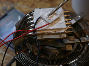
How to make a Peltier element with your own hands?
It is almost impossible to make a home-made module at home, all the more it makes no sense, given their relatively low cost (about $ 4- $ 10). But you can assemble a device that will be useful in a hike, for example, a thermoelectric generator.

To stabilize the voltage, it is necessary to assemble a simple converter on the IC chip L6920.

A voltage in the range of 0.8-5.5 V is applied to the input of such a converter; at the output it will produce stable 5 V, which is quite enough to recharge most mobile devices. If a regular Peltier element is used, it is necessary to limit the working range of the temperature of the heated side to 150 ° C. In order not to bother tracking, it is better to use a pot of boiling water as a heat source. In this case, the element is guaranteed not to heat above 100 ° C.