It's time to combine these two techniques to get a full two-way communication between Android and Arduino.
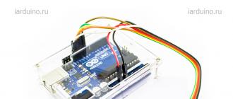
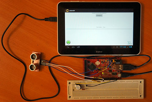
To do this, we will put together a simple project using an ultrasonic rangefinder and a piezo buzzer.
Work algorithm
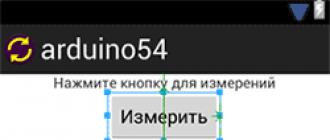
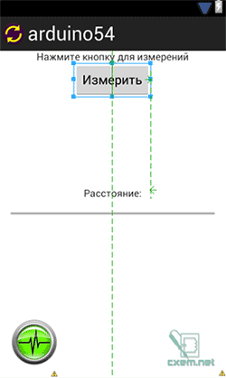
On the screen of the Android device, an activity is displayed with the "Measure" button, when pressed, the corresponding command is sent to the Arduino board. The Arduino board processes the command and starts a measurement cycle, after which the average distance to the obstacle in centimeters is calculated. This distance to the object is transmitted back to the Android device, where it is displayed as text, as well as on the slider (ProgressBar).
Data processing also takes place in Android: if the distance to the object is less than 20 cm, then a control signal is transmitted to the Arduino to turn on the buzzer. Naturally, this could be done in the Arduino code, but for clarity, I put this task on the shoulders of the Android device. In general, it turned out to be a small parktronic.
So, first you need to decide on the control commands. They must be defined in the same way on both the Arduino and the Android device. I chose the following numbers:
1 - command to enable transmission
2 - command to disable transmission
3 - command to turn on the buzzer
With the first two commands, it turned out to be a little confusing, because. I could not get Android to correctly receive one send with data (I tried to send it in a cycle and in time, but Android stubbornly refuses to accept data, I suspect that this is related to ADB and there should not be such problems when using Accessory Mode). Therefore, when the Arduino receives command 1 (transmit enable), it measures the distance and turns on the continuous transmission of data in a loop. Once Android has received the data, it sends command 2 to the Arduino to stop the transfer.
Program for Arduino
Sketch for Arduino:
#include #include // adb connection. Connection * connection; // adb connection. #define COMMAND_SEND_TRUE 1 // command to enable transmission #define COMMAND_SEND_FALSE 2 // command to disable transmission #define COMMAND_PLAY_BEEP 3 // command to turn on the buzzer const int numOfReadings = 10; // number of measurements (array elements) int readings; // measurement values in the array int arrayIndex = 0; // index of the element in the array int total = 0; // total values int averageDistance = 0; // average distance // setting up pins and variables for the ultrasonic sensor int echoPin = 2; // DYP_ME007 ECHO pin int initPin = 3; // DYP_ME007 TRIG pin int BeeperPin = 8; // buzzer pin unsigned long pulseTime = 0; // pulse duration in microseconds unsigned long distance = 0; // distance in (cm) boolean SendToAndroid = false; void setup() ( pinMode(initPin, OUTPUT); pinMode(echoPin, INPUT); pinMode(BeeperPin, OUTPUT); // Buzzer // form an array for (int thisReading = 0; thisReading< numOfReadings; thisReading++) { readings = 0; } Serial.begin(115200); // Инициализация подсистемы ADB. ADB::init(); // Open an ADB stream to the phone"s shell. Auto-reconnect. Use any unused port number eg:4568 connection = ADB::addConnection("tcp:4568", true, adbEventHandler); } void loop() { if(SendToAndroid == true) makeDimension(); ADB::poll(); // Poll the ADB subsystem. } void adbEventHandler(Connection * connection, adb_eventType event, uint16_t length, uint8_t * data) { if (event == ADB_CONNECTION_RECEIVE) // Если приняли данные { Serial.print("data:"); // Вывод в Serial Monitor для отладки Serial.println(data,DEC); if((data) == COMMAND_SEND_TRUE) SendToAndroid = true; // Флаг, что надо вкл. передачу данных else if ((data) == COMMAND_SEND_FALSE) SendToAndroid = false; //Флаг, что данные приняты и откл. передачу данных else if ((data) == COMMAND_PLAY_BEEP) playBeep(); } else if (event == ADB_CONNECTION_OPEN) Serial.println("ADB connection open"); else if (event == ADB_CONNECTION_CLOSE) Serial.println("ADB connection close"); else { Serial.println(event); } } void makeDimension() { for (int i = 0; i < numOfReadings; i++) { digitalWrite(initPin, HIGH); // посылаем импульс длительностью 10мс delayMicroseconds(10); digitalWrite(initPin, LOW); pulseTime = pulseIn(echoPin, HIGH); // Считываем длительность пришедшего импульса distance = pulseTime/58; // Дистанция = (длит. импульса / 58) см total= total - readings; readings = distance; total= total + readings; arrayIndex = arrayIndex + 1; // После того, как достигли последнего элемента, начинаем сначала if (arrayIndex >= numOfReadings) ( arrayIndex = 0; ) //Serial.println(distance, DEC); ) averageDistance = total / numOfReadings; // calculate average distance //Serial.println(averageDistance, DEC); connection->write(2,(uint8_t*)&averageDistance); // Send 2 bytes delay(10); ) void playBeep() ( for (int j = 0; j< 10; j++) { analogWrite(BeeperPin, 20); delay(50); analogWrite(BeeperPin, 0); delay(150); } }
At the very beginning, we define 3 constants - these are commands for sending messages between devices: COMMAND_SEND_TRUE = 1, COMMAND_SEND_FALSE = 2, COMMAND_PLAY_BEEP = 3
Handler adbEventHandler() is called every time when data is received and when other events occur from ADB (opening and closing a connection).
Function makeDimension() makes 10 measurements of distances, and then calculates the average value from them, which, through the command connection->write>() 2 bytes is sent to the Android device.
With function playBeep() it's simple - it is designed to play 10 short sounds through the buzzer.
Program for Android
Our activity window will consist of the following key elements:
button (Button) - to send a distance measurement command
text field (TextView) - to display the received distance
progress bar (ProgressBar) - for visual display of distance (maximum - 500 cm)
connection icon (ImageView) - displayed when an active connection with an Android device.
See the attached files for the XML file of this activity
The file for the main Activity contains the following code:
Package com.example.arduino54; import java.io.IOException; import org.microbridge.server.Server; import org.microbridge.server.AbstractServerListener; import com.example.arduino54.R; import android.os.AsyncTask; import android.os.Bundle; import android.app.Activity; import android.util.Log; import android.view.View; import android.widget.ImageView; import android.widget.ProgressBar; import android.widget.TextView; import android.widget.Button; public class MainActivity extends Activity ( private int Distance = 0; public final String APP_NAME = "arduino54"; public final byte COMMAND_SEND_TRUE = 1; // Send enable command public final byte COMMAND_SEND_FALSE = 2; // Send disable command public final byte COMMAND_PLAY_BEEP = 3; // Buzzer enable command public final int SYS_COMMAND_DATA = 0; // Internal command: data transfer public final int SYS_COMMAND_CONNECTED = 1; // Internal command: connection established public final int SYS_COMMAND_DISCONNECTED = 2; // Internal command: connection lost Server server = null; ImageView connectedImage; @Override public void onCreate(Bundle savedInstanceState) ( super.onCreate(savedInstanceState); setContentView(R.layout.activity_main); // Create TCP server (based on MicroBridge LightWeight server) try ( server = new Server(4568); //This port must also be used on the ADK board server.start(); ) catch (IOException e) ( Log.e(APP_NAME, "Unable to start TCP server", e); System.exit(-1); ) connectedImage = (ImageView) findViewById(R.id.imageConnected); connectedImage.setAlpha(20); Button Button1 = (Button)findViewById(R.id.button1); Button1.setOnClickListener(new View.OnClickListener() ( public void onClick(View v) ( try ( server.send(new byte ((byte) COMMAND_SEND_TRUE)); //Send data //Log.d(APP_NAME, "data_send: "+bSend); ) catch (IOException e) ( Log.e(APP_NAME, "Problem sending TCP message", e); ) ) )); server.addListener(new AbstractServerListener() ( @Override public void onReceive(org.microbridge.server.Client client, byte data) ( Log.d(APP_NAME, "data0:"+data+"; data1:"+data); if (data.length<2) Log.e(APP_NAME, "Размер данных менее 2-х байт:"+data.length); else { try { server.send(new byte {(byte) COMMAND_SEND_FALSE}); //Посылаем данные } catch (IOException e) { Log.e(APP_NAME, "Problem sending TCP message", e); } } Distance = ((data << 8) | (data & 0xFF)); // Формируем слово из 2-х байт //Any update to UI can not be carried out in a non UI thread like the one used //for Server. Hence runOnUIThread is used. runOnUiThread(new Runnable() { //@Override public void run() { new UpdateData().execute(Distance,SYS_COMMAND_DATA); } }); } //@Override public void onClientConnect(org.microbridge.server.Server server, org.microbridge.server.Client client){ Log.d(APP_NAME, "ClientConnected"); runOnUiThread(new Runnable() { public void run() { new UpdateData().execute(0,SYS_COMMAND_CONNECTED); } }); } public void onClientDisconnect(org.microbridge.server.Server server, org.microbridge.server.Client client){ Log.d(APP_NAME, "ClientDisconnected"); runOnUiThread(new Runnable() { public void run() { new UpdateData().execute(0,SYS_COMMAND_DISCONNECTED); } }); } }); } @Override protected void onDestroy (){ super.onDestroy(); server.stop(); } class UpdateData extends AsyncTask< Integer, Integer, Integer>( // Called to initiate the background activity @Override protected Integer doInBackground(Integer... ArdState) ( if((ArdState< 20) && (ArdState != 0)){ //Если расстояние меньше 20см try { server.send(new byte {(byte) COMMAND_PLAY_BEEP}); } catch (IOException e) { Log.e(APP_NAME, "Problem sending TCP message", e); } } return (ArdState); //Возвращаем в onPostExecute() } @Override protected void onProgressUpdate(Integer... values) { super.onProgressUpdate(values); // Not used in this case } @Override protected void onPostExecute(Integer... result) { Log.d(APP_NAME, "onPostExecute:"+result); Log.d(APP_NAME, "onPostExecute:"+result); if(result == 1){ connectedImage.setAlpha(255); } else if(result == 2){ connectedImage.setAlpha(20); } TextView txt_Distance_Arduino = (TextView) findViewById(R.id.textDistance); txt_Distance_Arduino.setText(String.valueOf(result+" см")); // Выводим на activity дистанцию ProgressBar mProgressBar = (ProgressBar)findViewById(R.id.progressBar1); mProgressBar.setProgress(result); } } }
Here we are for class server define method server.addListener(new AbstractServerListener() ()), and: onReceive(), onClientConnect() And onClientDisconnect() which is called when receiving data from the MicroBridge server, when connecting and disconnecting.
On the Button1 button, we hang the click event handler setOnClickListener(). When the button is pressed, this method is called and sends the COMMAND_SEND_TRUE command to the Arduino board, by which the Arduino measures the distance and transfers the distance value.
In method onReceive(), as soon as we have received the data, we immediately send back the COMMAND_SEND_FALSE command, so that the Arduino turns off the transmission of packets. I wrote about this algorithm above.
Note that we use the internal system commands SYS_COMMAND_DATA, SYS_COMMAND_CONNECTED and SYS_COMMAND_DISCONNECTED to pass data to a separate thread. Commands are transmitted by the 2nd element of the array, and the first element contains the measured distance received from the Arduino.
When the event fires onClientConnect(), a new thread is created to which an array is passed with the SYS_COMMAND_CONNECTED command (in our case 0), and in the method onPostExecute() by setting the Alpha value to the maximum of 255, the connection icon is displayed. Upon receipt of the SYS_COMMAND_DISCONNECTED command, Alpha is set to 20, the icon becomes faded and almost invisible, which means that the connection has not been established. Alpha transparency is set by the method setAlpha(int).
When a thread receives data from the onReceive method, then in the method doInBackground() the conditions are compared, and if the distance is not early to zero and less than 20 cm, then the method server.send() the COMMAND_PLAY_BEEP command is sent to turn on the buzzer on the Arduino board.
In method onPostExecute() UI elements are displayed to display the numerical value of the distance and the strip on the progress bar.
In the attached file you can download projects for Arduino and Android, as well as all the necessary libraries
Let's load the standard example "Physical Pixel" through the menu File\Examples\4.Communication\PhysicalPixel. This program waits for data from the computer. When an ‘H’ character is received, the test indicator lights up, when an ‘L’ character is received, it goes out. Let's analyze its source code:
int outputPin = 13 ; // here we store the contact number
int value; // received character will be stored here
void setup()
{
Serial.begin(9600) ; //set the port to 9600 bps
pinMode(outputPin, OUTPUT) ; // set pin 13 to output mode
}
void loop()
{
if(Serial.available())( //if there is an accepted character,
val = Serial.read(); // then read it and store it in val
if (val == "H" ) ( // if character "H" is accepted...
digitalWrite(outputPin, HIGH) ; // then turn on the LED
}
if (val == "L" ) ( // if character "L" is accepted,
digitalWrite(outputPin, LOW) ; // then turn off the LED
}
}
}
Notice the nested conditions and the order of the opening and closing curly braces. For the convenience of reading the program code, each next level of nesting is shifted to the right. In addition, the editor helps to read the code - if you put the cursor to the right of the bracket, it will highlight the corresponding pair of brackets.
How to check the operation of this program after you download it to the microcontroller? We need to find a way to send characters to the computer's COM port so that the microcontroller receives and processes them. There are many options for solving this problem.
We use the built-in COM port monitor in the Arduino development environment
This is the simplest and most understandable method for beginners.
The COM port monitor is launched through the Tools\Serial Monitor menu, or through the toolbar. In older versions of the software, the monitor was only available through the toolbar: . When calling the monitor, make sure that the same baud rate is selected as in the microcontroller program. Now you can enter any characters in the input field on the right, and press the "Send" button - the entered characters will be sent to the port, and your program will accept them there. Enter the Latin letter "H" there, press "Send" - the test LED will light up. If you send "L" - it will turn off. By the way, all the data that your program will send to the COM port will be displayed in the window below.
Using the terminal emulation program HyperTerminal
This is a slightly more complex exchange option to implement.
Windows usually includes a terminal emulation program called HyperTerminal. In Windows XP, it can be found under Start\All Programs\Programs\Accessories\Communications\HyperTerminal. At startup, you need to refuse to create a connection, select the menu File \ Properties. In the dialog that appears, select your COM port, click "Configure", and configure the communication settings in accordance with the figure:

You can use another terminal emulator - they all usually have similar functionality and similar settings.
Click "OK" in both windows, and once in the main program window, any key on the keyboard - HyperTerminal will connect to the COM port. Now all the characters typed on the keyboard go through the COM port to the microcontroller, and everything that the microcontroller sends goes to the screen. Press the "H" and "L" keys (watch the selected language and case) - the test LED should light up and go out.
Let's write our own PC program!
This option is for true enthusiasts who want to program not only Freeduino, but also PC. Why not? We don't need to learn the details of Windows serial programming or any other complicated stuff. Especially for solving such simple tasks, there is the Processing language (http://processing.org), which is very similar in syntax and even the development environment to the Arduino software.
Install and run Processing - You will see an Arduino-like development environment.
The source code for the Processing language is in the comments below the main text of the Physical Pixel example. Here it is with minimal changes - we fixed the port opening so that you can easily replace its number:
import processing.serial.* ;
serial port;
void setup()
{
size(200 , 200 ) ;
noStroke() ;
frameRate(10) ;
port = new Serial(this , "COM5" , 9600 ) ; // !!! Enter your COM port here!
}
boolean mouseOverRect() //Returns true if the cursor is inside a square
{
return ((mouseX >= 50 ) && (mouseX<=
150
)
&&
(mouseY >= 50 ) & (mouseY<=
150
)
)
;
}
void draw()
{
background(#222222 ) ;
if (mouseOverRect() ) // If the cursor is inside a square....
{
fill(#BBBBB0) ; // change color to brighter
port.write("H") ; // send "H" to microcontroller
) else ( // if not inside...
fill(#666660 ) ; // change color to darker
port.write("L") ; // send "L" to microcontroller
}
rect(50 , 50 , 100 , 100 ) ; // draw a square
}
Run the program (via the Sketch \ Run menu) - a window with a square will appear, when you place the mouse cursor in it, the LED on Freeduino will light up.
A description of the Processing language and its capabilities is beyond the scope of this simple narrative, but many of the Arduino examples in the comments below the body of the program show Processing PC code that interacts with Freeduino.
It is simply vital for him to exchange information with the microcontroller. There are situations when you need to manually, by controlling from a PC or laptop, activate one or another function in the microcontroller program.
But let's get down to business. It's not that difficult to exchange data with the Arduino, but the catch is that the data is transmitted character by character, which is very bad. In search of this problem, I had to spend quite a long time, until I came across one wonderful library on Habrahabr. The author implemented in it the function of accepting numbers, i.e. you can send more than one digit to the controller and it will work correctly. Download the library (link), unpack it into hardwarelibraries, and let's move on to practice.
First of all, we will write a sketch, and upload it to the Arduino (Freeduino)
#include void setup() (
Serial.begin(9600); // set port speed
PinMode(9, OUTPUT); // set pin 9 as speaker output
) void loop()
Long intNumber; Serial.print("Enter number: ");
Number = SerialInput.InputNumber(); // Enter a number Serial.print("Result = ");
Serial.println(Number * Number, DEC);
Beep(500);
} void beep(unsigned char delayms)(
analogWrite(9, 20); // value must be between 0 and 255
// experiment for good tone
analogWrite(9, 0); // 0 - turn off the piezo
Delay(delayms); // pause delayms ms
What does all of this mean. I tried to provide the code with detailed comments, everything seems to be clear. This sketch asks you to enter any number, after which it gives out its square, and plays a sound signal through a piezo speaker connected to pin 9.
And now, the most interesting thing - it's time to try. For switching with the controller, I recommend using a free program putty. In the Connection type settings, select Serial and enter the correct port number instead of COM1 (you can peek in the Arduino programming environment in the Tools->Serial Port menu). We press Open, and we see the inscription Enter number in the console, we enter any number (within reason), we press Enter, and we see the result.
Everything, you can rejoice and jump for joy. Naturally, all this can be improved, for example, first display a menu to send from the controller to the console, in which to describe the commands in detail. For example, enter the number 0 - the LED backlight turns on, press 1 - it goes out. Thus, you can shove at least 100500 commands, if only there is enough microcontroller memory (which is so small). And we'll talk about how to expand the available memory next time.
UPD: part of the code was cut by the engine parser, so here is the source
A COM port is most often used to connect the microcontroller to a computer. In this article, we will show how to send control commands from a computer and send data from a controller.
Preparation for work
Most microcontrollers have multiple I/O ports. The UART protocol is the most suitable for communication with a PC. It is a serial asynchronous data transfer protocol. To convert it to a USB interface, the board has a USB-RS232 converter - FT232RL.
You only need an Arduino-compatible board to run the examples in this article. We use . Make sure your board has an LED connected to pin 13 and a reset button.
For example, let's upload a code to the board that displays an ASCII table. ASCII is an encoding for representing decimal digits, the Latin and national alphabets, punctuation marks, and control characters.
int symbol = 33 ; void setup() ( Serial. begin(9600 ) ; Serial. println(" ASCII Table ~ Character Map " ) ; ) void loop() ( Serial. write(symbol) ; Serial. print(" , dec: " ) ; Serial .print(symbol) ; Serial.print(" , hex: " ) ; Serial.print(symbol, HEX) ; Serial.print(" , oct: " ) ; Serial.print(symbol, OCT) ; Serial.print( " , bin: " ) ; Serial.println(symbol, BIN) ; if (symbol == 126 ) ( while (true) ( continue ; ) ) symbol+ + ; )The symbol variable stores the symbol code. The table starts at 33 and ends at 126, so symbol is initially set to 33.
To start the operation of the UART port, use the function Serial.begin(). Its only parameter is speed. The speed must be negotiated on the transmitting and receiving sides in advance, since the transmission protocol is asynchronous. In this example, the speed is 9600bps.
Three functions are used to write a value to a port:
- Serial.write()– writes data to the port in binary form.
- Serial.print() can have many values, but all of them serve to display information in a human-friendly form. For example, if the information specified as a parameter to pass is enclosed in quotes, the terminal program will display it unchanged. If you want to display any value in a certain number system, then you need to add a service word: BIN-binary, OCT - octal, DEC - decimal, HEX - hexadecimal. For example, Serial.print(25,HEX).
- Serial.println() does the same as Serial.print(), but still translates the string after displaying the information.
To check the operation of the program, it is necessary that the computer has a terminal program that receives data from the COM port. The Arduino IDE already has one built in. To call it, select Tools->Port Monitor from the menu. The window of this utility is very simple:
Now click the restart button. The MK will reboot and display the ASCII table:
Pay attention to this part of the code:
if (symbol = = 126 ) ( while (true) ( continue ; ) )It stops the execution of the program. If you exclude it, the table will be displayed indefinitely.
To consolidate the acquired knowledge, try writing an infinite loop that will send your name to the serial port once a second. Add step numbers to the output and don't forget to translate the line after the name.
Sending commands from PC
Before doing this, you need to get an idea of how a COM port works.
First of all, all exchange occurs through the memory buffer. That is, when you send something from a PC to a device, the data is placed in some special section of memory. As soon as the device is ready, it reads the data from the buffer. The function allows you to check the state of the buffer serial.avaliable(). This function returns the number of bytes in the buffer. To subtract these bytes, you need to use the function Serial.read(). Let's see how these functions work with an example:
After the code is loaded into the microcontroller's memory, open the COM port monitor. Type one character and press Enter. In the received data field you will see: “I received:X”, where instead of X will be the character you entered.
The program spins indefinitely in the main loop. At the moment when a byte is written to the port, the Serial.available() function takes the value 1, that is, the condition is fulfilled Serial.available() > 0. Next function Serial.read() reads this byte, thereby clearing the buffer. After that, using the functions already known to you, the output occurs.
Using the Arduino IDE's built-in COM port monitor has some limitations. When sending data from the board to the COM port, the output can be organized in an arbitrary format. And when sending from the PC to the board, the transfer of characters occurs in accordance with the ASCII table. This means that when you enter, for example, the character “1”, the binary “00110001” (that is, “49” in decimal) is sent through the COM port.
Let's change the code a little and check this statement:
After downloading, in the port monitor when sending “1”, you will see in response: “I received: 110001”. You can change the output format and see what the board accepts with other characters.
Device control via COM port
Obviously, by commands from a PC, you can control any functions of the microcontroller. Download the program that controls the operation of the LED:
int val = 0 ; void setup() ( Serial. begin(9600 ) ; ) void loop() ( if (Serial. available() > 0 ) ( val = Serial. read() ; if (val= = "H" ) digitalWrite(13 , HIGH) ; if (val= = "L" ) digitalWrite(13 , LOW) ; ) )When the “H” character is sent to the COM port, the LED on the 13th output lights up, and when “L” is sent, the LED will go out.
If, based on the results of receiving data from the COM port, you want the program to perform different actions in the main loop, you can check the conditions in the main loop. For example.
Foreword
The development of technology has made it possible to fit several system devices on one small board, the device is called a microcontroller. One such single-crystal microcomputer is the Arduino, which consists of a microcontroller mounted on a printed circuit board and the minimum required components for operation. To create a new electronic device, you will need an Arduino board, a communication cable, and a computer. For software in the form of a control program, basic knowledge of the C / C ++ language variant for microcontrollers, since components have been added that allow writing programs without knowledge of the hardware.
Communication via bluetooth
In fact, the Bluetooth module is a modem, since it converts the signal from one medium to another. The serial TTL signal transmitted by electrical impulses through conductors is converted into a radio signal in a Bluetooth transceiver and vice versa, it is converted from a radio signal into an electrical impulse signal. The function of a modem is to establish a connection with other modems to exchange information and disconnect the communication channel. To perform connection functions, modems have two operating modes:
command - information exchange in this mode occurs with the modem itself;
data mode - information is exchanged through the modem itself.
Bluetooth modems are similar in their principle of operation to any other types of modems and they contain a set of Hayes AT protocol commands, similar to telephone modems. The commands of this protocol are written in ASCII characters. Modems on the Hayes AT protocol operate in data and command mode, mode switching is carried out by the +++ line.
Microcontrollers and application control
Microcontroller - a microcircuit with several contacts "input" and "output". Control via a microcircuit is carried out according to the simplest principle and has three main stages:
1) various sensors are connected to the inputs that detect movement, sound, lighting level, etc.
2) Control devices are connected to the outputs, such as lighting systems, speakers, motors, etc.
3) a program for controlling the microcontroller and the application is written.
Control program:
#include
#include
const
intchipSelect= 4
;
void
setup()
/* Open serial communications and wait for port to open: */
Serial.begin( 9600 );
while(!Serial)() /* wait for serial port to connect. Needed for Leonardo only */
Serial.print("Initializing SD card..." );
/* see if the card is present and can be initialized: */
if(!SD.begin(chipSelect)) (
Serial.println( “Card failed or not present”);
// don't do anything more:
return;
}
Serial. println("card initialized.");
}
void
loop()
// make a string for assembling the data to log:
String dataString = "" ;
// read three sensors and append to the string:
for (intanalogPin = 0 ; analogPin< 3 ; analogPin++) (
intsensor = analogRead(analogPin);
DataString += String(sensor);
if(analogPin< 2
) {
DataString += “,”
;
}
}
Arduino
Arduino is an open platform consisting of a microcontroller board and software (software) - IDE (Integrated Development Environment). The software for the board is written in applications on a computer and is downloaded to the device through the connection channel with the board.
The basis of the Arduino program consists of two commands: setup() and loop(). Variables are written before the setup() command, libraries are involved. The setup() command is executed only once after each connection or reset of the board controlled by the Arduino. This command starts the variables and operation of the input and output ports of the board. This command is mandatory for the control program. The loop() command is intended for cyclic execution of commands that are written in its body. An example of the implementation of these commands in the program:
setup()
{
Serial.begin( 9600
);
}
loop()
{
Serial println(millis());
Delay( 1000
);
}
.
A set of codes grouped into a block and having a name written on this code is called a function. The code set is executed when the function is called. To reduce errors in the program and execute repetitive commands, various functions are written. When writing a function, its purpose is indicated at the beginning. For example, the value returned by a function is an integer (int). Functions that do not return a value have a type - empty (void). Behind the function is written its name and in brackets the parameters passed by the function. Eg:
type functionName(parameters)
{
statements;
}
The integral type is the delay or pause function delay(Val).
Parentheses () are placed at the beginning and at the end of functions. Eg:
type function()
{
statements;
}
The number of opening brackets must be equal to the number of closing ones, otherwise there will be critical errors in the program. Arduino has a handy parenthesis matching feature. The check is carried out in two ways: when any one bracket is selected, the paired bracket is highlighted, highlighting the point behind the bracket also highlights the pair of brackets.
The data exchange of the microcontroller with the computer occurs through a wired interface or by radio signal, the exchange of information is carried out through the library. The Arduino has standard libraries installed, but sometimes their functions are not designed to work with the equipment controlled through the microcontroller. Additional libraries are installed as needed. Standard libraries are installed in the “Libraries” folder, additional libraries are installed in the libraries folder.
Arduino and iOS app
In order to integrate Arduino with Apple (iPad or iPhone), you will need the Arduino Code application and the Blynk development environment. Arduino Code is installed on the iPad or iPhone through this application, the integration of iOS and Arduino devices is carried out. Blynk will be used to write the control program for the Arduino board. In addition to the cloud environment for work, Blynk has the ability to download applications to your computer. Since Blynk has versions for iOS in addition to Android for development, this application was chosen for integration with Apple. It is also important that Blynk can communicate with devices via Bluetooth.
At the first stage, we connect the programming board with the smartphone via the supported interfaces: SeeedStudio Ethernet Shield V2.0 (W5200), Official Ethernet Shield (W5100), RN-XV WiFly, ESP8266, Official Arduino WiFi Shield, ESP8266 (WiFi modem), Adafruit CC3000 WiFi, ENC28J60 and USB (Serial). Arduino integration with Macintosh (Apple) computers is carried out through the Tools menu. Next, the Serial Port line is selected in the menu, then the connection is made through the port whose name begins with /dev/cu.usbserial. At the second stage, we add widgets (programs) in the application, set the output addresses and, if necessary, write the code. Drag'n "drop is used to develop the widget. Blynk creates programs for Arduino boards: Due, Mini, Uno and other Arduino boards. The Arduino Code program is installed on a computer and code complete is required to write commands. The application can be downloaded from App Store.When uploading a program to the Arduino board, you must disable the Bluetooth module, since communication with the microcontroller is carried out through the same port.A 9-volt power supply will be used as a power source for the microcontroller.Also, in the Arduino Manager application, it is possible to set Ready-made widget.To control the device of the lock, the Rotary Switch widget is suitable.This widget is essentially a rotary switch (as the name suggests.It has two off / on positions.A simple and convenient widget to control the device, which only has two modes of closed / open .
We create an electronic lock from the “smart home” series
The HM-10 Bluetooth board will be used to connect the Arduino board. This module operates in Master and Slave modes. Compatible with older Arduino versions such as: HC-05;-06;-07. In order for Apple devices to detect the Bluetooth signal from the board, you need to install the program - LightBlue.
We connect a drive to the board controlled by Arduino, which will control the bolt of the lock or an electromagnetic valve, which will perform the function of locking the door. In this case, the control program will not be cumbersome and look like this:
#include
Servo myservo;
intpos = 0
;
void
setup() {
myservo.attach( 10
); /* Assign 10 pins to drive control */
}
void
loop() {
for(pos= 0
; pos< 90
; pos += 1
)/* move from 0° to 90° */
{
myservo.write(pos);
Delay( 25
); /* Specify the time with a delay (25 ms) to move to another position */
for(pos= 90
; pos > 0
; pos -= 1
) /* Move from 90° to 0° */
{
myservo.write(pos);
Delay( 25
); /* 25ms delay to reach reverse position */
}
}
Communication will be through the Arduino Manager app, which directly controls the controller via the iOS operating system. If necessary, change the connection speed setting of the Bluetooth HM-10 board.
// Connect HM10
// Pin 7/TXD
// Pin 8/RXD
#if defined(ARDUINO_AVR_UNO)
#include
SoftwareSerial mySerial(7 , 8 ); // TX, RX
#endif
#if defined(ARDUINO_AVR_MEGA2560)
#define mySerial Serial3
#endif
#define DEVICE_SPEED 9600
#define CONSOLE_SPEED 9600
void
setup() {
Serial.begin(CONSOLE_SPEED);
PinMode( 7
,OUTPUT);
PinMode( 8
, INPUT);
MySerial.begin(DEVICE_SPEED);
Serial.println("Ready");
}
void
loop() {
charc;
if(Serial.available()) (
C = Serial.read();
MySerial.print(c);
if(mySerial.available()) (
C = mySerial.read();
Serial print(c);
}
}
conclusions
To create such a locking mechanism, of course, you will need an Arduino board, servos, and writing a control program and other components, depending on the task. The device will be controlled on an iPad or iPhone via Bluetooth via the Arduino Manager app. This application is downloaded from the App Store and is designed to manage multiple devices. It has an easy control setting and a feedback sensor. The code generator allows you to create a communication infrastructure between an Arduino board and an iOS device and generate code for each selected device. It is also possible to use a ready-made widget to control the device.
Arduino makes it possible to experiment and apply this microcontroller to various devices. The Arduino Manager app controls these devices from your iPad or iPhone.
Bibliographic list
- Projects using the Arduino controller. Petin V. A. St. Petersburg "BHV-Petersburg" 2014. Pp. 18-19. Page 47.
- Arduino, sensors and networks for device communication. Per. from English. - 2nd ed. - St. Petersburg: BHV-Petersburg, 2015. Pp. 102.
- Arduino programmer's notebook. Brian W Evans Published: First Edition Auqust 2007 Page 9-10.
- Blynk is a cloud-based widget development environment for iOS and Android. Network access resource: