Connection to Arduino:
First you need to install the RFID Library for MFRC522.
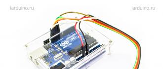
Contacts on the module The RC522 RFID module must be connected to the Arduino. For connection it is convenient to use wires father-mother.

Description of contacts on RFID module RC522:
- VCC - Power. Need 3.3V;
- RST - reset. Reset line. Never connect to the RESET pin on the CraftDuino! This pin clings to a digital port with PWM;
- GND - Ground. Earth
- MISO - Master Input Slave Output - data from slave to master, SPI;
- MOSI - Master Output Slave Input - data from master to slave, SPI;
- SCK - Serial Clock - clock signal, SPI;
- NSS - Slave Select - slave selection, SPI;
- IRQ - interrupt line;
| MFRC522 | Arduino Uno | Arduino Mega | Arduino Nano v3 | Arduino Leonardo/Micro | Arduino Pro Micro |
| RST | 9 | 5 | D9 | RESET/ICSP-5 | RST |
| SDA(SS) | 10 | 53 | D10 | 10 | 10 |
| MOSI | 11 (ICSP-4) | 51 | D11 | ICSP-4 | 16 |
| MISO | 12 (ICSP-1) | 50 | D12 | ICSP-1 | 14 |
| SCK | 13 (ICSP-3) | 52 | D13 | ICSP-3 | 15 |
| 3.3V | 3.3V | 3.3V | Stabilizer 3.3V | Stabilizer 3.3V | Stabilizer 3.3V |
| GND | GND | GND | GND | GND | GND |
The RFID-RC522 module comes with two tags, one in the form of a plastic card, and the second in the form of a key fob. If necessary, they can be purchased separately.
After everything is connected, the indicator on the module will be on, this indicates that power is supplied to the RFID . It's time run a test sketch which is in the library we have installed.

It is necessary to check the correctness of the specified constants:
#define SS_PIN 10 #define RST_PIN 9 // These constants match
Now upload the sketch to arduino and turn it on Serial port monitoring.
We bring the label to the reader and the module reads all the data from this label, for example, the unique identifier of the label UID.

RFID-RC522 operation video:
RFID tags have become an integral part of our lives; modern automation systems and smart devices are inconceivable without them. Arduino provides us with excellent opportunities to use modern technologies even in initial projects. In this article, we will explain what RFID is, review the standards, types of cards, learn how to connect popular RFID readers RC522 and RDM3600 to Arduino.
RFID (Radio Frequency Identification) is a method of transmitting, recording and storing data using radio signals. Each RFID system includes a reader/reader and an RFID tag that stores data. The tags consist of two parts - an integrated circuit and an antenna. An integrated circuit allows you to store and process data, an antenna - to receive and transmit information.
All RFID systems can be divided by range:
- Near identification - distance no more than 20 cm;
- Medium identification - distance from 20 cm to 5 m;
- Long-range identification - maximum 300 m.
In terms of frequencies, we can distinguish:
- Systems operating in the low frequency range (125 kHz, 134 kHz);
- Operating in the mid-frequency range (13.56 MHz);
- Operating in the high frequency range (800 MHz - 2.4 GHz).
The most popular band is the midrange - it is widely used in transportation applications and other projects where card overwriting is required. The main standards are ISO 14443, ISO 15693 and EPC. Smart cards are produced based on the ISO 14443 standard. ISO 15693 is used to rewrite labels. EPC is an analogue of barcodes, it has a simpler and more understandable structure.
The HF band has recently come into use, mainly for warehouse applications. This range uses ISO 18000 and EPC standards. The ISO 18000 standards are of most interest and are used in applications with extended range tags. For ISO 18000, there are also several standards that differ in frequency:
- ISO 18000-1 (determination of those parameters that need to be standardized);
- ISO 18000-2 (for parameters with contactless communication interface less than 135 kHz);
- ISO 18000-3 (for contactless interface at 13.56 MHz);
- ISO 18000-4 (for 2.45 GHz);
- ISO 18000-6 (for frequency 860-930MHz);
- ISO 18000-7 (for 433 MHz).
Benefits of RFID
- No line of sight required;
- Almost 100% signal identification;
- Possibility of application in hostile environment;
- Long service life;
- RFID tag is hard to fake;
- Ability to store and transfer large amounts of information.
Application areas of RFID identification
RFID technology is often used in retail, libraries and archives, logistics, access control systems (ACS), people provisioning, product authentication.
For personnel identification, the most popular formats are plastic contactless cards and contactless key fobs. With their help, you can register the entrance / exit of objects on the territory through the points of passage - gates, checkpoints. The main task of the ACS is access control - for example, restricting access to any territory, identifying persons who may enter the territory. Additional tasks can also be solved - control of working hours for staff, maintaining a database of visitors, working with security systems, payroll.
RFID key fobs are also used for access intercoms. To open doors, Proximity key fobs are most often used, that is, short-range key fobs operating at a distance of 10-15 cm. Proximity is also divided into several formats - the most popular today are EM-Marin, HID for contactless keys and MIFARE, which include contactless smart cards.
Brief description of Arduino modules
Arduino RFID RC522 Module
The RC522 RFID module is based on the MFRC522 circuit, which provides wireless communication at a frequency of 13.56 MHz. You can connect the microcircuit via the SPI, I2c and UART interface. NFC Reader protocol standard ISO 14443.
Specifications of RFID RC522 module:
- Supply voltage 3.3 V;
- Maximum current consumption 30 mA;
- Frequency band 13.55-13.57 MHz;
- Reading distance up to 25 mm;
- Operating temperature from -20C to 80C.
The pinout of the module is shown in the figure. The SDA pin (SS, CS, NSS) is responsible for selecting the slave. The SCK output is the SPI clock signal. MOSI is responsible for transferring data from master to slave, MISO is responsible for transferring data from slave to master. IRQ - Performs an interrupt. RST - Performs an interrupt.
RDM6300 is a proximity reader that is used to remotely read the RFID key fob number and transmit the number via UART to the microcontroller that controls the lock in access systems. The device has several advantages - low price and ease of installation. It is most often used in access control systems for houses, garages, offices, apartments and other buildings with an electromechanical lock. The reader is used to read EM4100/TK4100 cards. The RDM6300 can be wall or cabinet mounted. Arduino is usually used as a microcontroller.
RDM6300 Specifications:
- Maximum current consumption 50 mA;
- Supply voltage 5 V;
- Operating frequency 125 kHz;
- Operating temperatures from -10C to 70C.
The pinout is shown in the figure.
Pin TX is responsible for transmitting data, RX - for receiving. 3 output is not used.
For P2, the ANT1 and ANT2 outputs are used to connect the antenna.
Connecting RC522 to Arduino
To connect, you will need an Arduino board, an RC522 reader, a computer, wires and a wireless RFID tag.
The RC522 module is connected to the arduino according to the following scheme:
The supply voltage is provided from 2.5 to 3.3 V. The RST output is connected to the D9 pin on the arduino, SDA to D10, MOSI to D11, MISO to D12, SCK to D13. In this case, the Arduino Nano v3 and Arduino Uno boards are considered. Once everything is connected, the LED on the RC522 will light up.
In this lesson, we will learn how to make a simple system that will unlock the lock using an electronic key (Label).
In the future, you can refine and expand the functionality. For example, add the function "adding new keys and removing them from memory". In the basic case, consider a simple example, when a unique key identifier is pre-specified in the program code.
In this tutorial we will need:
To implement the project, we need to install the libraries:
2) Now you need to connect the Buzzer, which will give a signal if the key worked and the lock opens, and the second signal when the lock closes.
We connect the buzzer in the following sequence:
| Arduino | Buzzer |
|---|---|
| 5V | VCC |
| GND | GND |
| pin 5 | IO |
3) A servo will be used as the unlocking mechanism. Any servo can be chosen, depending on the dimensions you require and the forces that the servo creates. The servo has 3 pins:
More clearly, you can see how we connected all the modules in the picture below:

Now, if everything is connected, then you can proceed to programming.
Sketch:
#include
Let's analyze the sketch in more detail:
In order to find out the UID of the card (Labels), you need to write this sketch to arduino, assemble the circuit described above, and open the Console (Monitoring of the serial port). When you bring the tag to the RFID, a number will be displayed in the console

The resulting UID must be entered in the following line:
If (uidDec == 3763966293) // Compare the Uid of the label, if it is equal to the specified one, then the servo opens the valve.
For each card, this identifier is unique and does not repeat. Thus, when you present a card whose ID you have set in the program, the system will open access using a servo.
Video:
Nowadays, the use of radio frequency identification (RFID) technology is becoming very popular. Many applications are being introduced into various areas of our lives and used for various purposes. RFID enables wireless data collection using electronic tag readers attached to or embedded in objects for identification and other purposes. This article shows how to build a simple, homemade RFID access control device using an Arduino UNO and an RFID reader (EM-18) to control an LED and a relay. The circuit diagram and the Arduino sketch (source code) are shown below.
When enabled, the reader transmits an RF signal. When an RFID tag is placed near a reader, it receives an RF signal through an antenna inside the tag. The received RF signal will be converted into electrical energy, which is sufficient to transmit data from the tag back to the RFID reader. In addition, the reader will transmit the tag ID to an external device via the serial data port. A wide range of reader models are currently available. The most common and convenient to use is the EM-18 module. This module reads RFID passive tags and sends the tag ID to the Arduino microcontroller.
ReadingRFID tag ID
To get started, download the simple code rfid1.ino on the Arduino Uno using the IDE development tool.
Now assemble the circuit as shown below.

Open the Serial Monitor in the Arduino IDE, hold the RFID tag very close to the center of the RFID reader, and note the displayed tag ID. This unique identifier will be needed in the next sketch! (Our tag has ID 51005F46642C)
Access control
At this point, the system is configured to compare the unique identifier (label in use) with the identifier of any label to be read.
Parse the existing connection and upload a new sketch rfid2.ino to Arduino microcontroller


Re-wire the hardware components (with some modifications) as shown in the figure above. Here, the D12 pin of the Arduino microcontroller is used to drive a standard 5mm LED. Pin D13 is used to control the electromagnetic relay through the control transistor. Each time a mark is matched, a high control signal appears at pin D13 for 5 seconds. The relay can be used to control an external load such as a door stop. If the label values do not match, then D13 remains low, but D12 remains high to trigger the alarm LED.
Today I will talk about the RC522 RFID module, based on the MFRC522 chip. Power supply 3.3V, detection range up to 6cm. Designed for reading and writing RFID tags with a frequency of 13.56 MHz. The frequency in this case is very important, since RFID tags exist in three frequency ranges:
- LF band marks (125-134 kHz)
- HF band tags (13.56 MHz)
- UHF band tags (860-960 MHz)
Specifically, this module works with HF range tags, in particular with the MIFARE protocol.
To work with the module, you can use the standard RFID library included in the Arduino IDE, but there is another library written specifically for this module - MFRC522 (1 Mb). Both libraries are quite convenient, but MFRC522 has more special functions that allow you to minimize the resulting program code.
Connection
Some will run into a problem - the name of the pins in most tutorials and tutorials may not match the pinout on your module. If the SS pin is indicated in the sketches, but your module does not have it, then most likely it is marked as SDA. Below I will give a module connection table for the most common boards.
| MFRC522 | Arduino Uno | Arduino Mega | Arduino Nano v3 | Arduino Leonardo/Micro |
Arduino Pro Micro |
| RST | 9 | 5 | D9 | RESET/ICSP-5 | RST |
| SDA(SS) | 10 | 53 | D10 | 10 | 10 |
| MOSI | 11 (ICSP-4) | 51 | D11 | ICSP-4 | 16 |
| MISO | 12 (ICSP-1) | 50 | D12 | ICSP-1 | 14 |
| SCK | 13 (ICSP-3) | 52 | D13 | ICSP-3 | 15 |
| 3.3V | 3.3V | 3.3V | Stabilizer 3.3V | Stabilizer 3.3V | Stabilizer 3.3V |
| GND | GND | GND | GND | GND | GND |
The control pins SS(SDA) and RST are specified in the sketch, so if your board is different from the one I will use in my examples, and I use UNO R3, specify the pins from the table at the beginning of the sketch:
#define SS_PIN 10 #define RST_PIN 9
Example #1: Reading the card number
Consider an example from the RFID library - cardRead. It does not give out data from the card, but only its number, which is usually enough for many tasks.
#include #include #define SS_PIN 10 #define RST_PIN 9 RFID rfid(SS_PIN, RST_PIN); // Data about the card number is stored in 5 variables, we will remember them to check if we have already read such a card int serNum0; int serNum1; intserNum2; int serNum3; int serNum4; void setup() ( Serial.begin(9600); SPI.begin(); rfid.init(); ) void loop() ( if (rfid.isCard()) ( if (rfid.readCardSerial()) ( // Compare the card number with the previous card number if (rfid.serNum != serNum0 && rfid.serNum != serNum1 && rfid.serNum != serNum2 && rfid.serNum != serNum3 && rfid.serNum != serNum4) ( /* If the card is - new, then read*/ Serial.println(" "); Serial.println("Card found"); serNum0 = rfid.serNum; serNum1 = rfid.serNum; serNum2 = rfid.serNum; serNum3 = rfid.serNum; serNum4 = rfid.serNum; //Print the card number Serial.println("Cardnumber:"); Serial.print("Dec: "); Serial.print(rfid.serNum,DEC); Serial.print(", "); Serial .print(rfid.serNum,DEC); Serial.print(", "); Serial.print(rfid.serNum,DEC); Serial.print(", "); Serial.print(rfid.serNum,DEC); Serial.print(", "); Serial.print(rfid.serNum,DEC); Serial.println(" "); Serial.print("Hex: "); Serial.print(rfid.serNum,HEX); Serial .print(", "); Serial.print(rfid.serNum,HEX); Serial.print(", "); Serial.print(rfid.serNum,HEX); Serial.print(", "); Serial.print(rfid.serNum,HEX); Serial.print(", "); Serial.print(rfid.serNum,HEX); Serial.println(" "); ) else ( /* If it's already a read card, just print the dot */ Serial.print("."); ) ) ) rfid.halt(); )
The sketch uploaded, the power LED on the module turned on, but the module does not respond to the card? Do not panic, or run to look for the "correct" examples of work. Most likely, there is simply no contact on one of the pins - the holes on the board are slightly larger than the thickness of the jumper, so it's worth trying to rearrange them. Is the LED on the board not on? Try changing the jumper that leads to 3.3V and make sure that it is connected to 3.3V on the board, supplying power to 5V can easily kill your board.
Let's say everything worked for you. Then, reading the tags by the RFID module, we will see the following in the serial port monitor:
Here I read 3 different marks, and as you can see, he successfully read all 3.
Example #2: Reading data from a card
Let's consider a more developed option - it will read not only the card number, but also all the data available for reading. This time we will take an example from the MFRC522 library - DumpInfo.
#include #include #define RST_PIN 9 // #define SS_PIN 10 // MFRC522 mfrc522(SS_PIN, RST_PIN); // Create MFRC522 instance void setup() ( Serial.begin(9600); // Initialize serial port monitor while (!Serial); // Do nothing until it is open (for Arduino on ATMEGA32U4 chip) SPI.begin() ; // Initialize the SPI bus mfrc522.PCD_Init(); // Initialize the RFID module ShowReaderDetails(); // Display data about the MFRC522 module Serial.println(F("Scan PICC to see UID, type, and data blocks..." )); ) void loop() ( // Looking for a new card if (! mfrc522.PICC_IsNewCardPresent()) ( return; ) // Selecting one of the cards if (! mfrc522.PICC_ReadCardSerial()) ( return; ) // Displaying data from the card mfrc522.PICC_DumpToSerial(&(mfrc522.uid)); ) void ShowReaderDetails() ( // Get module version number byte v = mfrc522.PCD_ReadRegister(mfrc522.VersionReg); Serial.print(F("MFRC522 Software Version: 0x ")); Serial.print(v, HEX); if (v == 0x91) Serial.print(F(" = v1.0")); else if (v == 0x92) Serial.print(F(" = v2.0")); else Serial.print(F(" (unknown)")); Serial.println(""); // When we get 0x00 or 0xFF, communication failed if ((v == 0x00) || (v == 0xFF)) ( Serial. println(F("WARNING: Communication failure, is the MFRC522 properly connected?")) ; ) )
If the previous example worked without errors, then this should not be a problem either. Although, the metro ticket, which issued the card number without any problems in the previous example, turned out to be with an undefined data type in this one, and the module could not read anything other than the card number.
As a result, after reading the data from the card, we get its type, identifier, and data from 16 memory sectors. It should be noted that MIFARE 1K cards consist of 16 sectors, each sector consists of 4 blocks, and each block contains 16 bytes of data.
Example #3: Writing a new ID to the card
In this example, we will consider changing the card identifier (UID). It is important to know that not all cards support ID change. The card may be writable, but that only means that the data is writable. Unfortunately, the cards that I had in my hands did not support UID rewriting, but I will give the sketch code here just in case.
#include #include /* Set new UID here */ #define NEW_UID (0xDE, 0xAD, 0xBE, 0xEF) #define SS_PIN 10 #define RST_PIN 9 MFRC522 mfrc522(SS_PIN, RST_PIN); MFRC522::MIFARE_Key; void setup() ( Serial.begin(9600); while (!Serial); SPI.begin(); mfrc522.PCD_Init(); Serial.println(F("Warning: this example overwrites the UID of your UID changeable card, use with care!")); for (byte i = 0; i< 6; i++) { key.keyByte[i] = 0xFF; } } void loop() { if (! mfrc522.PICC_IsNewCardPresent() || ! mfrc522.PICC_ReadCardSerial()) { delay(50); return; } // Считываем текущий UID Serial.print(F("Card UID:")); for (byte i = 0; i < mfrc522.uid.size; i++) { Serial.print(mfrc522.uid.uidByte[i] < 0x10 ? " 0" : " "); Serial.print(mfrc522.uid.uidByte[i], HEX); } Serial.println(); // Записываем новый UID byte newUid = NEW_UID; if (mfrc522.MIFARE_SetUid(newUid, (byte)4, true)) { Serial.println(F("Wrote new UID to card.")); } // Halt PICC and re-select it so DumpToSerial doesn"t get confused mfrc522.PICC_HaltA(); if (! mfrc522.PICC_IsNewCardPresent() || ! mfrc522.PICC_ReadCardSerial()) { return; } // Считываем данные с карты Serial.println(F("New UID and contents:")); mfrc522.PICC_DumpToSerial(&(mfrc522.uid)); delay(2000); }
Example #4: Writing Data to a Card
And finally, what we have been getting to for so long - writing data to the card. The sweetest part of working with the module is the ability to make a copy of an existing map, add something or change something, it's much more interesting than just reading it.
Let's change one of the data blocks on the map:
#include #include #define RST_PIN 9 #define SS_PIN 10 MFRC522 mfrc522(SS_PIN, RST_PIN); MFRC522::MIFARE_Key; void setup() ( Serial.begin(9600); while (!Serial); SPI.begin(); mfrc522.PCD_Init(); // Prepare the key // use the key FFFFFFFFFFFFh which is the standard for empty cards for (byte i = 0 i< 6; i++) { key.keyByte[i] = 0xFF; } Serial.println(F("Scan a MIFARE Classic PICC to demonstrate read and write.")); Serial.print(F("Using key (for A and B):")); dump_byte_array(key.keyByte, MFRC522::MF_KEY_SIZE); Serial.println(); Serial.println(F("BEWARE: Data will be written to the PICC, in sector #1")); } void loop() { // Ждем новую карту if (! mfrc522.PICC_IsNewCardPresent()) return; // Выбираем одну из карт if (! mfrc522.PICC_ReadCardSerial()) return; // Показываем подробности карты Serial.print(F("Card UID:")); dump_byte_array(mfrc522.uid.uidByte, mfrc522.uid.size); Serial.println(); Serial.print(F("PICC type: ")); byte piccType = mfrc522.PICC_GetType(mfrc522.uid.sak); Serial.println(mfrc522.PICC_GetTypeName(piccType)); // Проверяем совместимость if (piccType != MFRC522::PICC_TYPE_MIFARE_MINI && piccType != MFRC522::PICC_TYPE_MIFARE_1K && piccType != MFRC522::PICC_TYPE_MIFARE_4K) { Serial.println(F("This sample only works with MIFARE Classic cards.")); return; } // В этом примере мы используем первый сектор данных карты, блок 4 byte sector = 1; byte blockAddr = 4; byte dataBlock = { // Данные, которые мы запишем на карту 0x01, 0x02, 0x03, 0x04, // 1, 2, 3, 4, 0x05, 0x06, 0x07, 0x08, // 5, 6, 7, 8, 0x08, 0x09, 0xff, 0x0b, // 9, 10, 255, 12, 0x0c, 0x0d, 0x0e, 0x0f // 13, 14, 15, 16 }; byte trailerBlock = 7; byte status; byte buffer; byte size = sizeof(buffer); // Аутентификация Serial.println(F("Authenticating using key A...")); status = mfrc522.PCD_Authenticate(MFRC522::PICC_CMD_MF_AUTH_KEY_A, trailerBlock, &key, &(mfrc522.uid)); if (status != MFRC522::STATUS_OK) { Serial.print(F("PCD_Authenticate() failed: ")); Serial.println(mfrc522.GetStatusCodeName(status)); return; } // Показываем текущие данные сектора Serial.println(F("Current data in sector:")); mfrc522.PICC_DumpMifareClassicSectorToSerial(&(mfrc522.uid), &key, sector); Serial.println(); // Читаем данные из блока Serial.print(F("Reading data from block ")); Serial.print(blockAddr); Serial.println(F(" ...")); status = mfrc522.MIFARE_Read(blockAddr, buffer, &size); if (status != MFRC522::STATUS_OK) { Serial.print(F("MIFARE_Read() failed: ")); Serial.println(mfrc522.GetStatusCodeName(status)); } Serial.print(F("Data in block ")); Serial.print(blockAddr); Serial.println(F(":")); dump_byte_array(buffer, 16); Serial.println(); Serial.println(); // Аутентификация Serial.println(F("Authenticating again using key B...")); status = mfrc522.PCD_Authenticate(MFRC522::PICC_CMD_MF_AUTH_KEY_B, trailerBlock, &key, &(mfrc522.uid)); if (status != MFRC522::STATUS_OK) { Serial.print(F("PCD_Authenticate() failed: ")); Serial.println(mfrc522.GetStatusCodeName(status)); return; } // Записываем данные в блок Serial.print(F("Writing data into block ")); Serial.print(blockAddr); Serial.println(F(" ...")); dump_byte_array(dataBlock, 16); Serial.println(); status = mfrc522.MIFARE_Write(blockAddr, dataBlock, 16); if (status != MFRC522::STATUS_OK) { Serial.print(F("MIFARE_Write() failed: ")); Serial.println(mfrc522.GetStatusCodeName(status)); } Serial.println(); // Читаем данные снова, чтобы проверить, что запись прошла успешно Serial.print(F("Reading data from block ")); Serial.print(blockAddr); Serial.println(F(" ...")); status = mfrc522.MIFARE_Read(blockAddr, buffer, &size); if (status != MFRC522::STATUS_OK) { Serial.print(F("MIFARE_Read() failed: ")); Serial.println(mfrc522.GetStatusCodeName(status)); } Serial.print(F("Data in block ")); Serial.print(blockAddr); Serial.println(F(":")); dump_byte_array(buffer, 16); Serial.println(); Serial.println(F("Checking result...")); byte count = 0; for (byte i = 0; i < 16; i++) { if (buffer[i] == dataBlock[i]) count++; } Serial.print(F("Number of bytes that match = ")); Serial.println(count); if (count == 16) { Serial.println(F("Success:-)")); } else { Serial.println(F("Failure, no match:-(")); Serial.println(F(" perhaps the write didn"t work properly...")); } Serial.println(); // Выводим данные Serial.println(F("Current data in sector:")); mfrc522.PICC_DumpMifareClassicSectorToSerial(&(mfrc522.uid), &key, sector); Serial.println(); mfrc522.PICC_HaltA(); mfrc522.PCD_StopCrypto1(); } void dump_byte_array(byte *buffer, byte bufferSize) { for (byte i = 0; i < bufferSize; i++) { Serial.print(buffer[i] < 0x10 ? " 0" : " "); Serial.print(buffer[i], HEX); } }
And as a result, we get a map with a modified data block:
Now, having learned how to read and write card data blocks, you can experiment with the tags that you most likely have - passes, public transport passes. Try to read and write data from these cards, a couple of duplicate passes never hurt, right?)
That's all, subscribe, and follow the publications. Next time, I'll talk and show you how to add custom characters to a standard 1602 character display, effectively adding graphics to the display.