Among radio amateurs, a multimeter is often called a tester. But a “multimeter” would still be more correct, since it has additional functions, and in addition to voltage and current, it measures other indicators in a wide range. A modern device has a rather complicated device, but it is interesting to understand the principles of operation in order to understand how measurements take place.
Classification
According to the representation of the measured indicators, multimeters are divided into analog (pointer) and digital. In analog testers, the deviation of the arrow on the graduated scale shows the measurement result. Digital multimeters display information in the form of numbers on a liquid crystal or similar screen. The circuit diagram of a multimeter with an arrow looks simpler than that of its counterpart, therefore, often for a digital device, a functional or block diagram is provided in the instructions.
By design, they can also be divided into two types:
- stationary;
- mobile (pocket).
The most simple ones are . They are a microammeter with a set of high-precision resistors of large and small denominations, and for measuring resistance they have a built-in power source.
Stationary multimeters operate on AC or DC power.
As a rule, these are high-precision devices with a complex circuit used in laboratories and various service centers. Additionally, they have RS232 connectors that allow you to connect to computers and create information-measuring systems based on them. In specialized industrial complexes, they are used as separate units together with other equipment. In addition to measuring the main parameters of the current, they also provide other possibilities. Some can measure temperature, frequency, duty cycle, act as a generator of sinusoidal or rectangular signals.

The design of the stationary type multimeter is such that it takes advantage of the advantages of analog and digital instruments. For example, a microprocessor-controlled LCD screen presents information in an easy-to-read form. In addition to digital readings, it gives an image of the scale and arrows in the position corresponding to the signal, as on an analog multimeter.
The simplest circuit
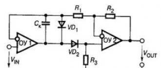
The figure shows a schematic diagram of a multimeter. This is the easiest option. As you can see, it has three shunt resistors with nominal values of 0.5 ohms, 4.6 ohms and 46.3 ohms. In milliammeter mode, it provides, when connected to the appropriate terminals, the measurement of current in three ranges: 300 mA, 30 mA and 3 mA. Shunts are needed to protect the multimeter and measure current in various ranges.

Additional resistors with a nominal value of 950 Ohm, 10 kOhm and 100 kOhm are designed to measure voltage in three ranges: 3 V, 30 V and 300 V. The resistance is measured when connected to the Rx contacts of the measured load. Before measurement, with shorted contacts of the measuring probes, the variable resistor R3 is set to zero on the resistance measurement scale. This tester is designed to measure DC current only. In order for it to measure alternating current, rectifier diodes must be introduced into the circuit. This is due to the fact that the magnetoelectric mechanism of the microammeter, due to its principle of operation, can only measure direct current.
The circuit diagram of the multimeter, if it is a pointer, changes slightly from device to device. There may be other resistance values due to the use of different microammeters, but the essence will not change. Therefore, it is easy to repair them, unlike digital testers.
Structural diagram of a digital device
Currently, most multimeters produced by the industry are digital. It is understandable. Thanks to the use of a modern element base with a high input resistance, it became possible to create multi-bit accurate analog-to-digital converters of an electrical signal. This, in turn, made it possible to reduce the measurement error, and the use of digital indication provided easy reading of information. In the case of pointer multimeters, this is difficult, since with an error of 0.2% or more, it will be almost impossible to read an accurate reading due to the dense arrangement of divisions on the scale.

The schematic diagram of a multimeter based on integrated circuits is highly dependent on the type of microcircuits used, therefore, to analyze the principle of operation of the device, it is more convenient to use the block diagram, which is the same for all digital testers. The figure shows a block diagram of a digital multimeter. It shows how the measurements of direct and alternating currents, as well as resistances, take place.
Attenuator and operational amplifier
An attenuator is a device in a circuit that reduces the input signal by a certain number of times so that it is in a normalized range, for example, 0-1 mV. Depending on the specific implementation, the range may be different.

The operational amplifier is very sensitive and has a large gain. It responds to units of microvolts at its input, and the gain allows you to set from one to several thousand. At the same time, it has a huge input impedance, which is why it practically does not introduce errors. Based on it, you can create very accurate multimeters and other measuring devices. So, when a voltage from the attenuator enters the input of the operational amplifier, it will amplify it by a specific number of times, and also will not exceed the permissible limits.
ADC
The input of the analog-to-digital converter (ADC) will receive a signal that does not exceed the conversion range. Pre-amplification was required so that the converter could digitize it and display it on a digital indicator. The circuits of analog-to-digital converters are very diverse, and some of them are made in the form of a separate microcircuit, which is very convenient when creating compact multimeters.

Precision rectifier and switch
When measuring alternating currents, a precision rectifier is additionally used. When it is necessary to measure the resistance, it is connected to a converter, which is a reference current generator with dividers. This current passes through the measured resistance, a voltage drop occurs on it. This fall is amplified, digitized and displayed on a digital indicator.
For any measurements, the signals come through the switch. It can be mechanical or electronic. Standalone handheld multimeters use a mechanical switch.
Although the circuit diagram of the digital type multimeter is not presented, by analyzing the device structure, you can find differences between it and the analog type.
Arrow multimeters, in order to measure any parameter, convert it into current strength and then only measure it. And digital testers, using the advantages of operational amplifiers, their huge internal resistance, convert all incoming signals into voltage and then only take measurements.
Basic designations
Most multimeters look like small boxes with a dial or LCD screen on top. The designations on the multimeter are almost the same and do not depend on the type of instrument and circuit. So, below the screen is a switch for measurement modes. Icons are displayed around the type and range of the measured value:

On the right side there are three slots. The top one, with the number 10A, is used when measuring direct current up to 10 amperes. The average is used for measurement in all other cases. The lower socket for connecting a neutral wire, a ground sign is shown next to it, as in the diagram. The number of ranges and their limits, the types of measured values may differ, but will generally be the same.
The device and appearance are also affected by additional features provided by the manufacturer. So, now there are testers with built-in current clamps. They allow you to measure the current without breaking the conductor, it is enough to clasp it with clamps.
In addition to the multimeter, the scope of delivery includes probes and an instruction manual. It usually contains a circuit diagram, technical specifications, rules for using the device and safety requirements.
MULTIMETER DIAGRAM
There are currently three main modelsdigital multimeters, these are dt830, dt838, dt9208 and m932. The first model to appear on our markets dt830.
Digital multimeter dt830
Constant pressure:
Limit: 200mV, Resolution: 100uV, Accuracy: ±0.25%±2
Limit: 2V, Resolution: 1mV, Accuracy: ±0.5%±2
Limit: 20V, Resolution: 10mV, Accuracy: ±0.5%±2
Limit: 200V, Resolution: 100mV, Accuracy: ±0.5%±2
Limit: 1000V/600V, Resolution: 1V, Accuracy: ±0.5%±2
AC voltage:
Limit: 200V, Resolution: 100mV, Accuracy: ±1.2%±10
Limit: 750V/600V, Resolution: 1V, Accuracy: ±1.2%±10
Frequency range from 45Hz to 450Hz.
D.C:
Limit: 200uA, Resolution: 100nA, Accuracy: ±1.0%±2
Limit: 2000uA, Resolution: 1uA, Accuracy: ±1.0%±2
Limit: 20mA, Resolution: 10uA, Accuracy: ±1.0%±2
Limit: 200mA, Resolution: 100uA, Accuracy: ±1.2%±2
Limit: 10A, Resolution: 10mA, Accuracy: ±2.0%±2
Resistance:
Limit: 200Ω, Resolution: 0.1Ω, Accuracy: ±0.8%±2
Limit: 2KΩ, Resolution: 1Ω, Accuracy: ±0.8%±2
Limit: 20KΩ, Resolution: 10Ω, Accuracy: ±0.8%±2
Limit: 200KΩ, Resolution: 100Ω, Accuracy: ±0.8%±2
Limit: 2000KΩ, Resolution: 1KΩ, Accuracy: ±1.0%±2
Output voltage on bands: 2.8V
hFE transistor test:
I, constant: 10μA, Uk-e: 2.8V±0.4V, hFE measurement range: 0-1000
diode test
Test current 1.0mA±0.6mA, test U 3.2V max.
Polarity: automatic, Overload indication: "1" or "-1" on the display, Measuring rate: 3 meas. per second, Power: 9V.The price is about 3.

More advanced and multifunctional modeldigital multimeter, becamedt838. Along with the usual features, here added tobuilt-in 1 kHz sine wave generator.
Digital multimeter dt838
Number of measurements per second: 2
DC voltage U= 0.1mV - 1000V
AC voltage U~ 0.1V - 750V
DC current I= 2mA - 10A
AC frequency range current 40 - 400Hz
Resistance R 0.1 ohm - 2 megohm
Input resistance R 1 MΩ
Transistor gain h21 up to 1000
Call mode< 1 кОм
Power supply 9V, Krona VTS
The price is about 5 ye.

The internal and external stuffing is almost identical to the dt830 model. A similar feature is the low reliability of moving contacts.

Currently, one of the most advanced models isdigital multimeter m932 . Features: automatic range selection and non-contact search for static electricity.
Digital multimeter m932
Specifications of the digital multimeter m932 :
DC VOLTAGE Measurement limits 600 mV; 6; 60; 600; 1000 V
Accuracy ± (0.5 % + 2 digits)
Max. resolution 0.1 mV
In. resistance 7.8 MΩ
1000 V input protection
VARIABLE VOLTAGE Limits of measurements 6; 60; 600; 1000 V
Max. resolution 1 mV
Frequency band 50 - 60 Hz
In. impedance 7.8 MΩ
1000 V input protection
DIRECT CURRENT Measurement limits 6; 10 A
Accuracy ± (2.5 % + 5 digits)
Max. resolution 1 mA
ALTERNATING CURRENT Measurement limits 6; 10 A
Max. resolution 1 mA
Frequency band 50 - 60 Hz
RMS measurement - 50 - 60 Hz
Input protection Fuse 10 A
RESISTANCE Measurement limits 600 Ohm; 6; 60; 600 kOhm; 6; 60 MΩ
Accuracy ± (1% + 2 digits)
Max. resolution 0.1 ohm
600 V input protection
CAPACITY Limits of measurements 40; 400 nF; 4; 40; 400; 4000uF
Accuracy ± (3% + 5 digits)
Max. resolution 10 pF
600 V input protection
FREQUENCY Measurement limits 10; 100; 1000 Hz; 10; 100; 1000 kHz; 10 MHz
Accuracy ± (1.2 % + 3 digits)
Max. resolution 0.001 Hz
600 V input protection
COEF. PULSE FILL Measuring range 0.1 - 99.9 %
Accuracy ± (1.2 % + 2 digits)
Max. resolution 0.1%
TEMPERATURE Measurement range - -20°C - 760°C (-4°F - 1400°F)
Accuracy ± 5°C/9°F)
Max. resolution 1°C; 1°F
600 V input protection
P-N TEST Max. test current 0.3 mA
Test voltage 1 mV
600 V input protection
CIRCUIT RINGING Threshold< 100 Ом
Test current< 0.3 мА
600 V input protection
GENERAL DATA Max. display number 6000
Linear scale 61 segments
Measuring speed 2 per second
Auto power off after 15 minutes
Power supply 9 V type "Krona"
Operating conditions 0°С - 50°С; rel. humidity: no more than 70%
Storage conditions -20°С - 60°С; rel. humidity: no more than 80%
Dimensions 150 x 70 x 48 mm
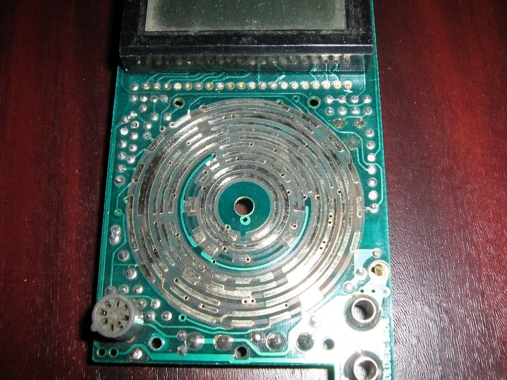
The fact that such a meter is necessary for a radio amateur not only learned from others, but he himself felt when he undertook to repair an old amplifier - here you need to reliably check each electrolyte on the board and find it that has become unusable or make 100% of their replacement. Selected check. And I almost bought an advertised device called "ESR - mikro" via the Internet. It stopped what was painfully praised - "over the edge." In general, he decided to take action on his own. Since I didn’t want to sway, I chose the simplest, if not primitive, scheme, but with a very good (careful) description. I delved into the information and, having some inclination for drawing, began to breed my own version of the printed circuit board. To fit in the case from a thick felt-tip pen. It did not work out - not all the details were included in the planned volume. Thought about it, drew a signet in the image and likeness of the author, etched and collected. Collect succeeded. Everything came out very well thought out and neat.
But the probe did not want to work, no matter how much he fought with it. And I didn't want to give up. For a better perception of the scheme, I redrawn it in my own way. And so "native" (for two weeks of ordeals), it became more understandable visually.
Schematic diagram of the ESR meter

And I completed the printed circuit board in a cunning way. She became “two-sided” - on the second side she placed the details that did not fit on the first. For ease of solution, the difficulties that arose, I placed them in a "canopy". There is no time for elegance - a probe is needed.

I etched the printed circuit board and soldered the parts. This time I put the microcircuit on the socket, adapted the connector for power supply, which can be securely fixed on the board by soldering, and the case can later be “hung” on it. But the tuning resistor, with which the probe worked best, I found only this one - far from miniature.

The reverse side is the fruit of pragmatism and the pinnacle of asceticism. Something can be said here only about the probes, despite the elementary design, they are quite convenient, and the functionality is generally beyond praise - they are capable of contact with an electrolytic capacitor of any size.

I put everything in an improvised case, the place of attachment is the threaded connection of the power connector. On the case, respectively, went minus power. That is, he is grounded. Whatever it is, but protection from interference and interference. The trimmer was not included, but it is always “at hand”, it will now be a potentiometer. A plug from a radio broadcast speaker, once and for all, will avoid confusion with multimeter sockets. Powered by a laboratory PSU, but with the help of a personal wire with a plug from a Christmas tree garland.

And it, this unsightly miracle, took it and started working, and right away and as it should. And there are no problems with adjustment - corresponding to one ohm, one millivolt is set easily, approximately in the middle position of the regulator.

And 10 ohms corresponds to 49 mV.

A good capacitor corresponds to approximately 0.1 ohm.

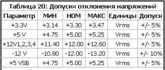
Faulty capacitor, corresponds to more than 10 ohms. The probe coped with the task, faulty electrolytic capacitors on the board of the device being repaired were found. You can find all the details regarding this scheme in the archive. The maximum allowable ESR values for new electrolytic capacitors are shown in the table:

And some time later, I wanted to give the prefix a more presentable look, but the learned postulate “the best is the enemy of the good” did not allow me to touch it - I will make another one, more elegant and perfect. Additional information, including the diagram of the original device, is available in the appendix. He told about his troubles and joys Babay.
Discuss the article ADDITION TO THE MULTIMETER ESR METER
Start
Yes, this topic has been discussed many times, including here. I have compiled two versions of the scheme Ludens and they have proven themselves very well, however, all the options previously proposed have drawbacks. Instrument scales with dial indicators are very non-linear and require many low-resistance resistors for calibration, these scales must be drawn and inserted into the heads. Instrument heads are large and heavy, fragile, and the cases of small-sized plastic indicators are usually soldered and they often have a small scale. The weak point of almost all previous designs is their low resolution. And for LowESR capacitors, it is just necessary to measure hundredths of an ohm in the range from zero to half an ohm. Devices based on microcontrollers with a digital scale were also proposed, but not everyone deals with microcontrollers and their firmware, the device turns out to be unreasonably complex and relatively expensive. Therefore, in the Radio magazine they made a reasonable rational scheme - any radio amateur has a digital tester, and it costs a penny.
I made minimal changes. Housing - from a faulty "electronic choke" for halogen lamps. Power - battery "Krona" 9 Volt and stabilizer 78L05. I removed the switch - it is very rare to measure LowESR in the range up to 200 Ohms (if I feel like it, I use a parallel connection). Changed some details. Chip 74HC132N, transistors 2N7000(to92) and IRLML2502(sot23). Due to the increase in voltage from 3 to 5 volts, there was no need to select transistors.
During testing, the device worked normally from a fresh battery voltage of 9.6 V to a fully discharged 6 V.
In addition, for convenience, I used smd resistors. All smd elements are perfectly soldered with the EPSN-25 soldering iron. Instead of a serial connection R6R7, I used a parallel connection - it’s more convenient, on the board I provided for connecting a variable resistor in parallel with R6 to adjust zero, but it turned out that “zero” is stable over the entire range of voltages I indicated.

The surprise was that in the design "developed in the magazine" the polarity of the VT1 connection was reversed- the drain and the source are mixed up (correct if I'm wrong). I know that transistors will work even with this inclusion, but such errors are unacceptable for editors.
Total
This device has been working for me for about a month, its readings when measuring capacitors with ESR in units of ohms coincide with the device according to the scheme Ludens .It has already been tested in combat conditions, when my computer stopped turning on due to the capacitances in the power supply, while there were no obvious signs of “burnout”, and the capacitors were not swollen.
The accuracy of readings in the range of 0.01 ... 0.1 Ohm made it possible to reject dubious ones and not to throw away old soldered capacitors, but having a normal capacity and ESR. The device is easy to manufacture, parts are available and cheap, the thickness of the tracks allows them to be drawn even with a match.
In my opinion, the scheme is very successful and deserves repetition.
Files
Printed circuit board:▼ 🕗 25/09/11 ⚖️ 14.22 Kb ⇣ 668 Hello reader! My name is Igor, I'm 45, I'm a Siberian and an avid amateur electronics engineer. I came up with, created and maintain this wonderful site since 2006.
For more than 10 years, our magazine exists only at my expense.
Good! The freebie is over. If you want files and useful articles - help me!
Every radio amateur has a simple and reliable multimeter in his arsenal, but sometimes its capabilities are not enough. Then home-made circuits come to the rescue - prefixes to the multimeter, which will help the novice electronics engineer in his amateur radio practice
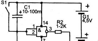
The design of a homemade set-top box consists of an adjustable boost converter powered by a 5 V power supply or USB; Rectangular pulse generator DD1.1 with a repetition rate of 15 kHz; A differentiating chain on SZ and VT1 and an inverter on elements DD1.2-DD1.4.

Rectangular pulses from the DD1.1 generator pass through the differentiating chain to the DD1.2 inputs. By opening VT1 more strongly, you can “reduce” the pulses at its inputs. The inverted pulses are fed through the resistor R3 to the base of the transistor VT2. That is, if there is a unit at the outputs of the inverter, the transistor VT2 is open and current begins to flow through the inductor L1, and energy accumulates in its magnetic field. At "zero", the transistor VT2 is closed and a self-induction voltage pulse is formed on L1, which is rectified by the VD1 diode and smoothed by the capacitor C5. The longer the pulse coming to VT2, the higher the energy level accumulated in the inductor and the higher the voltage from the rectifier output.
In the initial state, the duty cycle of the generator pulses is about two and the voltage at the output of the rectifier is maximum. It enters VT1 through a divider on resistors R2-R4, VT1 opens and the duration of the pulse going to the base of VT2 becomes smaller, as does the voltage at the output of the rectifier. Thus, the voltage is stabilized at the output of the rectifier in the range of 55-60 V. The output voltage can be regulated by resistor R4.
To check the zener diode a multimeter is connected to the prefix in direct current mode. The zener diode under test is connected to the XS1 sockets, the SA2 switch is set to the “Stable” position. If the zener diode is working and its stabilization voltage does not exceed 50 V, the current passing through it increases and the HL1 LED lights up, the VT1 transistor will open even more and the voltage at the rectifier output will decrease. In this case, the voltage on the zener diode will correspond to the stabilization voltage, which we measure with a multimeter. Since we know the polarity, it is easy to understand the purpose of the zener diode pins. If you connect a zener diode in direct turn-on, then VT1 will open completely, and the rectangular pulses will stop coming to DD1.2 and the rectifier is powered by a 5 volt power supply.
To check the dinistor it is connected to connector XS2, the voltage to which is supplied through the RC circuit R6-C7 or R7-C6. In the initial state, SA1 is switched to the "Check" mode, and SA2 is switched to the "Dynamic" mode. If the dinistor is working properly, it, together with the R6-C7 RC circuit, is part of a relaxation oscillator with a pulse repetition rate of several hertz. As soon as the voltage across the capacitor C7 reaches the opening level of the dinistor. It will quickly discharge through the resistor R5 and the LED HL1, which will flash briefly. Due to the fact that the pulse repetition rate is low, the capacitor C4 is not able to maintain a constant voltage at the base of VT1, so the voltage across the rectifier is unstable. This mode is well suited for checking the performance of the dinistor, but if the opening level of the dinistor is greater than 55 V, the relaxation generator no longer works.
To measure the opening level of the dinistor, the XS2 connector is switched to the R7-C6 circuit. In this case, the pulse repetition rate in the relaxation oscillator increases at least several times, and the capacitor C4 calmly maintains the required voltage on the transistor VT1. And it remains open, so the output voltage of the rectifier corresponds to the opening voltage of the dinistor. That is what we can measure with our multimeter.

Used radio components are shown in the diagram, if they are missing, use amateur radio manuals to replace them. It is desirable to use an ultra-bright LED. Choke type RLB0608, you can use homemade.
The design of the printed circuit board is shown in the figure below, for its self-production I recommend using
See also an alternative multimeter attachment for
In modern circuits, the role of capacitors has increased markedly, because both the power and frequency of operation of devices have increased. And therefore it is very important to check the ESR of all capacitors before assembling the circuit or during the diagnosis of a malfunction.
Equivalent Series Resistance - equivalent series resistance is the sum of series-connected ohmic resistances of the leads and electrolyte contacts with electrolytic capacitor plates.
The principle of operation of the prefix to the multimeter is as follows. A triangular-shaped voltage is applied to the measured capacitance, while the current passing through it has the shape of a meander, and its amplitude is proportional to the measured capacitance. In the case of measuring the inductance, a triangular-shaped current is passed through it, the voltage drop across the inductance has the shape of a meander and is proportional to its value. For more details, see the magazine circuitry March 2003.
In amateur radio practice, it is sometimes necessary to measure low resistances, the value of which is below 1 Ohm, for example, in the case of checking transformer windings for short circuits, relay contacts, various shunts,. How to carry out the measurement of low resistances in miliomas or microohms? As is known from the electrical engineering course, the measurement of resistances is based on the effect of converting their value into current or voltage.
This attachment scheme allows you to turn an ordinary multimeter into a simple dosimeter, which is very convenient for domestic use and effective.
As in most designs, the main element in this attachment to the multimeter is the SBM-20 Geiger counter, and any other can be adapted. The indicator is a multimeter DT9208A or with a similar frequency measurement function.
Since the voltage of the Geiger counter is over 400 volts, boost converter. It is made as a blocking generator on the radio components VT1, T1, C1, C2 and R1. With step-up winding transformer T1 pulse voltage follows the rectifier, on the diodes VD1, VD2 and capacitance SZ. The converter raises the voltage to the level of 420...460 V. The cathode of the SBM-20 sensor is connected through a circuit formed by parallel connection of the multimeter and capacitor C4.

When radioactive passes through the sensor, inside it is carried out gas ionization and an electrical impulse is generated at the output.
Manufactured on armored core type B22, ferrite 2000NM. III winding consists of 700 turns, PEV-2 wire with a diameter of 0.1 mm. In the process of winding, every 100 turns we lay a layer of transformer paper or similar insulation. After winding, we isolate the winding again. Two more windings I and II are wound on top of it with a double folded wire of 14 turns each, a PEV-2 wire with a diameter of 0.2 and 0.4 mm. The midpoint will be the beginning of winding I and the end of II.