The widespread and low cost of the Arduino platform and various Robotlatform allowed fans to create radio-controlled cars for every taste. And the wide distribution of smartphones made it possible to use them as controllers of these machines. The main problem for many ARDUINO lovers is the lack of experience in programming under Android. Today I will tell you how it is easy to solve this problem using the Wednesday of the visual development of Android applications App Inventor 2.
Building any typewriter should be started with "iron", so I will briefly describe what I used for your typewriter:
arduino Nano.
bluetooth Module HC-05
Z-MINI MOTOR SENSOR SHIELD L293D
2wd Motor Chassis
The configuration of "iron" does not play a large role in this project, so the chassis, shield and the Arduino itself can be replaced by any counterparts.
Now let's go to the creation of the Android application. App Inventor - Wednesday of Android Applications, works from the browser. We go to the site, allow access to your account to Google, press the "CREATE" button and create a new project. In the new project, the Drag and Drop project creates 4 buttons to select the direction of movement and one for connecting to our Bluetooth module. Like that:

Now it remains to compile the application by clicking on the "Build" button.
With the writing of Sketch, I think the lovers of Arduino will not have problems, I will only say that you can choose from ready-made sketches where the typewriter is controlled from the computer by SIREAL port. I used this
sketch
int val;
int in1 \u003d 4;
int in2 \u003d 7;
int e EN1 \u003d 6;
int e EN2 \u003d 5;
Void setup ()
{
Serial.begin (9600);
Pinmode (In1, Output);
Pinmode (In2, Output);
PINMODE (EN1, OUTPUT);
Pinmode (EN2, OUTPUT);
}
void loop ()
{
if (serial.available ())
{
Val \u003d serial.read ();
// ask a move forward
if (Val \u003d\u003d "w") // When you press the "W" key
{
// Conclusions are configured according to the work of Motor Shield "A
// Motors are spinning forward
DigitalWrite (EN1, HIGH);
DigitalWrite (EN2, HIGH);
DigitalWrite (IN1, HIGH);
DigitalWrite (IN2, HIGH);
}
// Specify the movement back
if (val \u003d\u003d "s")
{
DigitalWrite (EN1, HIGH);
DigitalWrite (EN2, HIGH);
DigitalWrite (In1, Low);
DigitalWrite (In2, Low);
}
// Set the movement to the right
if (Val \u003d\u003d "D")
{
DigitalWrite (EN1, HIGH);
DigitalWrite (EN2, HIGH);
DigitalWrite (IN1, HIGH);
DigitalWrite (In2, Low);
}
// Set the movement to the left
if (val \u003d\u003d "a")
{
DigitalWrite (EN1, HIGH);
DigitalWrite (EN2, HIGH);
DigitalWrite (In1, Low);
DigitalWrite (IN2, HIGH);
}
// Stop Mode
// When you reached the keys in the program in the port snugging "T"
if (Val \u003d\u003d "T") // When the "T" key is pressed.
{
// ENABLE conclusions are attracted to minus, the motors do not work
DigitalWrite (EN1, LOW);
DigitalWrite (EN2, LOW);
}
}
}
So, here I got the machine:

Those who like design in applications may change a little. It is not difficult to describe in detail how to do it, it's not difficult to figure it out. I will only say that for this basically you need to use.png files, instead of .jpeg that do not support transparent background. For example, to make such a design for half an hour or an hour can any unprepared person:

P.S. For those who have not come across the development of applications in the App Inventor 2, I made more detailed guide to develop this application (you need to go to youTube to view).
P.P.S. Collection of more than 100 educational materials on Arduino for beginners and pros
There are also sources for Android and other helpful information. In this article, I will show the CxEmcar assembly for the Arduino platform. You can use almost any Arduino-compatible fee as Arduino fee: Uno, Nano, Mega, Leonardo and even on the basis of STM32 - Arduino Due. I used the ARDUINO NANO V3 scarf acquired on eBay for $ 9.
Scheme aRDUINO connectivity To Bluetooth Module HC-06 and L298N Engine Drive:
In the diagram I used the jumper (on the JMP1 scheme), because When the Bluetooth module is connected, it was impossible to load the sketch in Arduino. At the time of the firmware, the bluetooth module is de-energized with removing the jumper.
As a platform, I used a small RC DIY platform purchased for $ 25. The platform itself is an aluminum base, where two engines are attached, gearbox and 4 cardan transmission for 4-wheels. From above, on 3 racks there is a batch fee.

The platform is no high quality manufacturing. After I collected it, I tried to connect food - the engine did not even move, a lot of distortions, flaws, etc. It was necessary to disassemble everything, to loosen the attachments somewhere, somewhere to appeal, everything is well lubricating, and also removed 2 cardan from the front axle. It turned out a rear-wheel drive version.
After that, I soldered a Bluetooth module to Arduino and led the status LED for it. On the varieties of Bluetooth modules, their connection to Arduino, work with them, etc. You can read in this article :. The HC-06 module placed 10mm in the heat shrink tube. The Bluetooth state LED with a current-barreler resistor was also placed in a shrinking, but more subtle - 5mm.

In the Makeground, which went along with the platform, I drilled holes and secured the L298N engine driver. Arduino board attached with bilateral tape.

Between the aluminum platform of the machine and macatetie I posted 3 Li-PO batteries 3.7V 1100 mA * h. Power of the controller and separate engines: Arduino is powered by one battery 3.7V, and the Motors and the L298N driver from two successively connected batteries 3.7B. There are two 2-position power switches - in one position the power goes from batteries to consumers, in another position on the charging terminals.
Stock Foto Typewriters on recharge:

Software
The program has written in Arduino IDE 1.01. The program code I tried to comment well, but if there were questions - ask forum, c.
#Include "eeprom.h" #define D1 2 // Direction Rotation of engine 1 #define M1 3 // PHM output for motor control 1 (left) #define D2 4 // Direction Rotation of engine 2 #define M2 5 // Rotation direction Engine 2 (right) #define Horn 13 // Extra. Channel 1 connected to 13 Pin // # Define AutoFF 2500 // Number of milliseconds through which the robot stops when loss of #define CMDL "L" // UART command for the left motor #Define CMDR "R" // UART command for the right Engine #Define CMDH "H" // UART command for extra. Channel 1 (For example, the Horn signal) #define CMDF "F" // UART command to work with EEPROM memory MK to store #define CMDR settings "R" // UART command to work with EEPROM MC memory for storing settings (reading) # DEFINE CMDW "W" // UART command to work with EEPROM memory MK to store settings (recording) Char IncomingByte; // Incoming data Char L_Data; // String array for the left motor data L BYTE L_INDEX \u003d 0; // CHAR R_DATA array index; // String array for the right motor data R.index \u003d 0; // CHAR H_DATA array index; // String array for extra. Channel byte H_INDEX \u003d 0; // Index of the H CHAR F_DATA array; // String data array to work with EEPROM BYTE F_INDEX \u003d 0; // Array Index F Char Command; // Team: Transmission of coordinates R, L or end of the string Unsigned Long CurrateTime, Lasttimecommand, AutoFF; Void setup () (serial.begin (9600); // Pinmode port initialization (Horn, Output); // additional channel Pinmode (D1, Output); // Exit to specify the direction of rotation of the Pinmode engine (D2, OUTPUT); // Exit to specify the direction of rotation of the engine /*eeprom.write(0,255); EEPROM.WRITE (1,255); EEPROM.WRITE (2,255); EEPROM.WRITE (3,255); * / Timer_init (); // Initialize the program timer) Void Timer_init () (uint8_t sw_autooff \u003d eeprom.read (0); // read with the EEPROM parameter "is included if the machine stops during loss of communication" if (SW_Autooff \u003d\u003d "1") (/ / If the stop timer is enabled Char Var_Data; var_data \u003d eeprom.read (1); var_data \u003d eeprom.read (2); var_data \u003d eeprom.read (3); autooff \u003d atoi (var_data) * 100; // Variable autotl. for storage of the number of MS) \u200b\u200belse if (SW_Autooff \u003d\u003d "0") (automooff \u003d 999999;) else if (SW_Autooff \u003d\u003d 255) (automooff \u003d 2500; // If nothing is written in EEPROM, then by default 2.5 seconds) currenttime \u003d millis (); // Read the time that has passed since the program starts) void loop () (if (serial.available ()\u003e 0) (// if UART has arrived incomingbyTe \u003d serial.read (); // read IF byte (IncomingByte \u003d\u003d CMDL) (// if data for motor l command \u003d cmdl came (// Current MemSet command (L_DATA, 0, SIZEOF (L_DATA)); // Cleaning an array L_INDEX \u003d 0; // Reset the array index ) ELSE IF (IncomingByt e \u003d\u003d cmdr) (// If the data for the motor R COMMAND \u003d CMDR came; MEMSET (R_DATA, 0, SIZEOF (R_DATA)); R_index \u003d 0; ) ELSE if (incomingByte \u003d\u003d CMDH) (// If data for additional channel 1 Command \u003d CmDH; MEMSET (H_DATA, 0, SIZEOF (H_DATA)); H_INDEX \u003d 0;) ELSE iff (incomingbyte \u003d\u003d cmdf) ( // if data came to work with Command \u003d CMDF; MEMSET (F_DATA, 0, SIZEOF (F_DATA)); F_INDEX \u003d 0;) ELSE If (incomingByte \u003d\u003d "\\ R") Command \u003d "E"; // end of the ELSE IF string (incomingbyte \u003d\u003d "\\ t") command \u003d "t"; // End of the string for the IF memory commands (COMMAND \u003d\u003d CMDL && incomingByte! \u003d CMDL) (L_Data \u003d IncomingByte; // We save each accepted byte in an L_INDEX ++ array; // Increase the current array index) ELSE if (Command \u003d\u003d CMDR && IncomingByte! \u003d CMDR) (R_Data \u003d IncomingByte; R_INDEX ++;) ELSE If (Command \u003d\u003d CMDH && IncomingByte! \u003d CMDH) (H_Data \u003d IncomingByte; H_INDEX ++;) ELSE If (Command \u003d\u003d CMDF && IncomingByte! \u003d CMDF) (F_Data \u003d incomingByte; F_INDEX ++;) ELSE If (Command \u003d\u003d "E") (// If the end of the Control4WD string (ATOI (L_DATA), ATOI (R_DATA), ATOI (H_DATA)); Delay (10);) ELSE if ( Command \u003d\u003d "T") (// If you took the end of the string to work with Flash_op memory (F_DATA, F_DATA, F_DATA, F_DATA, F_DATA);) LastTimeCommand \u003d Millis (); // Read the current time that has passed since the program starts) if (Millis ()\u003e \u003d (LasttimeCommand + Autooff)) (// compare the current timer with a variable LastTimeCommand + AutoFF Control4WD (0,0,0); // Stand the machine) ) Void Control4WD (int mleft, int mright, uint8_t horn) (bool directionl, directionr; // Rotation direction for L298n byte Valuel, Valuer; // Value M1, M2 (0-255) IF (MLEFT\u003e 0) (Valuel \u003d MLEFT; directionl \u003d 0;) ELSE if (mleft< 0){ valueL = 255 - abs(mLeft); directionL = 1; } else { directionL = 0; valueL = 0; } if(mRight > 0) (VALUER \u003d MRIGHT; DirectionR \u003d 0;) ELSE If (mright< 0){ valueR = 255 - abs(mRight); directionR = 1; } else { directionR = 0; valueR = 0; } analogWrite(M1, valueL); // задаем скорость вращения для L analogWrite(M2, valueR); // задаем скорость вращения для R digitalWrite(D1, directionL); // задаем направление вращения для L digitalWrite(D2, directionR); // задаем направление вращения для R digitalWrite(HORN, Horn); // дополнительный канал } void Flash_Op(char FCMD, uint8_t z1, uint8_t z2, uint8_t z3, uint8_t z4){ if(FCMD == cmdr){ // если команда чтения EEPROM данных Serial.print("FData:"); // посылаем данные с EEPROM Serial.write(EEPROM.read(0)); // считываем значение ячейки памяти с 0 адресом и выводим в UART Serial.write(EEPROM.read(1)); Serial.write(EEPROM.read(2)); Serial.write(EEPROM.read(3)); Serial.print("\r\n"); // маркер конца передачи EEPROM данных } else if(FCMD == cmdw){ // если команда записи EEPROM данных EEPROM.write(0,z1); // запись z1 в ячейку памяти с адресом 0 EEPROM.write(1,z2); EEPROM.write(2,z3); EEPROM.write(3,z4); timer_init(); // переинициализируем таймер Serial.print("FWOK\r\n"); // посылаем сообщение, что данные успешно записаны } }
The code uses a library to work with EEPROM AVR memory. One setting is stored in memory: the amount of milliseconds through which the machine stops when loss of communication. You can write this setting "Hard" to register in the program, to do this, unset the line #define AutoFF 2500 (where 2500 is Milliseconds). After that, the Flash_OP function can be deleted, it will also be necessary to make small edits into the code responsible for receiving commands to work with EEPROM memory.
But with the purchase of a ready-made full-fledged robot on the basis of this fee. For kids elementary school or preschool age such ready projects Arduino. even preferable, because "The unexplus" fee looks boring. Such a way Suitable for those whom the electrical schemes are not particularly attracted.
By purchasing the working model of the robot, i.e. Actually ready high-tech toy, you can wake up interest in independent design and creating robots. Having played in such a toy and deraiding in how it works, you can proceed to improving the model, disassemble everything into parts and start collecting new projects on Arduino, using a platform released, drives and sensors. The openness of the Arduino platform allows one of the same component parts Masite new toys.
We offer a small review of the finished robots on the Arduino board.
Machine on Arduino, controlled via Bluetooth
Machine controlled via Bluetooth, worth a little less than $ 100. Comes in disassembled form. In addition to the housing, motor, wheels, lithium batteries and chargerwe receive the Arduino Uno328 board, the motor controller, Bluetooth Adapter, Remote remote control etc.
Video with this and one more robot:
More detailed description Toys and the opportunity to buy on the website of the online store DealExtreme.
Arduino Robot Turtle
Kit for assembling robot turtle worth about $ 90. There is not enough shell, everything else necessary for the life of this hero, complete: Arduino Uno, servo drives, sensors, tracking modules, IR receiver and remote control, battery.

A turtle can be bought on DealExtreme, a similar cheaper robot on Aliexpress.
Crawler Machine on Arduino, Managed from Cell Phone
Tracked car controlled by Bluetooth with cell phone , worth $ 94. In addition to the caterpillar database, we receive the Arduino Uno board and the extension board, Bluetooth fee, battery and charger.
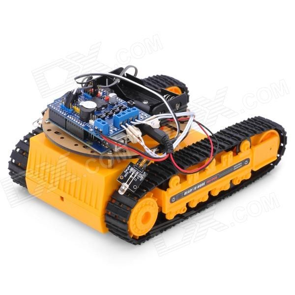
The tracked car can also be bought on DealExtreme website, there is a detailed description. Maybe more interesting iron Arduino-tank on Aliexpress
Arduino car passing labyrinths
Car passing labyrinths, worth $ 83. In addition to engines, Arduino Uno cards and other necessary fitness modules and obstacle coupling modules.

Ready Robot or Robot Frame
In addition to the use of ready-made kits to create Arduino robots, you can buy a separate frame (body) of the robot - it can be a platform on wheels or caterpillage, humanoid, spider and other models. In this case, the filling of the robot will have to do it yourself. An overview of such buildings is given in ours.
Where else to buy finished robots
In the review we chose the cheapest and interesting in our opinion ready-made Arduino-robots from Chinese online stores. If there is no time to wait for the parcel from China - a large selection of ready-made robots in online stores Amperka and Dessy. Low prices And quick delivery offers online store Robstore. List of recommended shops.
Perhaps you will also be interested in our project reviews on Arduino:

Training Arduino.
Do not know where to start learning Arduino? Think that you are closer - the assembly of your own simple models and gradually their complications or acquaintance with more complex, but ready-made solutions?
Main source of information - EasyElectronics.com
One Arduian is not enough here. Still need:
-Sile modules for motor control and light
- Module power source
- Communication module
Arduin is only brains, and quite crime.
The issue of the compatibility of the motor with Arduian does not make much sense. The fact is that directly to Arduin is practically no motor, it is impossible, it burns.
Between Arduina and the motor will be a mediator - a power module. Due to this, Arduin is actually compatible with any engine.
Regarding where to buy "- either online shopsor shops electronic components. Look for search in your city. In large cities you can buy everything in one place, but overpaying times in 1.5-5 compared to Ali.
How would I do the machine.
As a brain high level And communication module, I would take something from ESP32 or ESP8266. The first works with Bluetooth and WiFi. The second only works with Wi-Fi.
Arduin will come as a periphery controller. But! I would not become a roar of a garden from a pile of boards and wires - most likely, it won't fit into the body of the machine, and if it gets, it will be very scary.
Therefore, all the components of this design I would place on a specially designed pCBwhich later in my order will produce some kind of resonate.
1) Depends on your location and assumptions in a small overpayment. You can, everything you need to order from China, if you are ready to expect 14-40 days, which will save a small part of the total amount.
He himself personally ordered the following comrades:
There were no problems, respectively.
2) If it happens, you need two DC engines and one servo. Just drive "DC Motor" and "SERVO".
Examples of issuing:
When choosing a servo, you need to pay attention to gears and of course developing craving. In principle, for a banal toy machine, there is enough first option from the example. But for the future, keep in mind that the bailiff "MG" implies metal gears, which makes in general device More resistant to breakage, although it does not negate them.
To control the entire system, you will also need the so-called "Motor Shield":
The first of the examples given due to the presence of a shift register and two bridges allows you to simultaneously manage four motors. The only thing that will be the problem - meals, because For adequate operation, each is required from 5V, otherwise there may be problems with developed power.
In principle, the second can also be controlled by four wheels at once, connecting them simply in pairs (for turning to use the difference in speeds of the parties). But in your case there will be a second option. Especially he allows the use of high currents than the first.
3) Just acquire LEDs and connect them or directly (not forgetting about resistors) or through any of the chips.
"Diod"
4) Bentally install Arduino IDE and use C / C ++
Resources for study:
P.S. concerning remote accessthen pay attention to the answer of the comrade above
1) Where to buy Arduino himself?
Yes
2) What motors will be compatible with this single pilot? I need a pair of engines for the course of the machine, and so I understand you need a stepping motor for turning the machine.
Any, but for no other engine cannot be connected, a special engine control shield is needed, for example, such. For the rotary mechanism, non-step engines are used, but
Machine on Arduino with Bluetooth Managementm Ot Android phone - This is a very simple, but interesting project on Arduino Uno using the Motor Shield module. On this page, you will learn what components will require for the manufacture of the robot machines on Arduino do it yourself, step-by-step instructions By assembly electrical circuit and you can download everything required programs For Android and Arduino.
Video. Machine on bluetooth control Arduino
For this project, the Motor Shield L293D module was used, two wheels with gearboxes, Arduino Uno, Bluetooth Module HC-05 and two LEDs for headlights. The control is remotely via a Bluetooth signal from a smartphone or tablet. After assembling the model and installing programs, you can turn the machine through the application on the smartphone, go back and forth, turn on and off the headlights.
Machine on Arduino do it yourself
For this project, we will need:
- arduino Uno board;
- Motor Control SHIELD L293D;
- Bluetooth Module HC-05/06;
- two motors with gearboxes and wheels;
- 9V battery (crown);
- 2 resistors and 2 LEDs;
- housing and wheels from the old machine;
- soldering iron, thermal, stationery knife;
- wires, solder and tape.
Machine assembly scheme on Arduino
If you have all the necessary details (in the project you can do without LEDs and resistors), then then we will look at how to make the machine from Arduino do it yourself. To begin with, you should shift to the contacts of the motor's motors and fix them with a tape so that the contacts do not break off. Wires must be connected to M1 and M2 terminals on Motor Shield (the polarity can then be changed).

Power on a Bluetooth Module comes from contacts for servo, in the project, we will not need us. And there is a stabilized voltage of 5 volts on food, which suits us. TX and RX ports will be more convenient to solder the "Mom" connectors, and the Pin0 and Pin1 ports on the Motor Shield plot pins (BLS). Thus, you can easily disable the Bluetooth module from Arduino if you need to download the sketch.
LED control comes from the port "PIN2", here the wire can be soldered directly to the port. If you make several cars with bluetooth, which will be managed at the same time, we recommend making the HC-05 module flashing. The module firmware is done very simply, and then you will no longer be confused by the machine, since each of each will be displayed its unique name on android.
App and sketch for machines on Arduino
After assembling the circuit, download the following sketch for the machine (do not forget to turn off the Bluetooth module from Arduino when downloading) and install the application on the smartphone. All files for the project (AFMOTOR.H library, Sketch for machine and Android application) You can download one archive for a direct link.
#Include.Explanation to the code:
- For testing, you can send commands from a computer via USB;
- Rotation of motors when connected to the battery will be different;
- You can set your rotation speed by motors.

After checking the machine, install the application on your smartphone or tablet. When you first connect to Bluetooth, the HC-05/06 module, you will need to make an android pairing (then the pairing will be performed automatically). If you have any complexity with the connection - read this article.