Now I want to provide you with an interesting option "Manage Arduino-typewriter with a G-sensor on Android smartphone"
In this article, I will tell you how with this service Remotexy is very easy to configure remote control of the platform or machine. We will control the robocatainem with the help of the "Joystick" control, which can work from the G-sensor of your smartphone. At the end of the article you will find a video and you can see what we did.
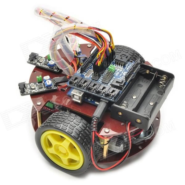
We have collected a very simple two-wheeled trolley to demonstrate to you how to build a system remote control. The following components are used in the trolley (we do not apply for the quality of manufacture, the cart is collected to demonstrate the resource options Remotexy):
- Platform - We were cut out of the sheet material. For simplicity, the fiberboard was used;
- Front wheel - swivel wheel from the chair;
- Motor reducers 2 pcs.;
- Wheels, with axis suitable for motor reducer 2 pcs. Wheels We purchased together with the gearbox motor;
- Battery compartment with switch, on 4th finger batteries (AA type);
- Arduino., we used all the same seeeduino clone;
- Bluetooth HC-06 module;
- Driver Motors on chip L298N;
All items can be ordered on the Chinese website for a penny. True will have to wait a little. but it is better to save than overpay
The electrical part and the connection scheme of all modules of the machine are presented in the following figure.

Management program
Enter the editor on this resource and construct the following control interface:
Install the center of the "Joystick" screen. In the joystick properties, select Install an optional "Enable G Sensor" control. Select the position of the G-sensor switch "NED-Levo". Also in the settings you can change the color to red. In the following joystick, we will control the movement of the machine.
Set the "Switch". Place it left the joystick. You can also change its color. The switch we will control the LED on the Arduino board on Pinea 13.
If you did everything right, you should have about this control interface: 
In the project settings, select the target platform for which we get source "Arduino (SoftWareSerial)." Click the "Get Code" button and download the source code to your computer.
Open the downloaded Skatch in the ARDUINO IDE. Skatch is perfectly compiled without errors. However, in it of course there is no code to manage our machine. Our task to write this code. For sample, we will use the loaded example.
Pay attention to the definition of the structure Remotexy_typedef. in file remotexy.h.. The structure contains fields that are fully appropriate to the control elements installed on the control interface. We see variables joystick_1_x. and joystick_1_y.reflecting the coordinates of X and Y of our joystick, as well as a variable switch_1Reflective switch.
/ * Structure defines all variables of your control interface * / TypeDef Struct (
/ * INPUT VARIABLE * / SIGNED CHAR JOYSTICK_1_X; / * \u003d -100..100 coordinate X position joystick * / signed char joystick_1_y; / * \u003d -100..100 y coordinate position joystick * / unsigned char switch_1; / * \u003d 1 If the switch is turned on and \u003d 0 if disabled * /
/ * Other Variable * / unsigned char connect_flag; / * \u003d 1 If Wire Connected, ELSE \u003d 0 * /
) Remotexy_typedef;
The following is the main program code, which is already built into the management of the engines of our typewriter. You can just copy this code In your sketch, or selectively add the necessary pieces of code into the loaded example.
#Include.
/ * Determine the pins of control of the right motor * /
#Define Pin_motor_right_up 7.
#Define Pin_motor_right_dn 6.
#Define Pin_motor_right_speed 10.
/ * Determine the Left Motor Control Pins * /
#Define Pin_motor_left_up 5.
#Define Pin_motor_left_dn 4.
#Define Pin_Motor_left_speed 9.
/ * Determine the PIN control of the LED * /
#Define Pin_LED 13.
/ * Determine two array with the transfer of pins for each motor * /
unsigned char rightmotor \u003d (pin_motor_right_up, pin_motor_right_dn, pin_motor_right_speed);
unsigned char leftmotor \u003d (pin_motor_left_up, pin_motor_left_dn, pin_motor_left_speed);
/*
Motor speed control
Motor - Link to the Massif of Pins
V - motor speed, can take values \u200b\u200bfrom -100 to 100
*/
Void Wheel (Unsigned Char * Motor, Int V)
{
if (v\u003e 100) v \u003d 100;
IF (V.<-100) v=-100;
if (v\u003e 0) (
DigitalWrite (Motor, High);
DigitalWrite (Motor, Low);
AnalogWrite (Motor, V * 2.55);
}
ELSE if (v<0) {
DigitalWrite (Motor, Low);
DigitalWrite (Motor, High);
AnalogWrite (Motor, (-v) * 2.55);
}
ELSE (
DigitalWrite (Motor, Low);
DigitalWrite (Motor, Low);
AnalogWrite (Motor, 0);
}
}
void setup ()
{
/ * Pins initialization * /
Pinmode (Pin_Motor_Right_UP, Output);
Pinmode (pin_motor_right_dn, output);
Pinmode (pin_motor_left_up, output);
Pinmode (pin_motor_left_dn, output);
Pinmode (PIN_LED, OUTPUT);
/ * Remotexy module initialization * /
Remotexy_init ();
void loop ()
{
/ * Remotexy module event handler * /
Remotexy_Handler ();
/ * manage the LED kick * /
DigitalWrite (PIN_LED, (remotexy.switch_1 \u003d\u003d 0)? Low: High);
/ * manage the right motor * /
Wheel (Rightmotor, remotexy.joystick_1_y - remotexy.joystick_1_x);
/ * manage left motor * /
Wheel (leftmotor, remotexy.joystick_1_y + remotexy.joystick_1_x);
}
At the very beginning, the pins numbers are defined to be used to manage motors. Next Pins are grouped into two arrays, for the right and left motor, respectively. To control each engine through the driver on the L298N chip, it is necessary to use 3 signals: two discrete, indicating the direction of rotation of the motor, and one analog, determining the speed of rotation. We have a function of these transformations. Wheel. On the function input, we transmit a reference to the array of pins of the selected motor, and the speed of rotation as a significant number from -100 to 100. If the speed 0 was transmitted, the motor is turned off.
In a predefined function setup. Pins are configured to work as outputs. For analog signal, pins are used that can work as PWM converters. These are pins 9 and 10. They do not require configuration in Arduino environment.
In a predefined function loop. In each iteration of the program, the Remotexy module handler is called. Next, the LED ignition is controlled, then control the motor. For managing motor control Remotexyfields of the coordinates of the joystick X and Y are read, on the basis of coordinates, a mathematical operation of calculating the speed for each motor is performed, and a function is called WheelSpecifying the speed of the motor. These calculations are performed in each cycle of the program, ensuring the continuity of calculating control pulses of motors based on the coordinates of the joystick.
Fill the resulting Sketch Arduino into the controller. Download and run Android Mobile application on your smartphone or tablet. Connect with your device and can manage them. The joystick can be controlled in the usual mode by moving the engine with your finger. You can turn on the G-sensor, and the joystick engine will move itself depending on the tilt of your smartphone.
If after assembling your device, one or both of the motor rotate in the opposite direction, change the wires in places when the motor is connected.
But with the purchase of a ready-made full-fledged robot on the basis of this fee. For children of elementary school or preschool age, such ready-made Arduino projects are even preferable, because "The unexplus" fee looks boring. Such a way Suitable for those whom the electrical schemes are not particularly attracted.
By purchasing the working model of the robot, i.e. Actually ready high-tech toy, you can wake up interest in independent design and creating robots. Having played in such a toy and deraiding in how it works, you can proceed to improving the model, disassemble everything into parts and start collecting new projects on Arduino, using a platform released, drives and sensors. The openness of the Arduino platform allows you to make new toys from the same component parts.
We offer a small review of the finished robots on the Arduino board.
Machine on Arduino, controlled via Bluetooth
Machine controlled via Bluetooth, worth a little less than $ 100. Comes in disassembled form. In addition to the housing, motor, wheels, lithium batteries and a charger, we receive the Arduino Uno328 board, a motor controller, a Bluetooth adapter, remote control, and so on.
Video with this and one more robot:
A more detailed description of the toy and the opportunity to buy on the website of the online store DealExtreme.
Arduino Robot Turtle
Kit for assembling robot turtle worth about $ 90. There is not enough shell, everything else necessary for the life of this hero, complete: Arduino Uno, servo drives, sensors, tracking modules, IR receiver and remote control, battery.

A turtle can be bought on DealExtreme, a similar cheaper robot on Aliexpress.
Crawler Machine on Arduino, Managed from Cell Phone
Crawler, controlled by Bluetooth with cell phone, worth $ 94. In addition to the caterpillar database, we receive the Arduino Uno board and the extension board, Bluetooth fee, battery and charger.

The tracked car can also be bought on DealExtreme website, there is a detailed description. Maybe more interesting iron Arduino-tank on Aliexpress
Arduino car passing labyrinths
Car passing labyrinths, worth $ 83. In addition to engines, Arduino Uno cards and other necessary fitness modules and obstacle coupling modules.
Ready Robot or Robot Frame
In addition to the use of ready-made kits to create Arduino robots, you can buy a separate frame (body) of the robot - it can be a platform on wheels or caterpillage, humanoid, spider and other models. In this case, the filling of the robot will have to do it yourself. An overview of such buildings is given in ours.
Where else to buy finished robots
In the review we chose the cheapest and interesting in our opinion ready-made Arduino-robots from Chinese online stores. If there is no time to wait for the parcel from China - a large selection of ready-made robots in online stores Amperka and Dessy. Low prices and fast delivery offers online store Robstore. List of recommended shops.
Perhaps you will also be interested in our project reviews on Arduino:

Training Arduino.
Do not know where to start learning Arduino? Think that you are closer - the assembly of your own simple models and gradually their complications or acquaintance with more complex, but ready-made solutions?
Machine on Arduino and Bluetooth without editing code. We will use a specialized complimentary software to compile sketch. In addition, it is not necessary to buy the chassis for our craft, there is practically any faulty radio-controlled car model or tank.
I suggest see a review video about a bluetooth-controlled machine and its filling.
So let's understand on a living example how to make your own hands remotely manageable by Bluetooth C Android tablet or smartphone machine. The article, oddly enough, is designed for the initial level of knowledge. There is no guide to editing the code in Arduino IDE, and we will use it only for filling our code. And we will draw up the control algorithm in the program called Flprog. The management program from the smartphone is hmikaskada_free. But first about the gland that we need.
Machine on Arduino and Bluetooth - hardware.
The first thing you need is chassis, That is, the hull with wheels and motors, which will ride the joy to us and others. In my case, the case was used from the radio-controlled toy in which the power part burned out. The perspective of repair seemed to me sad, and I wanted something new for my children. So this project was born. There are two engines in the housing that lead in the movement of the wheel on sides of the machine, like a tank. All electronic filling went to spare parts.
To manage electric motors of our future creation will need N-bridge on the L298N chipLink to Ali, I took this one. Picture clickable.
N-Bridge for Arduino
It can control two engines in the voltage range of 5 - 35 volts. Supports PWM, that is, you can adjust the speed of the engines. On the board there is an output of the stabilized voltage of 5 volts to power Arduino.
Connection scheme simple and simple:

The next integral part of the electronic stuffing of our project is bluetooth Module HC-06.The most ordinary module for Arduino, is so popular that in the additional description does not need.

HC-06 Bluetooth for Arduino
The main element and the brain in my case stands arduino Nano., There's even a photo to post the photo I will not know everything about her and know how to work with it. By the way, any fee of Arduino will fit, if only in the corps fit 😀
Batteries and wires for soldering in definition specification do not need. The choice of batteries depends on the operating voltage of the electric motors.
Machine on Arduino and Bluetooth - Drawing up Sketch.
I repeat - there will be no digging in the code here. We will use the popular Flprog program. Download its latest version can be on the official website. The program interface is simple and simple, but there is a huge functionality and support for almost all popular modules. How to use it to write, because it pulls on a couple of articles. I just say I have not met a more convenient and accessible program for compiling the Socket for Arduino and its clones. Interface Screen:

FLPROG interface
On the site is full of text and video manuals, I think we will figure it out.
My project for a remote-managed machine can be downloaded from the Yandex disk through the link reduction service.
Machine on Arduino and Bluetooth - Management Interface on Android Tablet.
By numerous requests, I wrote a detailed instruction on the development of the management interface based on Hmikaskada Android in the article. Link Klicabelna.
For Android devices, there is a Hmikaskada program (link to Yandexdisk). Initially, it was designed as an alternative to expensive industrial HMI panels. But the inquisitive minds quickly cut down that it can manage anything. In our case, the machine. Supports Wi-Fi and Bluetooth wireless interfaces, and you can also connect directly via USB directly.
There are paid and free versions of the program. I have both but I fundamentally made a project in the free version to show you and once again to make sure of the absolute efficiency of the Free version. The main difference is free from Pro versions. This is a work only on bluetooth.
The Flprog forum has a giant branch on compatibility with a cascade, and the developer is active and sociable. I do not see the screen of the control panels - it is in the video.
The main idea of \u200b\u200bthe project is to create an inexpensive autonomous four-wheeled mobile platform.
The project uses the Arduino-based logic, an inexpensive radio-controlled machine, 9 volt power supply. An infrared transmitter is used as feedback sensors.
Since equipment is inexpensive, it is possible to regard this article solely as the general instruction and the first step for further modifications of your autonomous four-wheeled platform.
Necessary equipment and materials
- Arduino.
- Arduino Motor Shild
- Radio-controlled car
- Soldering iron
- Solder
- Infrared transmitter
- Infrared receiver
- Battery 9 V with connector
- Switch

* Note: If your machine is installed a large controller board, it is most likely a TX2 or RX2 chip. If so, then you can save some money and use built-in controllers for engines. A good example (in English!) Is.
We disassemble the machine
Your first step is to disassemble the typewriter. Remove the case and remove all the boards from the machine. Motors do not touch. In the project, we will need native chassis, wheels and motors.

Prepare sensors
Prepare electronics. For a start, solder a 100 ohm resistor to one of the contacts on your IR transmitter. We solder the wires to the other leg of the resistor and the foot of the sensor. After that, we solder two wires to the legs of your IR receiver.

Install Arduino and Sensor
In the enclosure of the machine, you need to make holes under the fastener of your Arduino controller. Holes under fastening depend on the dimensions of the movable platform of the machine. In this particular case, the board was located "perpendicular to the" carrier system. This location is also convenient than the fact that the distance from the front and rear suspension engines to the boards of the board is approximately the same.
Over the front suspension we install our emitter and detector. They are desirable to establish higher relative to the Earth. In the future, you can foresee from the back of the LEDs that will be turned on during the reverse of the machine.


Go to the next step.
Food
The project uses one battery for 9 V (Crohn). In this case, it turned out to be installed under the carrier platform system on wheels. Fresh plastic screeds. In principle, to increase the time of autonomous work of our car, you can set two crowns in parallel.


Connect to Arduino.
Connection can be sorted out on the basis of the photo. But just in case, below shows a circuit of a connection in the text form.


IR LED
Positive contact - 5V
Negative contact - Ground
POSITIVE CONTACT - ANALOG PIN 5
Negative contact - Ground
Engine
Negative contact - Motor Shield Channel A -
Engine for rotation
Positive contact - Motor Schild Channel B +
Negative contact - Motor Schild Channel B -
POSITIVE CONTACT - MOTOR SHILD VIN
Negative contact - Motor Schild GND
Arduino program
Considering the specifics of the project, you need to make a lot of changes in the basic sketch below, which depend on the size of the machine and wheels, the speed of rotation of the wheels, the weight of the car, the lighting of the environment.
iNT IRSENSOR \u003d A5;
int measure \u003d 1;
int ambientir \u003d 0;
// Channel A (Channel A)
pinmode (12, Output); // Contact Motor Channel Action A
pinmode (9, Output); // Top Contact Initialization - Brake Channel A
pinmode (IRSENSOR, INPUT);
digitalWrite (IRSENSOR, HIGH);
Serial.begin (9600);
ambientir \u003d ambient + analogread (IRSENSOR);
mEASURE \u003d MEASURE + 1;
ambientir \u003d ambientir / 10;
distance \u003d analogread (IRSENSOR);
digitalWrite (12, High); // We write the opposite direction of rotation of the rotor on Channel A
digitalWrite (9, Low); // Turn off the brake on Channel A
analogWrite (3, 100); // Rotate the Motor Rotor on Channel A on Half Maximum Rales
if (Distance\u003e Ambientir - 50) (
digitalWrite (12, Low);
digitalWrite (9, Low);
analogWrite (3, 100);
Serial.printLN (Distance);
The above-mentioned backbone of the program for Arduino can (and even need!) Repair under your specific design, but the general concept you had to catch.
Result, Testing and Further Options for Modifications
As you can see in the photo, the original body of the machine was painted in a beige color and installed on racks on a movable four-wheeled platform.


After testing the designed design, you can allocate the following problems:
- Limited sensor sensitivity range;
- Problems associated with the speed of the machine, namely, the impossibility of quick stop;
- Need to adjust the sensor for different lighting conditions;
- And of course, a cheap Chinese plastic in no way gives an autonomous typewriter on Arduino good stiffness and reliability of the design.
In principle, you can make compensation depending on the level of lighting, it is possible, but this is a separate story and modification that were not included in the tasks of the base project.
The machine is not crashed into the wall, but with a 90% probability will gather the bumper all the legs of the chairs and tables in the room. That is, with the detection of smaller obstacles there are obvious problems. Accordingly, it is necessary to either increase the number of emitters, or use more expensive models with greater sensitivity.
Leave your comments, questions and share personal experience below. New ideas and projects are often born in the discussion!
Machine on Arduino with Bluetooth control from Android phone - This is a very simple, but interesting project on Arduino Uno using the Motor Shield module. On this page, you will learn what components will require for the manufacture of the robot machines on Arduino do it yourself, step-by-step instructions By assembly electrical circuit and you can download everything required programs For Android and Arduino.
Video. Machine on bluetooth control Arduino
For this project, the Motor Shield L293D module was used, two wheels with gearboxes, Arduino Uno, Bluetooth Module HC-05 and two LEDs for headlights. The control is remotely via a Bluetooth signal from a smartphone or tablet. After assembling the model and installing programs, you can turn the machine through the application on the smartphone, go back and forth, turn on and off the headlights.
Machine on Arduino do it yourself
For this project, we will need:
- arduino Uno board;
- Motor Control SHIELD L293D;
- Bluetooth Module HC-05/06;
- two motors with gearboxes and wheels;
- 9V battery (crown);
- 2 resistors and 2 LEDs;
- housing and wheels from the old machine;
- soldering iron, thermal, stationery knife;
- wires, solder and tape.
Machine assembly scheme on Arduino
If you have all the necessary details (in the project you can do without LEDs and resistors), then then we will look at how to make the machine from Arduino do it yourself. To begin with, you should shift to the contacts of the motor's motors and fix them with a tape so that the contacts do not break off. Wires must be connected to M1 and M2 terminals on Motor Shield (the polarity can then be changed).

Power on a Bluetooth Module comes from contacts for servo, in the project, we will not need us. And there is a stabilized voltage of 5 volts on food, which suits us. TX and RX ports will be more convenient to solder the "Mom" connectors, and the Pin0 and Pin1 ports on the Motor Shield plot pins (BLS). Thus, you can easily disable the Bluetooth module from Arduino if you need to download the sketch.
LED control comes from the port "PIN2", here the wire can be soldered directly to the port. If you make several cars with bluetooth, which will be managed at the same time, we recommend making the HC-05 module flashing. The module firmware is done very simply, and then you will no longer be confused by the machine, since each of each will be displayed its unique name on android.
App and sketch for machines on Arduino
After assembling the circuit, download the following sketch for the machine (do not forget to turn off the Bluetooth module from Arduino when downloading) and install the application on the smartphone. All files for the project (AFMOTOR.H library, Sketch for machine and Android application) You can download one archive for a direct link.
#Include.Explanation to the code:
- For testing, you can send commands from a computer via USB;
- Rotation of motors when connected to the battery will be different;
- You can set your rotation speed by motors.

After checking the machine, install the application on your smartphone or tablet. When you first connect to Bluetooth, the HC-05/06 module, you will need to make an android pairing (then the pairing will be performed automatically). If you have any complexity with the connection - read this article.