Energy-saving lamps were actively promoted as a replacement for low-energy and unreliable incandescent lamps. The gradual decline in prices for "housekeepers" has led to the fact that they have become almost ubiquitous.
The biggest disadvantage of LEDs is their high cost. It is not surprising that many are engaged in converting energy-saving lamps into LED lamps, using the available and inexpensive element base to the maximum.
Theoretical justification
LEDs operate at low voltage - about 2-3V. But most importantly, for normal operation not voltage stability required, but current stability flowing through them. With a decrease in the current, the brightness of the glow decreases, and the excess leads to the failure of the diode element. Semiconductor devices, which include LEDs, have a pronounced temperature dependence. When heated, the junction resistance drops and the forward current increases.
A simple example: a stable voltage source outputs 3V, with a LED current consumption of 20mA. As the temperature rises, the voltage across the LED remains unchanged, and the current rises to unacceptable values.
To eliminate the described situation, semiconductor light sources are powered from a current stabilizer, which is also a driver. By analogy with fluorescent lamps, the driver is sometimes called an LED ballast.
The presence of an input voltage of 220V, together with the requirement for current stabilization, leads to the need to create a complex power supply circuit for LED lamps.
Practical implementation of the idea
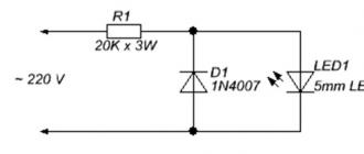
The simplest power source for LEDs from a 220V network is as follows:

In the figure shown, the resistor provides a drop in the excess voltage of the supply network, and a diode connected in parallel protects the LED element from voltage pulses of reverse polarity.
As can be seen from the figure, which can be verified by calculations, a high-power damping resistor is required, which releases a lot of heat during operation.
Below is a diagram where a quenching capacitor is used instead of a resistor.

Using a capacitor as a ballast allows you to get rid of a powerful resistor and increase the efficiency of the circuit. Resistor R1 limits the current at the moment the circuit is turned on, R2 serves to quickly discharge the capacitor at the moment it is turned off. R3 additionally limits the current through the LED group.
Capacitor C1 serves to damp excess voltage, and C2 smoothes power ripple.
The diode bridge is formed by four diodes of the 1N4007 type, which can be removed from an unusable energy-saving lamp.
The calculation of the circuit was made for HL-654H245WC LEDs with an operating current of 20mA. The use of similar elements with the same current is not excluded.
As in the previous circuit, current stabilization is not provided here. To exclude the failure of the LEDs, in the ballast circuit for LED lamps, the capacitance of the capacitor C1 and the resistance of the resistor R3 are selected with a margin so that at the maximum input voltage and increased temperature of the LEDs, the current through them does not exceed the permissible values. In normal mode, the current through the diodes is slightly less than the nominal, but this practically does not affect the brightness of the lamp.
The disadvantage of such a scheme is that the use of more powerful LEDs will require an increase in the capacity of the quenching capacitor, which has large dimensions.
The LED strip is powered from the energy-saving lamp board in the same way. It is important that the current of the LED strip matches the LED line, that is, 20mA.
We use an energy-saving lamp driver
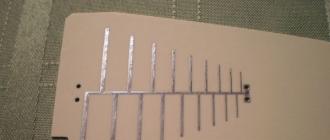
The circuit is more reliable when a driver from an energy-saving lamp is used with minimal alterations. As an example, the figure shows a rework of a 20W energy-saving lamp to power a powerful LED with a consumption current of 0.9A.
 Redesigning an LED lamp to power LEDs
 The rework of the electronic ballast for LED lamps in this example is minimal. Most of the elements in the circuit are left from the old lamp driver. The L3 choke has undergone changes and a rectifier bridge has been added. In the old circuit, a fluorescent lamp was connected between the right terminal of the capacitor C10 and the cathode of the diode D5.
The capacitor and diode are now directly connected and the choke is used as a transformer.
The alteration of the choke consists in winding the secondary winding, from which the voltage will be removed to power the LED.
Without disassembling the choke, you need to wind 20 turns of enameled wire with a diameter of 0.4 mm on it. When turned on, the open circuit voltage of the newly made winding should be about 9.5-9.7V. After connecting the bridge and the LED, the ammeter included in the power supply break of the LED element should show about 830-850mA. Greater or lesser value requires correction of the number of turns of the transformer.
Diodes 1N4007 or similar, can be used from another faulty lamp. Diodes in housekeepers are used with a large margin of current and voltage, therefore they fail extremely rarely.
All the above schemes of LED drivers from an energy-saving lamp, although they provide low-voltage power, have a galvanic connection to the AC mains, therefore, when working on debugging, you need to take precautions.
It is best and safest to use a separating transformer with the same primary and secondary windings when operating. Having the same 220V at the output, the transformer will provide reliable galvanic isolation of the primary and secondary circuits.
Is it possible to make an LED lamp (LED) operating from a voltage of 220 volts with your own hands from start to finish? It turns out you can. Our tips and instructions will help you with this fun activity.
Benefits of LED bulbs
LED lighting in the home is not just modern, but also stylish and bright. Conservative fans of incandescent lamps remain weak "Ilyich's bulbs" - the Federal Law "On Energy Saving", adopted in 2009, from January 1, 2011, prohibits the production, import and sale of incandescent lamps with a capacity of more than 100 watts. Advanced users have long since switched to compact fluorescent lamps (CFLs). But LEDs bypass all of their predecessors:
- the power consumption of an LED lamp is 10 times less than that of a corresponding incandescent lamp, and almost 35% less than that of a CFL;
- the luminous intensity of the LED lamp is 8 and 36% higher, respectively;
- the achievement of the full power of the luminous flux occurs instantly, in contrast to CFLs, which take about 2 minutes;
- the cost - subject to the manufacture of the lamp independently - tends to zero;
- LED lamps are environmentally friendly because they do not contain mercury;
- the service life of LEDs is measured in tens of thousands of hours. Therefore, LED lamps are practically eternal.
Dry numbers confirm: LED is the future.
Modern factory LED lamp design
The LED here was originally assembled from many crystals. Therefore, in order to assemble such a lamp, you do not need to solder numerous contacts, you only need to connect one pair.

The LED lamp consists of a base, a driver, a heat sink, the LED itself and a diffuser.
LED types
LED is a semiconductor multilayer crystal with an electron-hole junction. Passing a direct current through it, we receive light radiation. The LED also differs from a conventional diode in that, if connected incorrectly, it immediately burns out, since it has a low breakdown voltage (several volts). If the LED burns out, it must be completely replaced; repair is impossible.
There are four main types of LEDs:

A homemade and properly assembled LED lamp will serve for many years, while it can be repaired.
Before you start assembling yourself, you need to choose a power supply method for our future lamp. There are many options: from a battery to a 220 volt alternating current network - through a transformer or directly.
The easiest way is to assemble a 12-volt LED from a burnt-out "halogen". But it will require a fairly massive external power supply. A lamp with a conventional base, designed for a voltage of 220 volts, fits any cartridge in the house.
Therefore, in our guide, we will not consider the creation of a 12-volt LED light source, but show a couple of options for designing a 220-volt lamp.
Since we do not know the level of your electrical training, we cannot guarantee that you will get a properly working device at the output. In addition, you will be working with life-threatening voltages, and if anything is done inaccurately and incorrectly, damage and damage may occur, for which we will not be held responsible. Therefore, be careful and attentive. And you will succeed.
Drivers for LED lamps
The brightness of the LEDs directly depends on the strength of the current passing through them. For stable operation, they need a constant voltage source and a stabilized current that does not exceed the maximum permissible value for them.
Resistors - current limiters - can be dispensed with only for low-power LEDs. You can simplify the simple calculation of the number and characteristics of resistors by finding an LED calculator on the network, in which not only data is output, but also a ready-made electrical diagram of the structure is created.
To power the lamp from the mains, you must use a special driver that converts the input alternating voltage into operating voltage for LEDs. The simplest drivers consist of a minimal number of parts: an input capacitor, a few resistors, and a diode bridge.

In the circuit of the simplest driver, through a limiting capacitor, the supply voltage is supplied to the rectifier bridge, and then to the lamp
Powerful LEDs are connected through electronic drivers that control and stabilize the current and have a high efficiency (90-95%). They provide a stable current even with sudden changes in the supply voltage in the network. Resistors cannot do this.
Consider the simplest and most commonly used drivers for LED lamps:
- the linear driver is quite simple and is used for low (up to 100 mA) operating currents or in cases where the source voltage is equal to the voltage drop across the LED;
- the impulse step-down driver is more complicated. It permits powering high-power LEDs with a source of much higher voltage than is necessary for their operation. Disadvantages: large size and electromagnetic interference generated by the choke;
- The pulse boost driver is used when the operating voltage of the LED is greater than the voltage received from the power supply. The disadvantages are the same as in the previous driver.
An electronic driver is always built into any 220-volt LED lamp to ensure optimal operation.
Most often, several faulty LED lamps are disassembled, burned-out LEDs and driver radio components are removed, and one new structure is mounted from the whole.
But you can make an LED lamp from a regular CFL. This is quite an attractive idea. We are sure that many zealous owners still have faulty energy-saving boxes in their boxes with parts and spare parts. It's a pity to throw it away, there is nowhere to apply. Now we will tell you how to create an LED lamp from an energy-saving lamp (E27 base, 220 V) in just a couple of hours.
A defective CFL always gives us a high-quality base and housing for LEDs. In addition, it is the gas-discharge tube that usually fails, but not the electronic device for “igniting” it. We again put the existing electronics in the storeroom: it can be disassembled, and in skillful hands these parts will still serve something good.
Types of modern lamp bases
The base is a threaded system for quickly connecting and fixing the light source and the holder, supplying power to the source from the mains and ensuring the tightness of the vacuum flask. The plinth marking is deciphered as follows:
- The first letter of the marking indicates the type of base:
- B - with a pin;
- E - threaded (developed back in 1909 by Edison);
- F - with one pin;
- G - with two pins;
- H - for xenon;
- K and R - respectively with cable and recessed contact;
- P - focusing base (for spotlights and lanterns);
- S - soffit;
- T - telephone;
- W - with contact leads in the glass of the flask.
- The second letter U, A or V indicates in which lamps the base is used: in energy saving, automotive or with a tapered end.
- The numbers following the letters indicate the diameter of the base in millimeters.
The most common base since Soviet times is considered to be the E27 - a threaded base with a diameter of 27 mm for a voltage of 220 V.
Creating an E27 LED lamp from an energy-saving one using a ready-made driver
To make an LED lamp ourselves, we need:
- Failed CFL lamp.
- Pliers.
- Soldering iron.
- Solder.
- Cardboard.
- Head on shoulders.
- Skillful hands.
We will remake it under the LED faulty CFL of the Cosmos brand.

"Cosmos" is one of the most popular brands of modern energy-saving lamps, so many zealous owners will certainly have several faulty copies of it.
Step-by-step instructions for making an LED lamp
- We find a faulty energy-saving lamp, which has been with us for a long time "just in case." Our lamp has a power of 20 watts. So far, the main component of interest to us is the base.
- We carefully disassemble the old lamp and remove everything from it, except for the base and the wires coming from it, with which we will then solder the finished driver. The lamp is assembled using latches protruding above the body. You need to make out them and hook them with something. Sometimes the base is attached to the body more difficult - by punching dotted indentations around the circumference. Here you have to drill out the punching points or carefully saw them off with a hacksaw. One supply wire is soldered to the central contact of the base, the other to the thread. Both are very short. The tubes can burst during these manipulations, so you need to proceed with caution.
- We clean the base and degrease it with acetone or alcohol. Increased attention should be paid to the hole, which is also thoroughly cleaned of excess solder. This is necessary for further soldering in the base.

A trigger board for a gas discharge tube built into a fluorescent lamp will not work for us to create an LED device.
- The cap of the base has six holes for the gas discharge tubes. We use these holes for our LEDs. Place a circle of the same diameter from a suitable piece of plastic cut out with nail scissors under the upper part. Thick cardboard will also work. It will fix the LED contacts.

On the reverse side, the base has six round holes in which we will install the LEDs.
- We have HK6 multichip LEDs (voltage 3.3V, wattage 0.33W, current 100-120mA). Each diode is assembled from six crystals (connected in parallel), so it shines brightly, although it is not called powerful. Considering the power of these LEDs, we connect them three in parallel.

Each LED shines quite brightly on its own, so six in the lamp will provide good luminous intensity.
- We connect both chains in series.

Two chains of three parallel-connected LEDs, each connected in series
- A simple off-the-shelf driver can be taken from a broken LED lamp. Now, to connect six white 1-watt LEDs, we use such a 220-volt driver, for example, RLD2-1.

Driver connects to LEDs in parallel
- We insert the driver into the base. Another cut out circle of plastic or cardboard is placed between the board and the driver to avoid short circuits between the LED contacts and the driver parts. The lamp does not heat up, so any gasket is suitable.

A positive difference between Chinese socles and Russian ones: they are soldered much better
- We collect our lamp and check if it works.

Having assembled the lamp, you need to connect it to a voltage source and make sure that it is on
As a result, we get a pretty nice design.

Six LEDs inserted into the sockets create a powerful and uniform light source
We have created a light source with a luminous intensity of approximately 150-200 lumens and an output of approximately 3 watts, similar to a 30-watt incandescent lamp. But due to the fact that our lamp has a white glow color, it visually looks brighter. The area of the room illuminated by it can be increased by bending the LED leads. In addition, we got a wonderful bonus: you don't even have to turn off a three-watt lamp - the meter practically does not "see" it.
Creating an LED lamp using a homemade driver
It is much more interesting not to use a ready-made driver, but to make it yourself. Of course, if you are good at a soldering iron and have basic reading skills for electrical circuits.
We'll look at etching the board after hand-drawing the circuit on it. And, of course, everyone will be interested in tinkering with chemical reactions using available chemicals. As in childhood.
We will need:
- A piece of fiberglass foil on both sides with copper.
- Elements of our future lamp according to the generated circuit: resistors, capacitor, LEDs.
- Drill or mini drill for drilling fiberglass.
- Pliers.
- Soldering iron.
- Solder and rosin.
- Nail polish or clerical pencil.
- Table salt, copper sulfate or ferric chloride solution.
- Head on shoulders.
- Skillful hands.
- Neatness and attentiveness.
Textolite is used in cases where electrical insulating properties are needed. This is a multilayer plastic, the layers of which consist of fabric (depending on the type of fibers of the fabric layer, there are basalt-textolites, carbon-textolites and others) and a binder (polyester resin, bakelite, etc.):
- fiberglass is a fiberglass impregnated with epoxy resin. It has a high resistivity and heat resistance - from 140 to 1800 o C;
- foil-clad fiberglass is a material covered with a layer of galvanic copper foil 35-50 microns thick. It is used to make printed circuit boards. Composite thickness - from 0.5 to 3 mm, sheet area - up to 1 m 2.

For the manufacture of printed circuit boards, foil-clad fiberglass is used
Driver circuit for LED lamp
A driver for an LED lamp can be made independently, for example, relying on the simplest circuit that we examined at the beginning of the article. There you just need to add a few details:
- Resistor R3 to discharge the capacitor when the power is turned off.
- A pair of zener diodes VD2 and VD3 to bypass the capacitor if the LED circuit burns out or breaks.
If we choose the right stabilization voltage, then we can limit ourselves to one zener diode. If we put a voltage higher than 220 V, and choose a capacitor for it, then we will do without additional details at all. But the driver will be larger in size, and the board may not fit in the base.

This circuit allows you to make a driver for a 20 LED lamp.
We created this circuit to make a 20 LED lamp. If there are more or less of them, you need to choose a different capacity of the capacitor C1 so that a current of 20 mA still flows through the LEDs.
The driver will lower the line voltage and try to smooth out power surges. Through a resistor and a current-limiting capacitor, the mains voltage is supplied to the bridge rectifier on diodes. Through another resistor, a constant voltage is applied to the LED block, and they begin to shine. The ripple of this rectified voltage is smoothed out by a capacitor, and when the lamp is disconnected from the network, the first capacitor is discharged by another resistor.
It will be more convenient if the driver structure is mounted using a printed circuit board, rather than a lump in the air of wires and parts. You can make the board yourself.
Step-by-step instructions for making an LED lamp with a homemade driver
- Using a computer program, we generate our own pattern for etching the board according to the conceived driver design. The free Sprint Layout computer program is very convenient and popular among radio amateurs, which allows you to independently design printed circuit boards of low complexity and get an image of their wiring. There is another excellent domestic program - DipTrace, which draws not only boards, but also schematic diagrams.

Sprint Layout, a freeware computer program, generates a detailed etching diagram for the driver board
- We cut out a circle with a diameter of 3 cm from fiberglass. This will be our board.
- Choosing a way to transfer the circuit to the board. All methods are terribly interesting. Can:
- draw a diagram directly on a piece of fiberglass with a stationery correcting pencil or a special marker for printed circuit boards, which is sold in a radio parts store. There is a subtlety here: only this marker allows you to draw tracks less than or equal to 1 mm. In other cases, the width of the track, no matter how hard you try, will not be less than 2 mm. And the copper pads for soldering will come out sloppy. Therefore, after drawing the drawing, you need to correct it with a razor or scalpel;
- print the diagram on an inkjet printer on photo paper and steam the printout with an iron to fiberglass. The elements of the circuit will be covered with paint;
- draw a diagram with nail polish, which is definitely in any house where a woman lives. This is the easiest way, and we will use it. Diligently and neatly draw the tracks on the board with a brush from the bottle. We are waiting for the varnish to dry well.
- We dilute the solution: stir 1 tablespoon of copper sulfate and 2 tablespoons of sodium chloride in boiling water. Copper sulfate is used in agriculture, so it can be bought at gardening and hardware stores.
- We put the board in the solution for half an hour. As a result, only the copper tracks will remain, which we protected with varnish, the rest of the copper will disappear during the reaction.
- Remove the remaining varnish from the fiberglass with acetone. Immediately, you need to tin (cover with solder with a soldering iron) the edges of the board and the contact points so that the copper does not rapidly oxidize.

The contact points are soldered with a layer of solder mixed with rosin to protect the copper tracks from oxidation
- According to the diagram, we make holes with a drill.
- We solder the LEDs on the board and all the details of the homemade driver from the side of the printed tracks.
- We install the board in the lamp body.

After all the operations carried out, you should get an LED lamp equivalent to a 100-watt incandescent lamp.
Safety notes
- Although assembling an LED lamp yourself is not a very difficult process, you should not even start it if you do not have at least some basic electrical knowledge. Otherwise, the lamp you assembled with an internal short circuit can harm the entire electrical network of your home, including expensive electrical appliances. The specificity of LED technology is that if some elements of its circuit are connected incorrectly, then even an explosion is possible. So you have to be extremely careful.
- Luminaires are typically used at 220 VAC. But constructions designed for a voltage of 12 V cannot be connected to a regular network, and you should always remember this.
- In the process of making a homemade LED lamp, the components of the luminaire often cannot be immediately completely isolated from the 220 V supply network. Therefore, you can be seriously electrocuted. Even if the structure is connected to the network via a power supply, it is quite possible that it has a simple circuit without a transformer and galvanic isolation. Therefore, the structure should not be touched with hands until the capacitors are discharged.
- If the lamp does not work, then in most cases the poor-quality soldering of the parts is to blame. You were inattentive or hastily acted with a soldering iron. But don't be discouraged. Try further!
Video: learning to solder
It's a strange thing: in our age, when there is absolutely everything in stores, as a rule, inexpensive and very diverse, after twenty years of euphoria, people increasingly return to doing household things with their own hands. Handicrafts, carpentry and locksmith skills flourished unthinkably. And simple applied electrical engineering is confidently returning to this series.
A driver for an LED from an energy-saving lamp can be easily made in an hour, if desired.
If you have an old energy-saving lamp lying around, and the electronic ballast in it is a working one, then it is quite easy to make a driver for powering LEDs from it with your own hands. You have a question, but how to check the performance of the ballast? When disassembling the lamp, you need the lamp itself using a multimeter, and if at least one of them is burnt, then there is a very high probability that the ballast is in working order, and if both spirals are intact, then there is probably a malfunction in the ballast parts and it must be eliminated.
If everything is lying around in a disassembled state, then you just need to very carefully inspect all the parts of the ballast and the tracks of the printed circuit board for damage. Do not pay attention to the fact that the parts are darkened, they just work in very harsh temperature conditions. If everything is in order, then you can start assembling the driver for the LEDs. It makes no sense to check all the details of the ballast, since you will spend a lot of time on desoldering and checking the details. It will be much faster to assemble a circuit for powering LEDs from an energy-saving lamp and use it to check the performance of the ballast.
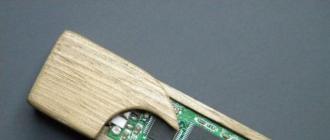
You need to start by soldering the jumpers from the wires, as in the photo and unsoldering the choke. An additional winding of copper wire must be wound on the choke.

After you have removed the choke, you need to disassemble it (disconnect the magnetic circuit) in order to easily wind the wire. First of all, carefully remove the adhesive tape from the surface of the magnetic circuit and debug it to the side, since we still need it for reassembly. We carefully try to separate the halves of the magnetic circuit with our hands (it is very fragile and breaks easily, so do not make much effort). If it does not work, then we inspect all surfaces and, if there are varnish drips that glued the magnetic circuit to the coil, then we cut and remove them with a simple clerical knife. Didn't disconnect? No problem. Then we heat the magnetic circuit at the joints with a soldering iron, a construction hair dryer or a simple lighter (just be careful, do not damage the wound wire). When heated, the varnish softens and it will be easier to disconnect the magnetic circuit. It will definitely work out.

Next, a layer of electrical insulation must be laid on the coil. The wire that is wound on the coil operates under mains voltage and, if you do not isolate it from the future winding, there is a high probability that the mains voltage will penetrate into the LED power circuit, which is a threat to your life. Insulation can be taken from old chokes, transformers, inductors, as well as a wire for winding an additional winding. You can even use paper.
![]()
We wind additional winding. The diameter of the winding wire must be selected based on the number of turns required to obtain the required voltage and a free window in the magnetic circuit. The diameter of the wire is needed as large as possible (which will fit). The thicker the wire, the more power you can get. I have LED assemblies of 24-36 volts at a current of 280-300 milliamps and I wound 30 turns of wire with a diameter of 0.35. It got in with difficulty with tight winding, and the voltage turned out to be 28 volts. It turns out about 1 volt per turn.

We assemble the choke and solder it into place. To power the LEDs, you need a constant current, but we get a pulsed one. So you need a rectifier and if you don't want to assemble it, then you can take a ready-made one, for example, from an old power supply, like mine. I draw your attention to the fact that the resulting power supply without load, in this case the LED, cannot be turned on, it will burn out.

The circuit is assembled and it remains only to test it.

When measuring the LED current, it turned out to be 290 milliamps at a voltage of 26 volts. Ideally. But the transistors in the ballast are heated. Of course, it's not scary (they are used to this), but it is better to replace them with more powerful ones or put them on radiators if the LED will work in a long-term mode. I hope now you can make a power supply yourself from energy-saving lamps for an LED. The resulting device can be used to convert old lamps into LED lamps, if everything is done carefully. I deliberately did everything roughly for clarity and speed of execution.
Good luck to you.
With the development of the latest technology, a variety of lighting products have appeared on the shelves of specialty stores, each with its own individual characteristics of brightness, economy and eye comfort.
Making LED lamp from energy-saving without soldering
For many years, manufacturers of LED lamps have tried to design a device that is similar in properties to a conventional incandescent lamp, plus all the low power consumption, low heat generation and impact on others. As a result, light bulbs were presented to consumers.
Experts advise giving preference to the latest models, explaining the choice with a number of obvious advantages. The task becomes more complicated for those who want to know how to convert an energy-saving device into an LED one with their own hands.
The main differences
The LED lamp, one way or another, provides the room with brighter illumination. With a voltage of 13 W, it gives out 1000 lumens, energy-saving - only 800 lumens.
With regard to heat transfer, it is determined by the indicators of maintaining the optimum temperature in the building, keeping household appliances and furniture in good condition. And here, too, the LED product is in the lead, having a heat transfer of 30.5 degrees with a heat transfer of an energy-saving device of 81.7 degrees.

The last product is designed for 8000 hours of active work, while the first one has a record lifetime of up to 50,000 hours. Moreover, the LED lamp does not lose its original lighting shade and brightness over time, which cannot be said about energy-saving.
The laurels of primacy go to LED sources and in the process of disposal, they can be thrown into the trash can. , thrown into a landfill, pollutes the environment (air and groundwater) with toxic mercury vapors, resulting in severe poisoning of people, animals and fish. That is why it must take place in accordance with certain rules.

Despite the pros and cons, LEDs are interchangeable - manufacturers have worried about the appropriate size for any of the lamps, and the sockets for them.
The two competing counterparts have in common a fairly high-quality color flux, which provides a high level of comfort for the human retina.
How to make an LED lamp
Necessary materials
In order to convert an energy-saving light bulb into an LED light bulb with your own hands, you must have the following list of materials with you:
- A burnt out, out of order lamp.
- A small piece of fiberglass for connecting parts together. If you have other ideas (besides soldering), you can use your own to solve the question of how to mount the LEDs.
- A set of radio elements corresponding to a certain scheme, including LEDs. Experts advise you to choose ordinary parts for assembling an LED light bulb with your own hands, which are presented in a large assortment on every radio market, where their cost is significantly lower.
- A capacitor with a volume of 0.022 Mf, the voltage of which is 400 V, one resistance is designed for 1 mΩ and a pair of resistances for 200 ohms.
- LEDs are cheaper to evaporate in the required number by means of a tape.
Making a circuit
The process of creating a diagram with your own hands begins with cutting out a circle from the PCB, the diameter of which is 30 mm. Next, apply paths on the circle, nail polish does this job well. After covering one coat, set the part aside until it is completely dry.

At this time, you can do chemistry, namely, make a mass that dissolves copper with your own hands. To do this, mix copper sulfate and ordinary kitchen salt in a 1: 2 ratio. Be sure to add a small amount of warm water (but not hot!) And dip the future board into the resulting mixture. Within a day, you will notice how the copper disappeared from the textolite circle, only the part that was varnished remained.
At the final stage, soldering is performed. However, before moving on to this phase, use a special solvent and get rid of the varnish coat. Then download the available tracks.

Take a millimeter drill and make holes in the areas of fixing the elements. Finally, move on to fully soldering the circuit. If you are not a beginner in working with a soldering iron and have certain skills, to create an LED light bulb with a voltage of 220 V with your own hands, more precisely, its driver's board, it is enough to allocate 30 free minutes.
The build process is not indiscriminate. Cut the perimeter at the very end of the plastic with a sheet of metal. Take out all the internal parts, leaving only the wires coming from the base of the old lamp. Arm yourself with a soldering iron again and fix the board to these wires.
Attach the LED circuitry to the inside of the plastic. Before final gluing, turn on the lamp, if it works, use hot melt glue.
How to do without soldering
Some may not be satisfied with soldering, in this case, as an alternative, the driver for the product is replaced with a full-fledged power supply designed for fixing and operating the LED strip. It is due to the use of a whole piece of tape, and not its separate sections, that soldering and global alteration are not required.
What problems can arise? With the dimensions of the power supply. Here you will either need to redo the electrical wiring from A to Z (the lighting of the building is reduced to one branch), or each lamp or row of products should be powered by another transformer. If the house is equipped with spotlights, you can select the very first from the circuit and place a power supply in front of it, after which, instead of 220 V lamps, install homemade 12 V LED models.
How to assemble light bulbs
Do-it-yourself assembly of lighting products is carried out from plastic pipes cut into separate sections. On the sides of the pipes, an LED strip is fixed with a soldering iron, be sure to check the parallel circuit. At the end of the wire harness, place two pins that act as a base.
If the luminaires are equipped with a traditional lamp holder, the process is greatly simplified - it is enough to modernize old energy-saving devices, and there is no need to use internal boards. As in the previous time, the sample is disassembled, and all the "insides", except for the wires of the base, are removed. The cap, from which the fluorescent tubes came out, is closed with a cylinder made of plastic, on which the sections of the LED strip are fixed. These tapes are connected to the wires from the base.
Consider "+" and "-" when connecting. Plus, it is advisable to solder to the bottom component of the base. If the connection does not work, you can solve the problem by reconnecting the output of the power supply to the wires.
Conclusion
In any case, there are plenty of ways to switch to more economical lighting. The LED lamp made on the basis of energy saving will help save you money, and the process itself will be especially appreciated by those with advanced technical thinking.
Many thanks to the manufacturers of modern energy-saving lamps. The quality of their products constantly makes you wiggle your brains and pushes you to new technical solutions.
So this time we will consider the topic of converting a failed energy-saving lamp into an LED one. Today we will go the more traditional route of using the LED driver, but ... The most interesting part of the rework is the LED itself.
The other day I got my hands on several samples of the Chinese electronics industry. These LEDs are interesting in their own right, although they do not have outstanding performance. But the fact that this LED provides a circular radiation pattern takes it to a whole new level and gives us a great tool for modernizing lighting systems.

As a radiator, I used the AP888 universal aluminum profile, already known from the last article, manufactured by Yug-Service LLC. Unfortunately, I only have a scrap that is a little over 10 mm thick. There was a concern that 9 W power might not be enough for a LED. But the urge to experiment won out.
A small drawback of this profile in relation to the new LED is the central hole with a diameter of 8 mm, and the thread of the "tail" of the LED is M6.
The solution is the simplest:
- we drill a hole up to 10 mm;
- screw the bolt into the M6 nut;
- carefully, hitting the bolt head with a hammer, press the nut into the profile. The bolt is needed in order not to accidentally jam the thread in the nut.


LED 7V, power 7-9 W, 12V, 600-800 mA. As a driver, I used a widely used 700mA driver for three LEDs from the same Chinese manufacturer.
Then, as always, everything is simple. We know how to disassemble an energy-saving light bulb, the main thing is not to break the bulb. And we are preparing the whole kit for assembly.

Despite the small size of energy saving lamps, they contain many electronic components. By its design, it is an ordinary tubular fluorescent lamp with a miniature bulb, but only coiled into a spiral or other spatial compact line. It is therefore called a compact fluorescent lamp (CFL).
And it is characterized by all the same problems and malfunctions as for large tubular bulbs. But the electronic ballast of a light bulb, which has ceased to shine, most likely due to a burnt-out spiral, usually retains its operability. Therefore, it can be used for any purpose as a switching power supply (in abbreviated form as UPS), but with preliminary refinement. This will be discussed further. Our readers will learn how to make a power supply from an energy-saving lamp.
What is the Difference Between UPS and Electronic Ballast
We will immediately warn those who expect to receive a powerful power source from the CFL - it is impossible to obtain high power as a result of a simple rework of the ballast. The fact is that in inductors that contain cores, the working area of magnetization is strictly limited by the design and properties of the magnetizing voltage. Therefore, the pulses of this voltage generated by the transistors are precisely matched and determined by the circuit elements. But such an electronic ballast power supply is quite sufficient to power an LED strip. Moreover, a switching power supply from an energy-saving lamp corresponds to its power. And it can be up to 100 watts.
The most common CFL ballast circuit is a half-bridge (inverter) circuit. It is an autogenerator based on a TV transformer. The TV1-3 winding magnetizes the core and acts as a choke to limit the current through the EL3 lamp. Windings TV1-1 and TV1-2 provide positive feedback for the appearance of a voltage that controls transistors VT1 and VT2. The diagram in red shows the CFL flask with elements that ensure its launch.
An example of a common CFL ballast schemeAll inductors and capacitances in the circuit are selected in such a way as to obtain a precisely metered power in the lamp. The performance of the transistors is associated with its value. And since they do not have radiators, it is not recommended to strive to get significant power from the converted ballast. There is no secondary winding in the ballast transformer from which the load is supplied. This is the main difference between it and the UPS.
What is the essence of ballast reconstruction
To be able to connect the load to a separate winding, it is necessary either to wind it on the L5 inductor, or to use an additional transformer. Conversion of ballast in a UPS provides for:


For the further conversion of the electronic ballast into a power supply from an energy-saving lamp, a decision must be made regarding the transformer:
- use the existing choke by modifying it;
- or use a new transformer.
Choke transformer
Let's consider both options below. In order to use an electronic ballast choke, it must be removed from the board and then disassembled. If an W-shaped core is used in it, it contains two identical parts that are connected to each other. In this example, orange sticky tape is used for this purpose. It is carefully removed.
 Removing the tape holding the halves of the core
 The halves of the core are usually glued so that there is a gap between them. It serves to optimize the magnetization of the core, slowing down this process and limiting the rate of current rise. We take our pulse soldering iron and heat the core. We attach it to the soldering iron with the joints of the halves.

Having disassembled the core, we get access to the coil with the wound wire. It is not recommended to unwind the winding that is already on the reel. This will change the magnetization mode. If the free space between the core and the coil allows one layer of fiberglass to be wrapped to improve the insulation of the windings from each other, this should be done. And then wind ten turns of the secondary winding with a wire of suitable thickness. Since the power of our power supply will be small, a thick wire is not needed. The main thing is that it fits on the coil, and the halves of the core are put on it.

After winding the secondary winding, we assemble the core and fix the halves with adhesive tape. We assume that after testing the power supply unit, it will become clear what voltage is created by one turn. After testing, we will disassemble the transformer and add the required number of turns. Usually, the alteration is aimed at making a voltage converter with an output of 12V. This makes it possible to obtain a battery charger when using stabilization. For the same voltage, you can make a driver for LEDs from an energy-saving lamp, as well as charge a flashlight powered by a battery.
Since the transformer of our UPS, most likely, will have to be completed, it is not worth soldering it into the board. It is better to solder the wires sticking out of the board, and solder the leads of our transformer to them during testing. The ends of the terminals of the secondary winding must be cleaned of insulation and covered with solder. Then, either on a separate socket, or directly at the terminals of the wound winding, it is necessary to assemble a rectifier on high-frequency diodes according to the bridge scheme. For filtering during voltage measurement, a 1 μF 50 V capacitor is sufficient.


UPS testing
But before connecting to a 220 V network, a powerful resistor must be connected in series with our block, which was converted by hand from a lamp. This is a safety measure. If a short-circuit current flows through the switching transistors in the power supply, the resistor will limit it. In this case, a 220 V incandescent light bulb can become a very convenient resistor. In terms of power, it is enough to use a 40–100-watt lamp. In case of a short circuit in our device, the light will glow.

Next, we connect the multimeter probes to the rectifier in the DC voltage measurement mode and apply a voltage of 220 V to the electrical circuit with a light bulb and a power supply board. Strands and open live parts must be insulated beforehand. It is recommended to use a wire switch to supply voltage, and put the light bulb in a liter jar. Sometimes they burst when turned on, and the fragments scatter to the sides. Usually the tests pass without problems.
More powerful UPS with separate transformer
They allow you to determine the voltage and the required number of turns. The transformer is being finalized, the unit is tested again, and after that it can be used as a compact power supply, which is much smaller than the analogue based on a conventional 220 V steel core transformer.
To increase the power of the power source, it is necessary to use a separate transformer made in the same way from a choke. It can be removed from a higher wattage light bulb burned out completely along with the semiconductor ballast products. The basis is the same circuit, which differs in the connection of an additional transformer and some other parts shown in red lines.

The rectifier shown in the image contains fewer diodes compared to the rectifier bridge. But for its work, more turns of the secondary winding will be required. If they do not fit into the transformer, a rectifier bridge must be used. A more powerful transformer is made, for example, for halogens. Anyone who has used a conventional transformer for a lighting system with halogens knows that they are powered by a fairly large current. Therefore, the transformer is bulky.
If transistors are placed on radiators, the power of one power supply unit can be significantly increased. And in terms of weight and dimensions, even several such UPSs for working with halogen lamps will turn out to be smaller and lighter than one transformer with a steel core of equal power. Another option for using workable housekeeping ballasts could be their reconstruction for an LED lamp. Converting an energy-saving lamp into an LED design is very simple. The lamp is disconnected, and a diode bridge is connected instead.
A certain number of LEDs are connected at the output of the bridge. They can be connected in series with each other. It is important that the LED current is equal to the current in the CFL. Energy saving light bulbs can be considered a valuable mineral in the era of LED lighting. They can find use even after the end of their service life. And now the reader knows the details of this application.
In this article, you will find a detailed description of the manufacturing process of switching power supplies of different powers based on the electronic ballast of a compact fluorescent lamp.
You can make a 5 ... 20 Watt switching power supply in less than an hour. It will take several hours to make a 100-watt power supply.
Currently, Compact Fluorescent Lamps (CFLs) are widely used. To reduce the size of the ballast choke, they use a high-frequency voltage converter circuit, which can significantly reduce the size of the choke.
In the event of a failure of the electronic ballast, it can be easily repaired. But, when the bulb itself fails, the light bulb is usually thrown away.

However, the electronic ballast of such a light bulb is an almost ready-made switching power supply (PSU). The only thing that the electronic ballast circuit differs from a real pulsed power supply unit is the absence of an isolation transformer and a rectifier, if necessary.
At the same time, modern radio amateurs have great difficulty in finding power transformers to power their homemade products. Even if a transformer is found, then rewinding it requires the use of a large amount of copper wire, and the mass-dimensional parameters of products assembled on the basis of power transformers are not encouraging. But in the overwhelming majority of cases, a power transformer can be replaced with a pulsed power supply. If, for these purposes, ballast from faulty CFLs is used, then the savings will be significant, especially when it comes to transformers of 100 watts or more.
Difference between CFL circuit and pulse power supply
This is one of the most common electrical circuits for energy saving lamps. To transform the CFL circuit into a pulse power supply, it is enough to install just one jumper between points A - A 'and add a pulse transformer with a rectifier. Items that can be deleted are marked in red.

And this is an already completed circuit of a pulse power supply, assembled on the basis of CFLs using an additional pulse transformer.
For simplicity, the fluorescent lamp and a few parts have been removed and replaced with a jumper.
As you can see, the CFL circuit does not require major changes. Additional elements introduced into the scheme are marked in red.

What power supply unit can be made from CFL?
The power of the power supply unit is limited by the overall power of the pulse transformer, the maximum permissible current of the key transistors and the size of the cooling radiator, if used.
A small power supply can be built by winding the secondary winding directly onto the frame of an existing choke.

If the choke window does not allow winding the secondary winding or if you need to build a power supply unit with a power that significantly exceeds the CFL power, then you will need an additional pulse transformer.

If you need to get a power supply with a power of more than 100 watts, and you use ballast from a 20-30 watt lamp, then most likely you will have to make minor changes to the electronic ballast circuit.
In particular, it may be necessary to install more powerful VD1-VD4 diodes in the input bridge rectifier and rewind the input inductor L0 with a thicker wire. If the current gain of the transistors is insufficient, then the base current of the transistors will have to be increased by reducing the values of the resistors R5, R6. In addition, you will have to increase the power of the resistors in the base and emitter circuits.
If the generation frequency is not very high, then it may be necessary to increase the capacitance of the blocking capacitors C4, C6.
Pulse transformer for power supply

A feature of self-excited half-bridge switching power supplies is the ability to adapt to the parameters of the used transformer. And the fact that the feedback loop will not pass through our homemade transformer makes the task of calculating the transformer and setting up the unit even easier. Power supplies assembled according to these schemes forgive errors in calculations up to 150% and higher. Tested in practice.
Do not be alarmed! You can wind a pulse transformer during watching one movie or even faster if you are going to do this monotonous work with concentration.
Input filter capacity and voltage ripple

In the input filters of electronic ballasts, due to space saving, small capacitors are used, on which the magnitude of the voltage ripple with a frequency of 100 Hz depends.
To reduce the level of voltage ripple at the PSU output, you need to increase the capacitance of the input filter. It is desirable that for every watt of power supply there is one microfarad or so. An increase in the capacity C0 will entail an increase in the peak current flowing through the rectifier diodes at the moment the power supply is turned on. To limit this current, a resistor R0 is needed. But, the power of the original CFL resistor is small for such currents and should be replaced with a more powerful one.
If you need to build a compact power supply, then you can use electrolytic capacitors used in flash lamps of film "mallnits". For example, Kodak disposable cameras have miniature capacitors without identification marks, but their capacity is as much as 100µF at 350 volts.

A power supply unit with a power close to that of the original CFL can be assembled without even winding a separate transformer. If the original choke has enough free space in the magnetic circuit window, then you can wind a couple of dozen turns of wire and get, for example, a power supply for a charger or a small power amplifier.

The picture shows that one layer of insulated wire was wound over the existing winding. I used MGTF wire (fluoroplastic insulated stranded wire). However, in this way, you can get a power of only a few watts, since most of the window will be occupied by the insulation of the wire, and the cross-section of the copper itself will be small.
If more power is required, then ordinary copper varnished winding wire can be used.
Attention! The original choke winding is under mains voltage! With the revision described above, be sure to worry about reliable interwinding insulation, especially if the secondary winding is wound with an ordinary varnished winding wire. Even if the primary winding is covered with a synthetic protective film, additional paper spacer is required!

As you can see, the winding of the choke is covered with a synthetic film, although often the winding of these chokes is not protected by anything at all.

We wind two layers of electrical cardboard with a thickness of 0.05 mm or one layer with a thickness of 0.1 mm over the film. If there is no electrical cardboard, we use any paper that is suitable for the thickness.

We wind the secondary winding of the future transformer on top of the insulating gasket. The wire cross-section should be selected as large as possible. The number of turns is selected experimentally, since there will be few of them.
Thus, I was able to get power at a load of 20 watts at a transformer temperature of 60ºC, and transistors - 42ºC. To get even more power, at a reasonable temperature of the transformer, was not allowed by the too small area of the magnetic circuit window and the resulting wire cross-section.

The power supplied to the load is 20 watts.
Self-oscillation frequency without load - 26 kHz.
Self-oscillation frequency at maximum load - 32 kHz
Transformer temperature - 60 ° C
Transistor temperature - 42 ° С
To increase the power of the power supply, we had to wind the TV2 pulse transformer. In addition, I increased the capacitance of the mains voltage filter C0 to 100µF.

Since the efficiency of the power supply is not at all 100%, it was necessary to fasten some radiators to the transistors.
After all, if the efficiency of the unit is even 90%, you will still have to dissipate 10 watts of power.

I was not lucky, in my electronic ballast transistors 13003 pos. 1 of such a design were installed, which, apparently, is designed to be attached to the radiator using shaped springs. These transistors do not need spacers, since they are not equipped with a metal pad, but they also give off heat much worse. I replaced them with transistors 13007 pos. 2 with holes so that they could be screwed to the radiators with ordinary screws. In addition, 13007 have several times higher maximum permissible currents.
If you wish, you can safely screw both transistors onto one radiator. I checked it works.

Only, the housings of both transistors must be insulated from the heatsink housing, even if the heatsink is inside the housing of the electronic device.
It is convenient to fasten it with M2.5 screws, on which you must first put on insulating washers and pieces of insulating tube (cambric). It is allowed to use KPT-8 heat-conducting paste, since it does not conduct current.
Attention! The transistors are under mains voltage, so the insulating gaskets must ensure electrical safety conditions!

The dummy load resistors are immersed in water as their power is insufficient.
The power allocated to the load is 100 watts.
Self-oscillation frequency at maximum load - 90 kHz.
Self-oscillation frequency without load - 28.5 kHz.
The temperature of the transistors is 75ºC.
The radiator area of each transistor is 27 cm².
Choke temperature TV1 - 45ºC.
TV2 - 2000NM (Ø28 x Ø16 x 9mm)
Rectifier
All secondary rectifiers of a half-bridge switching power supply must be full-wave. If this condition is not met, then the magnetic conductor may enter saturation.

There are two common full-wave rectifier circuits.
1. Bridge scheme.
2. Scheme with a zero point.
The bridge circuit saves a meter of wire, but dissipates twice as much energy on the diodes.
The zero point circuit is more economical, but requires two perfectly symmetrical secondary windings. Asymmetry in the number of turns or location can lead to saturation of the magnetic circuit.
However, it is the zero-point circuits that are used when it is required to obtain large currents at a low output voltage. Then, for additional minimization of losses, instead of conventional silicon diodes, Schottky diodes are used, on which the voltage drop is two to three times less.
Example.
Rectifiers of computer power supplies are made according to the zero point scheme. With a power output of 100 watts and a voltage of 5 volts, 8 watts can dissipate even on Schottky diodes.
100/5 * 0.4 = 8 (Watt)
If we use a bridge rectifier, and even ordinary diodes, then the power dissipated on the diodes can reach 32 watts or even more.
100/5 * 0.8 * 2 = 32 (Watt).
Pay attention to this when you design the power supply, so that later you do not look for where half the power disappeared.

In low voltage rectifiers, it is better to use a zero point circuit. Moreover, with manual winding, you can simply wind the winding in two wires. In addition, high-power switching diodes are not cheap.
How to properly connect the switching power supply to the network?

To set up switching power supplies, they usually use the following connection scheme. Here the incandescent lamp is used as a ballast with a non-linear characteristic and protects the UPS from failure during abnormal situations. The power of the lamp is usually chosen close to the power of the pulsed power supply under test.
When a pulsed power supply unit is operating at idle or at a low load, the resistance of the lamp cocoa filament is low and it does not affect the operation of the unit. When, for some reason, the current of the key transistors increases, the spiral of the lamp becomes heated and its resistance increases, which leads to the limitation of the current to a safe value.

This drawing shows a diagram of a stand for testing and adjusting pulsed power supplies that meets electrical safety standards. The difference between this circuit and the previous one is that it is equipped with an isolation transformer, which provides galvanic isolation of the investigated UPS from the lighting network. The SA2 switch allows you to block the lamp when the power supply delivers more power.
An important operation when testing a PSU is a dummy load test. It is convenient to use powerful resistors such as PEV, PPB, PSB, etc. as a load. These "glass ceramic" resistors are easy to find on the radio market for their green color scheme. Red numbers are power dissipation.

It is known from experience that for some reason the power of the equivalent load is always not enough. The resistors listed above can dissipate power two to three times the nominal for a limited time. When the power supply unit is turned on for a long time to check the thermal regime, and the power of the equivalent load is insufficient, then the resistors can simply be dipped into the water.
Be careful not to burn!
Terminating resistors of this type can heat up to a temperature of several hundred degrees without any external manifestations!
That is, you will not notice any smoke or color change and you can try to touch the resistor with your fingers.
How to set up a switching power supply?
Actually, the power supply, assembled on the basis of a serviceable electronic ballast, does not require special adjustment.
It must be connected to the dummy load and make sure that the PSU is capable of delivering the rated power.
During the run under maximum load, you need to follow the dynamics of the temperature rise of the transistors and the transformer. If the transformer heats up too much, then you need to either increase the wire cross-section, or increase the overall power of the magnetic circuit, or both.
If the transistors are very hot, then you need to install them on the radiators.
If a home-wound choke from CFL is used as a pulse transformer, and its temperature exceeds 60 ... 65 ° C, then it is necessary to reduce the load power.
What is the purpose of the elements of the switching power supply circuit?

R0 - limits the peak current flowing through the rectifier diodes at the moment of switching on. In CFLs, it also often acts as a fuse.
VD1… VD4 is a bridge rectifier.
L0, C0 - power filter.
R1, C1, VD2, VD8 - converter start circuit.
The launch node works as follows. Capacitor C1 is charged from the source through resistor R1. When the voltage across the capacitor C1 reaches the breakdown voltage of the dinistor VD2, the dinistor unlocks itself and unlocks the transistor VT2, causing self-oscillations. After the onset of generation, rectangular pulses are applied to the cathode of the VD8 diode and the negative potential reliably blocks the VD2 dinistor.
R2, C11, C8 - make it easier to start the converter.
R7, R8 - improve the blocking of transistors.
R5, R6 - limit the base current of the transistors.
R3, R4 - prevent saturation of transistors and act as fuses during breakdown of transistors.
VD7, VD6 - protect transistors from reverse voltage.
TV1 is a feedback transformer.
L5 - ballast choke.
C4, C6 - blocking capacitors, on which the supply voltage is halved.
TV2 is a pulse transformer.
VD14, VD15 - pulse diodes.
C9, C10 - filter capacitors.