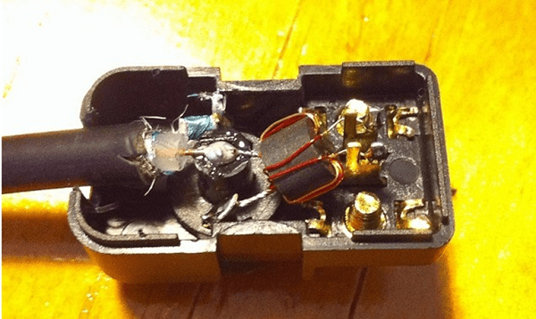
The decimeter range refers to the frequencies of television broadcasting, including digital. Some segment antennas are simple, others are complex. The purpose of the units is to receive horizontal polarization from towers. Today we will consider how the UHF antenna is made with our own hands.
Simple antenna design with a center frequency of 500 MHz
The UHF antenna, described by Radio No. 3 magazine, 1991, has been mutilated more than once, today they decided to resurrect the product so that readers can use it. A partial zigzag scheme has been completed. It comes in pairs with a converter, it is designed to receive UHF at the meter input of the TV. Those who remember Soviet technology know that there are two sockets on the back of the TV. The decimeter range was not used by the state. Broadcast regional channels.
We make a square frame from a 75-ohm cable with a side equal to a quarter of the wavelength. We take 500 MHz - we get 12.5 cm. The frame is attached with one angle down on the basis of the dielectric material:
- The top corner of the cable has been stripped. The insulation is removed, the screen is 10 mm long.
- In the lower corner, the wire is taken with a margin of a couple of centimeters. Insulation is removed from excess areas, then the screens are soldered, forming an electrical contact. The inner vein just hangs in the air.
- The antenna is fixed to the base with tinned wire with a diameter of 1 mm. Additionally enhances the contact between the screens in the lower corner.
- The rest is a square, standing on one corner, which is attached to the base.
The corners of the square are slightly rounded. Guide the fastening with wire staples in place, forming a solid structure. You can vary the length of the side of the square according to your needs. Tune the resonance to the TV broadcast frequency. If necessary, a screen is hung at a distance of 10 cm from the reverse side of the plate at a distance of 10 cm. In total, to the antenna it gives almost the side of the square, equal to 12.5 cm. The distances are chosen, determined by the wavelength.
The reflector screen is fixed with four posts, has a width of 330 mm, a height of 200 mm. The center of symmetry coincides with the building axis of the antenna. Allows reception from one direction, eliminates some of the interference. The step is useful if there is a multipath effect. At the same time, the introduction of a screen approximately doubles the gain of the antenna. The converter today looks out of place. The UHF antenna amplifier is useful if the signal is weak, the tower is far away.
It is easy to see: the design is bulky. The 75 ohm cable is designed for Soviet technology. Common TV standard. Today, devices operate powered by a 50 ohm impedance cable. Therefore, before you make a UHF antenna, you need to find it. If you can make an amplifier in addition, good! You get an active UHF antenna.
The simplest UHF antenna design
It is much easier to use coaxial cable by creating a quarter wave vibrator. We find the frequency of reception. The Moscow first multiplex uses 559.25 MHz, from here we calculate the wavelength.
This means that we will clean up by 13.4 cm. The resistance of a quarter-wave vibrator is close to 40 ohms. We take into account the fact, when agreeing, we simply stick it into the digital television receiver, having previously attached the f-connector, go to another necessary connector. We clean only the outer shell, the screen. We place the quarter-wave vibrator horizontally for better reception. The design will be assembled by schoolchildren who have found 20 rubles for a wire, a knife, a connector. The simplest do-it-yourself UHF antenna, for comparison, they ask for a lot more wooden ones for a purchased one.
Don't expect great feats, avoid being dragged to the roof. Not an outdoor UHF antenna. With a guarantee will enhance the reception of a conventional receiver. No time to tinker - try the easy way.
Antenna UHF - 855 MHz
The size of the antenna must correspond to the 69th channel of Eastern Europe, including Russia. Video is broadcast at a frequency of 855.25 MHz, sound - 861.75 MHz. As far as I can tell, the circuit is tuned to 857 MHz. For manufacturing, you will need a fair piece of wire with a wave resistance of 75 ohms. From 53 cm we make a ring with a gap, from where we will remove the signal. Please note: the screen is signal. Attach a matching U-bend of a 75 ohm cable with a half wave length of 175 mm.
It is done as follows:
- one end of the inner core of the U-bend sits on the signal wire, the cable going to the receiver, also on one side of the antenna shield;
- the second end of the inner core of the U-bend sits on the opposite end of the antenna screen.
As a result, the added line segment equalizes the resistance of the round circuit and the cable going to the receiver. In order to make an antenna for UHF digital television from the device, you need to tune it to the multiplex frequency. Let's explain the procedure in detail:
- The length of the U-bend is equal to half the wavelength of the multiplex.
- The frame diameter is equal to a quarter of the multiplex wave.
The wavelength of the multiplex can be found on the Internet, local newspapers. To accept vertical polarization, rotate the frame 90 degrees with the gap sideways. You can pick up the radio signal. The simplest outdoor UHF antennas.
All-wave antenna UHF-MV
The MV-UHF antenna provides low gain, covering channels 1-41 with a few exceptions. The design is a parallel connection of the "wave channel" of the decimeter range and the meter star vibrator.

The total length of the device is 64.7 cm. Let's start with the front edge! In the decimeter part there are 5 directors, one double reflector. If you count from the front, they have a length and distance from each other:
- Length 19.9 cm - zero distance from the front edge.
- Length 20.2 cm - distance from the first director 13.9 cm.
- Length 20.4 cm - distance from the second director 13.2 cm.
- Length 21.2 cm - distance from the third director 6.3 cm.
- Length 31.4 cm - distance from the fourth director 2.2 cm.
- Reflector length 34.9 cm - distance from the fifth director 7.7 cm.
Please note: the reflector consists of two wires, one above the other with a jumper, the middle of the UHF antenna sitting on the central axis of the TV antenna. The jumper height is 10 cm. The fifth director is an elongated oval frame, the upper turn of which is attached to the antenna axis in the center. The open part of the fifth director will serve for parallel connection of the meter part, which is mounted vertically at the rear of the antenna.
The meter part consists of 6 rays broken along the vertical axis of symmetry. One is horizontal. The beams are based on three pieces on the elements of a two-wire line 5 cm wide. When viewed from above, they are bent mirror-like forward. The angle between the beams is 120 degrees. When viewed from the front, a regular six-pointed star is obtained with an angular distance between the bars of 60 degrees. The length of each is 108 cm. To connect the structure, the center of the antenna sitting on the axis will be a two-wire line with a total length of 91.5 cm, going straight to the 5th director (lower open loop).
The line goes 11 cm further up the star. The detail goes in a semicircle, starting at the 5th director, ending at the star vertically. At a distance of 11 cm, now towards the director there are two solder points for the 75 ohm coaxial cable going to the TV. The segments from the point of the two-wire line to the star and the 5th director are chosen so that the waves of the ranges do not mix. Meter ones easily pass from the star to the cable, they don’t go to the decimeter part, on the contrary, from the 5th director the resistance is small for high frequencies, irresistible for long ones.
Television antennas DMV-MV are made of a material that provides the desired strength characteristics. The central core of the cable is placed on one wire of a two-wire line, the screen on the other. If necessary, a matching device is added. It is difficult to apply a U-elbow, the ranges are different, the author of the invention writes: no special power reflections are observed.
Other UHF antennas
The UHF log-periodic antenna is a broadband device. Catches the entire range. It resembles a wave channel in configuration, differs in that the directors are located according to a different mathematical law, which gave the name of the design to the UHF antenna. The directors are outlined by a triangle. UHF antenna Delta H111-01 is made in a similar way. Providing broadband.
Do-it-yourself antenna for UHF is made from improvised material; many metal objects can be adapted. These designs are part of all schemes, highly specialized devices work best today. Digital multiplexes do occupy one frequency. Television antennas UHF-MV become unnecessary.
We wish good luck to radio amateurs, Fortuna's help will be needed, given the absurdity of articles on the topic of design. We don't pretend to be perfect, but at least we try!
Decimeter waves long fit into the interval of 10 cm - 1 m. The feature acts as the basis for naming devices. At a frequency, electromagnetic oscillations propagate mainly in a straight line, avoiding to go around the earth's surface, being partially reflected by the troposphere. Therefore, long-distance communication of the UHF is difficult, the range does not exceed 100 km. Can a do-it-yourself decimeter antenna be assembled? Maybe actively collected by amateur engineers.
Beer cans will receive television broadcasting
UHF frequencies are located in the segment 300 MHz - 3 GHz. Many commercial, public channels fit here.
The program "Cheap and cheerful" taught Muscovites to catch Channel One. According to reports, it is transmitted in the MV band, the sound is adjacent to FM radio stations, a home-made design demonstrated by the presenter is used by the UHF.
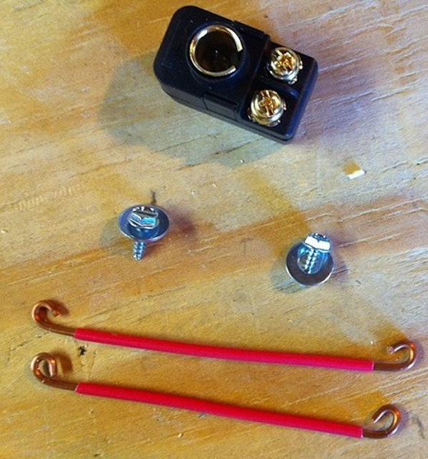
You will need two beer cans with a capacity of 0.5 liters (larger volume, lower received frequencies). You can save money by buying mineral water, juice in cans. To mount the mentioned containers, you will need a frame.
Channel One recommends using a wooden board 10 cm across, enthusiasts came up with a constructive solution. Banks are proposed to be hung on an ordinary wooden hanger. An indoor decimeter antenna made in this way is easily placed on a window handle, wall nail.
In addition to two beer cans, you will need:
- A pair of sharp self-tapping screws (screws) with a diameter of 2-3 mm, a screwdriver.
- A piece of coaxial cable from the location of the antenna to the TV.
- One standard socket connector.
- A roll of adhesive tape, insulating tape.
- A soldering iron, rosin, solder, a pair of terminals for the screws indicated in paragraph 1 will come in handy.
You should start with the termination of the connector, the terminals in the wire. The first will be located on the side of the TV, the second - from the opposite end (core, screen). Both terminals must be separated by 12 cm.
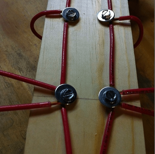
The design of the antenna avoids complications: the cans are fixed with a horizontal crossbar with their necks towards each other at a distance of 75 mm from each other. It is necessary to start the assembly by attaching the terminals to the necks with screws. There is no need to tighten it to failure, the wires should be pressed tightly against the banks.
Parallel to each other, the containers are fixed with adhesive tape on a hanger. Homemade decimeter antenna is ready. Having hung a hanger in the place of the best reception - first you need to find one - they cover it with a curtain, clothes. According to eyewitnesses, the design works, equipped with cans of a more modest displacement. You can actively experiment by changing the distance between the containers, visually evaluating the image quality.
Standard TV wire ring
The design does not require anything other than a coaxial cable with a resistance of 75 ohms (PK 75). An even ring is bent from a segment 530 mm long, reinforced with plywood, plexiglass. High input impedance will not allow you to create a direct connection to the TV, a special matching device is used - U-elbow.

A piece of cable 175 mm long is bent into a U shape. The ends are aligned with the edge of the wire going to the TV on both sides. The design is fastened with adhesive tape, any other suitable material. Three screens are soldered to each other. The cores of the U-bend are connected to the screen of the curved ring on both sides, the central wire of the television cable - on one side.
It turns out a passive antenna of the decimeter range. For outdoor use, coat the cable with compound, resin, enclose the product with a strong, impermeable plastic case.
Rings Wi-Fi, television
Two aluminum contours
"Cheburashki" firmly caught non-existence, it turned out - not completely. Many have seen a flat aluminum plate equipped with huge rings on the sides, how to make a do-it-yourself decimeter antenna? You will need two flat aluminum rings with an outer diameter of 100 mm, an inner diameter of 38 mm. Each is cut through with a slit 5 mm wide.
It turns out that two circuits will avoid the use of a transformer. A fiberglass strip, a piece of a solid board will serve as a frame. Both rings are fastened with a distance between centers of 103 mm towards the slots. The upper and lower edges of the slots are connected in pairs. The screen, the core of the coaxial cable going to the TV, is connected to the resulting pairs.
The antenna decorates the balcony, room, roof. The length of the coaxial cable to the TV is shorter, the reception is more confident.
The scheme is formed by circular vibrators. With horizontal polarization, the phase difference wave between symmetrical rings located one above the other does not occur, the cable removes the received radiation from the isthmus.
The resonant frequency of the product is 802 MHz, allowing the use of 900 MHz Wi-Fi networks, watching television channels 38 - 64. The decimeter range antenna is in perfect agreement with the RK-75 coaxial cable, showing a gain of 15 dB.
The structure is located vertically, the slots should be one above the other, respectively, the polarization of the received signal is horizontal.
Two contours of getinaks
Radio amateurs may find it attractive to use a different method of manufacturing the described design: the required figures are cut out on the board of a getinaks, textolite with one-sided foiling. Between the rings, according to the described scheme, it is necessary to leave a contact bridge with an outer width of 20 mm, a 5 mm slot inside. Two mirror holes are drilled under the coaxial cable.

The method is convenient: four mounting grooves cut into the getinax by the edge of the sheet will allow you to firmly fix the product. Use:
- wall;
- frame;
- roof.
The design is easily transposed to high, low frequencies by changing the geometric dimensions of the circles. It is easier to choose the optimal input impedance empirically (trying practical dimensions).
Sealing is carried out with plexiglass plates, the size of which is equal to that of getinaks. The perimeter of the gap is sealed with liquid nails.
An interesting feature of the type of antennas is the possibility of creating a phased array. Two identical structures are mounted vertically above each other, separated by a verified distance (the described example is 406 mm between the centers of eights). To create a single grid, a summing device is used, formed by two taps 325 mm long, fastened in the middle. The coaxial cable is soldered to the junction.
One circuit with a transformer
Now that it is clear how to make a decimeter antenna, consider the transformer mentioned above, which performs galvanic isolation of the antenna and TV circuits. The basis is the construction described above. The circuit is one, both ends are connected to the primary winding of a miniature transformer, and the coaxial cable of the TV is soldered to the secondary.
The core, formed by several turns of wire, plays the role of a matching device. For the manufacture of a hinged element, it is necessary to take an annular core with an outer diameter below 10 mm, a thickness of 2-3 mm. With a wire with a diameter of 0.2 - 0.25 mm, two windings are wound side by side, each with several turns.
The design is not inferior in efficiency to the dual-circuit models described above. Polarization - horizontal (slot should be vertical).

Digital television
Decimeter antennas for digital television are relatively easy to manufacture. You will need a wooden square with a diagonal of 200 mm, or a similar object made of plexiglass, a hefty piece of an ordinary RK-75 cable.
The option under consideration is part of a zigzag antenna, it perfectly serves the reception range of digital channels, regardless of the presence of direct line of sight to the tower. To improve performance, you should get an amplifier.
The tip of the wire is stripped 20 mm. Then a square with a diagonal of 175 mm is bent out of the cable. The end is bent outward by 45 degrees, the beginning is bent down with a stripping of a section of 20 mm, tightly wound to the end. Provides reliable screen contact. The end of the vein hangs in the air.
At the corner opposite to the beginning, the protective layer is cut off, the screen in a section of 20 mm will be the top of the antenna. The cable square is fixed symmetrically around the perimeter of the wooden sheet. In the area where the screens are connected - where the beginning and end are wound to each other - copper staples made of thick wire are used for fastening to improve electrical contact.
This is how a do-it-yourself decimeter antenna is made. For outdoor use, it must be protected by a plastic case against the effects of the external environment, or securely hidden by an opening in the attic window. Through metal, tiles, slate, the signal rarely passes. If the roof is made of PVC, plastic, fabric, similar materials, it is permissible to place the product in the attic.
To block the multipath effect, a reflector in the form of a piece of wood is used. Fastened with ebonite racks coaxially to the antenna.
The considered designs are designed to receive waves with linear polarization. It may be necessary to use helical antennas.
The article is devoted to an antenna suitable for various conditions for receiving a television signal: city, open space, long-range reception. The design of the antenna has proven itself well when receiving an analog television signal for three years. Excellent results are obtained when receiving digital TV broadcasts.
The quality of television reception depends on many factors. In the conditions of the city, the interaction of the main wave of the television signal and the reflected waves is negligible. With direct visibility between the receiving antenna and the transmitting antenna, the main wave and the waves reflected from the ground, squares, streets, roofs of buildings come to the receiving point. For radio waves, a large modern city is, figuratively speaking, a heap of “mirrors” and “screens”, which are bridges, factory pipes, high-voltage lines. High-rise buildings, like a passive repeater, re-radiate waves from the transmitting antenna. The nature of the propagation of radio waves is very complex, even near the transmitter. In the radio shadow of obstacles, a weakened useful signal is received, reflected signals, noise and interference become more noticeable. In wet walls of houses, in wet trees, the signal is weakened more strongly. The maximum attenuation of the signal received by an antenna located in the radio shade of trees occurs in summer. The addition and subtraction of the main and reflected radio waves leads to the amplification of some television signals and the attenuation of others.
Loop antennas perform well under these conditions due to side and reverse reception attenuation, they are less affected by electrical noise and, in particular, ignition noise from internal combustion engines.
For long-range television reception, the most stable image is provided by loop antennas, one of which is described in this article.
Antenna parameters
Frequency range of received signals, MHz……530 - 780
Main received TV channel ….38
The range of received television channels ... 30 - 57
Polarization of received signals………horizontal
From a wide variety of loop antennas for the UHF range, a "triple square" antenna is often made. What if the gain of the triple square is not enough, and other antenna designs are not suitable for the range of television channels of interest? At the same time, there is absolutely no place to get a sufficient number of aluminum tubes of the required diameter and specific fasteners, there is no way to assemble and install an antenna, the dimensions of which are measured in meters. Can an antenna amplifier be used that will amplify the main wave of the TV signal along with the reflected waves received by the antenna? The solution to this problem was the combination of four triple squares into an antenna system - a phased array. The antenna gain far exceeds one triple square, and the dimensions are quite acceptable. The dimensions of the construction of one of the four triple squares are shown in the figure.
For the manufacture of a triple square, galvanized steel wire with a diameter of 3 mm is required. Galvanized is a wire that has a tin coating. Such wire is easier to solder and does not rust in the open air. It takes 2 meters of wire to make one triple square. The piece of wire must not have sharp bends, dents, scratches, rust or other defects. Before manufacturing the antenna, the wire blank is thoroughly wiped with a solvent. The wire is bent according to a pattern showing the construction of a triple square. The wire joints at the top of the squares are soldered. The sections of the wire at the joints are covered with a flux prepared from hydrochloric acid by etching with zinc. With a soldering iron with a power of forty watts, and preferably sixty watts, the sections are covered with fusible solder, as far as the power of the soldering iron allows. Then the joints are pulled together with one or two turns of tinned copper wire with a diameter of 0.6-1 mm and soldered again. Finally, the joints are well soldered over the gas stove burnerusing solder and rosin. The remaining rosin is removed from the resulting structure and washed off with a solvent. The solder joint should be well tinned, providing reliable contact and mechanical strength. Triple squares must not be painted or varnished.
Before combining the triple squares into a phased array, each one needs to be checked and adjusted. Checking and adjustment is carried out indoors. A television coaxial cable with a characteristic impedance of 75 ohms is connected to the triple square, as shown in the figure. The image on the TV screen when setting up the antenna in the room may be black and white with a lot of noise. Triple square adjustment is performed based on the least amount of noise on the TV screen. If one triple square does not give a color image - it does not matter, when combined into a phased array, the image quality will increase significantly. Having connected the triple square to the antenna input of the TV, it is necessary to find the point of soldering the cable to the lower vertical part of the antenna structure by moving the connection point vertically. When moving the connection, the center core of the cable and the cable screen must be connected at the same level. In some copies of the triple square, the best image on the TV screen can be obtained by soldering the cable almost at the closing horizontal section at the very bottom of the antenna, in other copies, as shown in the figure in the third copies in the middle. Each triple square has its own optimal cable connection point. After finishing the setup and checking the triple squares, it is important not to mix up the cable connection points. To obtain a good quality of the antenna, 6-8 triple squares should be made, from which four giving the best results should be selected.
Triple squares, which are elements of a phased array, are connected by a coaxial cable. The basis of the antenna design is a wooden frame. The length of the vertical cable segments connecting two triple squares is selected experimentally. It is impossible to accurately determine the length of the cable segments in advance due to differences in the parameters of different types of cable and the unpredictable properties of the triple squares made.

Two triple squares are fixed by wrapping a PVC tube on one vertical frame element, which is a wooden block. In turn, identical pieces of cable 220, 240, 260.280, 300 millimeters each are connected to the triple squares. The opposite ends of the cable segments are connected to the screen-screen and core-core and connected to the cable going to the antenna input of the TV. The length of the vertical cable segments connecting two triple squares is selected according to the best image quality. The main contributor to the tuning is the length of the cable segments compared to the distance between the triple squares. When setting up, you can reduce or increase the distance between the triple squares, but this will not give much effect, so the distances in the design drawing between the triple squares are not given. The image on the TV screen should be better than when received on one triple square.

The frame is temporarily assembled from four wooden bars fastened together with a rope. Four triple squares are installed on the frame, connected by vertical cable segments. The length of two identical horizontal cable segments connecting the vertical segments with the cable laid to the TV antenna input is specified experimentally. For the final adjustment, two identical horizontal segments with a length of 130, 150, 170 or 190 millimeters are alternately soldered.
For the final manufacture of the frame, four wooden bars 8-11 millimeters thick, 60-70 millimeters wide, 520 millimeters long and three wooden bars of the same thickness and width 490 millimeters long will be required. The ends of the bars are coated with epoxy resin and dried for five days, then the entire surface of the bars is coated with epoxy resin and dried for five days. After coating with epoxy resin, wooden bars are painted with nitro paint at least twice. Before installing triple squares and cable segments that combine triple squares into a phased array, the first part of the frame is assembled from two vertical and two horizontal bars. The contacting surfaces of the bars are coated with epoxy resin, connected with screws and dried for at least three days. After the epoxy resin dries, the two screws connecting the upper horizontal bar with the vertical bars are unscrewed. Four screws securing the central horizontal bar remain.

Triple squares are installed on a wooden frame, connected by pieces of a coaxial cable. Triple squares are attached to the frame with several turns of PVC tubing. A cable is soldered to the antenna, going to the TV of the required length.

For correct phasing of the antenna system, the center conductors and screens of the coaxial cable segments are connected to triple squares in accordance with the phasing scheme. The end of the cable connected to the antenna is enclosed in a PVC tube with a diameter of 10-12 millimeters and a length of about three meters to protect the antenna cable from the weather. The PVC tube and cable are fixed with a thread on a horizontal bar. The soldering of the screen and the central core of the cable segments are isolated from each other with electrical tape. On top of the installed triple squares and cables, two vertical bars are installed, on top of them in the center is one horizontal one. The frame parts are connected with screws with a diameter of 6 millimeters. When installing the screws, the holes left after unscrewing the screws connecting the upper horizontal bar with the vertical bars are used. Coaxial cable segments and parts of triple squares are enclosed inside a wooden structure that reliably protects the solder points from the weather.
The gaps between the bars from the sides and ends are sealed using building sealant "liquid nails".

The antenna is mounted on the mast using clamps corresponding to the diameter of the pipe. Screws pass through the holes in the horizontal bars. The antenna is fixed at two points. By loosening the clamp screws, you can precisely orient the antenna to the transmitter.

Galvanized wire, pipe clamp, epoxy, paint can be purchased at a building materials store. A coaxial television cable with a wave impedance of 75 ohms should be selected with a central conductor of copper and a double screen consisting of foil and braid of copper conductors. Best results can be obtained by using the largest diameter cable with as many strands as possible in the shield.
The distances between the elements of the phased array, the dimensions of the triple square and the length of the cable segments were chosen through numerous experiments in order to ensure the reception of the largest possible number of television channels and at the same time the smallest possible dimensions, reducing the mass of the antenna and facilitating installation. Reception on the antenna is possible through an obstacle from closely spaced trees. The antenna has a low windage. Due to the location of the cables inside the wooden sealed frame, a long service life and protection from the influence of weather factors are ensured. The quality of the received image does not depend on the time of year and time of day.
Despite the huge number of television antennas on the consumer market, which can be easily purchased at any electronics store, interest in how to make a do-it-yourself TV antenna does not disappear. Such interest can be explained by the reluctance to spend money on buying an antenna, being away from retail outlets (if you are in the outback or in the country) or the failure of the purchased one.
Antennas for a television receiver can be divided into several types.
- All Wave Antenna- the design is easy to manufacture, can be made from simple improvised materials. It picks up a digital signal quite well outside the city, where there is not much interference. When located near a broadcast tower, it can receive analog television.
- Log-periodic band antenna also easy to make. It has perfect coordination with the feeder in all ranges, without changing the parameters in it. Since this design has average technical parameters, it can be used in the country, or as an indoor antenna in the city.
- decimeter antenna. A simplified modification of the Z-antenna is often used, it works well, regardless of the signal reception conditions.
All Wave Antenna
All-wave TV signal catchers are also called frequency-independent (CNA). Their designs may be different.
From two petals
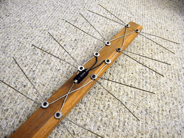
The figure shows an all-wave antenna made of two metal plates triangular shape and two wooden slats, on which copper wire is stretched in the form of a fan.
Copper wire can be taken of any diameter, it does not play a special role. The ends of the wire are fastened at a distance of 20 to 30 mm between each other. Plates with the other ends of the wire soldered together should be located at a distance of 10 mm from each other.
The metal plate can be replaced with a square piece of fiberglass, which has copper foil on one side.
Since the design of a homemade antenna has a square shape, its height will be equal to the width, and the angle between the canvases will be 90 degrees. Zero potential point marked in yellow in the figure. Soldering the cable braid in this place is not required - a tight tie will be enough.
The television signal receiver assembled in this way in the form of two petals is capable of receiving both all decimeter channels and meter ones. Moreover, it catches the signal well in all directions. But if you install the CNA in the zone of poor signal reception from the TV tower, it will only work normally with amplifier. Others can be applied as well.
In the shape of a butterfly
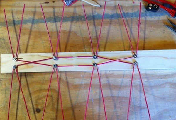
Do-it-yourself TV antenna can be made in the shape of a butterfly. To make this fairly powerful antenna yourself, you need to prepare a board or plywood with dimensions of 550 x 70 x 5 mm, a wire with a copper core section of 4 mm, and, accordingly, a PK75 cable.
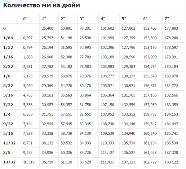
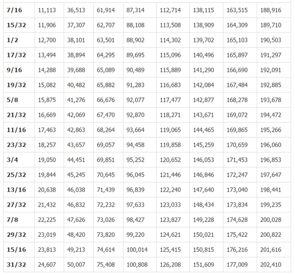
- Mark the holes on the plywood and drill them. The dimensions in the picture are in inches. Below the figure is a table for converting inches to mm.
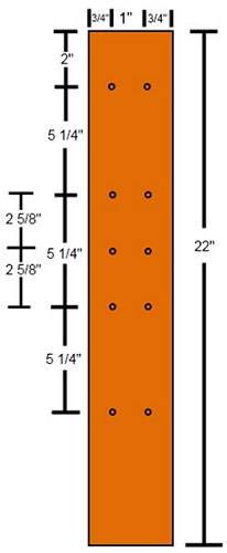
- From copper wire, it is necessary to cut 8 pieces of the same length of 37.5 cm.
- In the center of each wire, strip the insulation from the sections (2 cm each), as in the figure.

- After that, you should cut off 2 more pieces of wire, already 22 centimeters each, divide them into 3 equal parts and remove the insulation at the separation points.
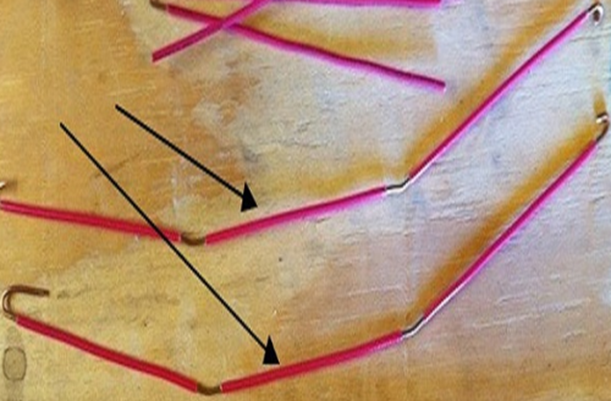
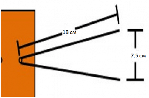
- Attach segments V-shape. You should be careful to maintain a distance of 7.5 cm between the ends of the wire. It is this that is optimal in order to receive a clear signal.
- Connect all the elements according to the figure below.
- Next, you need to purchase a socket for connecting a plug to it.
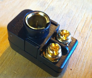
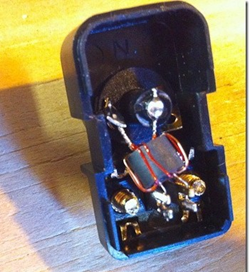
- The cable must be soldered to the coil contacts, as in the figure.
- Make 2 more pieces of wire of the required length to connect the "antennae" to the socket.
- Screw the socket onto the plank and connect all the elements.

That's all - you made an antenna for the TV with your own hands.
From beer cans
To make such an original CHNA, you will need 2 cans (0.5 l or 0.75) of beer or another drink. But before you make a television antenna, you need to consider some material requirements. Namely, it is recommended to purchase a high-quality television cable with a resistance of 1 meter 75 ohms. How right? Pay attention to the fact that the central core is strong, and the braid is double and solid.
Do not forget, the longer the cable, the stronger the signal attenuation will be, which is especially important for receiving meter waves, unlike UHF, for which the length of the wire also matters, but not so much.
It will also be necessary to prepare the usual wooden trempel, a couple of self-tapping screws, electrical tape or adhesive tape and, if possible, a soldering iron with tin.
Antenna from beer cans can receive both decimeter and meter wavelengths.
For clarity of the whole process, you can watch the video.
log-periodic antenna
A log-periodic antenna (LPA) can be used to receive radio waves in both the meter and decimeter ranges. To make such a signal receiver, you can use an aluminum tube with a diameter of 10 mm and metal rods (studs) as a stand, which can be bought at a store that sells fasteners. Ideally, instead of threaded rods, it is better to use smooth tubes or rods. A plastic U-shaped box is taken as the basis.
When the soldering is completed, the manufacture of the device can be considered complete and you can start testing your creation.
decimeter antenna
Homemade decimeter signal catchers can have a variety of shapes and designs, from the simplest to manufacture to more complex devices.
annular
The simplest design for receiving UHF can be done in a short time with your own hands from improvised materials. All you need is a coaxial cable and a piece of plywood of the right size.

Now all this needs to be collected:
- prepare a piece of coaxial cable (PK75) 530 mm long (a ring will be made from it);
- also cut another piece of cable 175 mm long - this will be a loop;
- make a ring (1), solder a loop (2) to it and a cable (3) that connects to the TV;
- fix it all on a plywood sheet and direct the TV signal receiver made towards the TV tower.
If your TV receiver is using such an antenna, try making a more complex device.
in the shape of a figure eight
A do-it-yourself home UHF antenna can be made from wire in the form of the number 8. To make such a receiver, you can use copper or aluminum wire with a diameter of 3 to 5 mm, as well as a PK75 cable. During the manufacturing process, you will also need glue gun.

Manufacturing progress.
- Using wire cutters, cut 2 pieces of wire 56 cm each.
- At the ends of each segment, make a loop, which should take 1 cm.
- Bend the wire squares and connect the loops. Solder the cable to the squares as shown. The central core is soldered to one square, and the braid to the other. The distance between the elements should be 2 cm. The entire structure can be fixed in the cap from under the 20 liter water bottle, filled with glue.

Such a UHF receiver can be placed anywhere, and it does not require an amplifier. Unless, an amplifier may be needed if the device is outdoor, and the cable length is significant. In this case, to compensate for signal loss, you will need to install it.
From a metal-plastic pipe
A do-it-yourself television antenna can also be made from an ordinary metal-plastic pipe. This will result in a device for receiving UHF with a possible range from 480 MHz to 1000 MHz. This “model” uses a pipe with a diameter of 16 mm and a cable - 5.5 m. The ring will require 55 cm of pipe, and the rack - 14 cm, which is equal to a quarter of a wavelength. This serves to better match the outer sheath of the cable and reduces high frequency currents.

The cable outlet in this design is made through a hole in the pipe. The cable braid should be attached with a clamp to the stripped part of the pipe. The central core of the cable is attached to the ring (you can use a screw with a washer and nut). Such a homemade product works well as a room antenna in apartments with reinforced concrete walls that do not transmit the television wave well. Thanks to the extended cable, you can take it out to the balcony or put it on the windowsill - the reception quality will only improve.
framed
Another design of the UHF antenna is assembled in the form of a frame. It will be made from aluminum plates(bands).

Thus, do-it-yourself antennas will help you save money on their purchase, and in some cases get out of a situation where there is a TV, but the standard antenna is out of order, or it is not there at all. Moreover, the quality of receiving homemade products is not worse than factory counterparts. If you do not want to make the device yourself, then you will need information about that in the store.
In continuation of the topic of antennas for digital television, today, dear anonymous author, we will take a closer look at a very popular antenna Yagi-Uda(or " I gu", or wave channel). The antenna is quite capricious to manufacture, as we have already said, but it is so popular with DIY antennas that we simply cannot ignore this topic. On the other hand, unlike the microwave range, in the UHF range, where digital television broadcasts, it is quite possible for a DIY-shnik to make an antenna with good gain without instrument tuning. Under the cut, two Yagi-Uda designs for DVB-T2 from available materials are presented ...
However, before we consider practical designs, an anonymous person far from antenna theory needs to clarify several important points for himself:
- First of all, Yagi-Uda is not just an antenna design, it is a very large class of antennas, including a huge number of subclasses and a myriad of practical designs. The wave channel can be both narrowband and broadband, have completely different input impedance and at the same time contain a different number of elements. Generally, other things being equal, a longer antenna with more elements has more gain.
- The Yagi-Uda calculator of the DL6WU design presented on our website calculates a narrow-band antenna of the Long-Yagi subclass with an input impedance of 200 ohms, which was specially designed for amateur VHF radio communications. Obviously, such an antenna is completely unsuitable for DVB-T2 reception.
- To receive digital television, we need a broadband Yagi-Uda, which overlaps according to the SWR criterion< 2 по возможности большую часть ДМВ диапазона, с входным сопротивлением около 300 Ом, что позволит использовать ее с широко распространенными пластинчатыми усилителями или широкополосными балунами/симметризаторами 300:75 Ом, так же как и в антенне Харченко для DVB-T2 .
- Old books on television antennas usually reprint dimensions for Yagi-Uda channel non-broadband designs. Since it is now difficult to find a region in which only one multiplex operates, such "old-fashioned, time-tested" designs are already of little use for DVB-T2 reception. Moreover, such designs as the Turkin antenna and others are not suitable.
 A huge number of practical designs can meet the selection criteria given above. Therefore, questions like “Why are there and there sizes different from yours?” will be incorrect, friends. For the same reason, there is no perfect Yagi-Uda design. Each design has its pros and cons compared to other similar ones. Common techniques for expanding the bandwidth of the wave channel are the use of a double or corner reflector instead of a single one, a double first (or several) directors, a closer location of the first director to the vibrator, complicating the design of the vibrator, the rejection of linear elements and the transition to more broadband "butterflies" . It is rather difficult to select the optimal dimensions using a computer, since the more elements an antenna has, the more complex they are structurally, the more degrees of freedom it has. However, the designs proposed below, authorship yurik82
, are optimized using N. Mladenov's script for 4NEC2 with subsequent "debugging" in the HFSS program (as well as the Kharchenko antenna). In addition, in this case, you need to understand that since the antennas are designed for almost the entire UHF range, no “calculator” is needed to calculate, let alone a “formula”, it is enough to make the antenna as close as possible to the drawing with an accuracy of no worse than ± 1 mm.
A huge number of practical designs can meet the selection criteria given above. Therefore, questions like “Why are there and there sizes different from yours?” will be incorrect, friends. For the same reason, there is no perfect Yagi-Uda design. Each design has its pros and cons compared to other similar ones. Common techniques for expanding the bandwidth of the wave channel are the use of a double or corner reflector instead of a single one, a double first (or several) directors, a closer location of the first director to the vibrator, complicating the design of the vibrator, the rejection of linear elements and the transition to more broadband "butterflies" . It is rather difficult to select the optimal dimensions using a computer, since the more elements an antenna has, the more complex they are structurally, the more degrees of freedom it has. However, the designs proposed below, authorship yurik82
, are optimized using N. Mladenov's script for 4NEC2 with subsequent "debugging" in the HFSS program (as well as the Kharchenko antenna). In addition, in this case, you need to understand that since the antennas are designed for almost the entire UHF range, no “calculator” is needed to calculate, let alone a “formula”, it is enough to make the antenna as close as possible to the drawing with an accuracy of no worse than ± 1 mm.
Plate Yagi-Uda for DVB-T2 from galvanization on a dielectric boom.
The first design is the cheapest "garage" option. It is made of galvanized strips 15 mm wide and 0.5 to 1 mm thick. The strips are placed on a dielectric arrow, for example, a wooden one, made of pine timber, treated with an antiseptic and varnish. The design consists of a loop vibrator, a double reflector and ten directors. The antenna is not able to cover the entire UHF range according to the SWR criterion< 2, поэтому предлагаются два варианта размеров. Первый рассчитан на полосу 470-690Мгц (21-48 частотные каналы), второй - 500-800МГц (25-61 частотные каналы). Вам необходимо выбрать один из вариантов в зависимости от того, на каких частотах работают мультиплексы в вашем регионе. Ниже представлен чертеж антенны, размеры сведены в таблицу.

| f MHz | d5 | d6 | d7 | d8 | d9 | d10 | r | h | Z |
| 470..590 | 408.9 | 530 | 619.3 | 748 | 924.2 | 1051.8 | 96.7 | 20.5 | 174.4 |
| 500..800 | 357.8 | 463.8 | 541.9 | 654.5 | 808.7 | 920.3 | 84.6 | 20.5 | 160.5 |
The input impedance of the antenna is 300 ohms. Gain - from 8.5 dBi in the lower part of the operating range to 14.5 dBi in the upper one. Suppression of the rear lobe of the radiation pattern is not worse than 17 dB. SWR within the operating range does not exceed two. With such an SWR, the antenna is able to work stably in conjunction with a modern low-noise antenna amplifier. In more detail, with graphs, the characteristics of the antenna can be viewed at the first link at the end of the article, and at the fourth link, a seven-element design with a bandwidth of 470..690 MHz and a gain of 8..12 dBi is presented.
Yagi-Uda for DVB-T2 from tubes on a metal boom.
The second design with a corner reflector is similar to the one shown at the beginning of the article, only with 12 directors. It is somewhat more difficult to manufacture and can be done by more advanced DIYers. The input impedance of the antenna is also 300 ohms and it also works stably in conjunction with the antenna amplifier. 
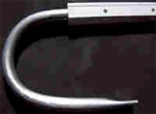
The directors and elements of the antenna reflector are made of duralumin tubes with a diameter of 6 mm; a tube with a diameter of 8 mm is used to manufacture the vibrator. Boom and corner reflector are made of duralumin profile 15x15 mm. The antenna elements are not isolated from the boom, but the boom is mounted on a metal grounded mast, which helps to protect against atmospheric static. This is the advantage of this design over the previous one. The vibrator is attached to the lower edge of the boom, the directors and reflector elements are pressed inside the boom. The axes of the directors are shifted upward relative to the axis of the boom by 3.5 mm (or 4 mm from the upper edge of the boom to the axis of the director), as a result of which they are actually located inside the boom directly along its upper edge. This is if the antenna is located as in the photo and drawing, of course it can be turned 180 ° relative to the axis of the arrow. The structural dimensions of the antenna can be seen in the following image: 
Operating range of the antenna according to the SWR criterion< 1,7 от 470 МГц до 710 МГц (21-50 частотные каналы). Усиление антенны от 9,5 dBi на нижнем участке рабочего диапазона до 14,5 dBi на верхнем. Подавление заднего лепестка диаграммы направленности не хуже 14 dB. Подавление частот метрового диапазона не хуже 19 dB, подавление FM диапазона не хуже 38 dB в сравнении с изотропным излучателем. Подробнее, с графиками, характеристики антенны смотрите по второй ссылке в конце статьи.
 For those who find it easier to attach the strips than to press in the tubes, a model of this antenna has been developed on a square metal boom 15x15 mm with elements in the form of strips 15x2 mm: https://ypylypenko.livejournal.com/91602.html Dimensions W1..W12 - lengths directors, X1..X12 - distance from the center of the vibrator to the center of the corresponding director. The constructive dimensions of the reflector and the vibrator are shown in separate images. The distance between the ends of the vibrator 24 mm can be safely changed within 16..24 mm, depending on the available
Digital TV is sweeping the country, many people are buying TVs that already support this format. And whoever has the previous generation equipment, you can buy a digital set-top box () and connect it to your old TV, which does not support. In general, the standing format allows you to watch television in digital format. BUT, many sellers, along with set-top boxes and TVs, "push" the so-called digital antennas, sometimes the price of the antenna reaches 3,000 rubles. Although you guys can do it yourself, make an antenna for digital television, and very cheaply ...
ADVICE! Guys, by the way, you can watch TV without an antenna at all via the Internet, but for this you need another prefix - read a really cool topic.
We continue the article...
To receive a digital signal, a so-called decimeter antenna is required. You can literally make it from an antenna cable. However, it must be calculated correctly. If you do not want to read the article in full, you can find the desired item in the table of contents.
What you need to make an antenna
1) We need a piece of antenna cable, about 30 cm long.

2) Antenna connectors, the so-called F-connector and male-female connector.

F - connector and "father-mother"
3) Tools: a knife, wire cutters, a calculator and a tape measure (well, or a ruler).

Payment

On the main page, we are looking for a tab - “CETV coverage map” and go to it.

CETV coverage map tab
Before us opened a map of coverage of digital television. We are looking for the nearest station for our city (I have Ulyanovsk, you fill in your city).


As you can see in my city, these are channel 56 - 754 MHz and channel 59 - 778 MHz.
Now we calculate the length of the antenna. I will not go into complex technical formulas and terms, we do not really need them. But to calculate the antenna, you need to divide 7500 by our frequencies.
THAT is: 7500/754=9.94 cm, this is for channel 56.

7500/778=9.64 cm, this is for channel 59.

Our antenna should be about 10 cm, and exactly - ((9.94 + 9.64) / 2 = 9.79 cm)
For your city, you also need to display the average length for your stations, if you have more than one in the city. In the video under the article, I calculated the antenna for Ulyanovsk, and for Kazan.
Manufacturing
1) We take a piece of antenna wire and first we attach an F-connector at the end. We simply strip the cable and screw on the connector so that the center wire is in the middle, and the screen (wires and foil were in the mount), detailed (useful).


2) Set aside a couple of centimeters from our connector (this will be a kind of indent), then measure 10 cm and cut off the unnecessary cable.

3) Now from these 10 cm, we need to remove the plastic insulator and remove the "screen" (foil and small wires). You don’t need to touch it further, leave the cable in the insulator.
4) All our antenna is ready. You can try to connect.

Connection
You need to get a good reception point in the apartment, and it's not always enough just to insert it into a TV or set-top box. I have such a place near the window, so I inserted an extension cord into the console and already inserted the antenna into the extension cord. So far, all this has not been improvised removed from me, for an example of work (therefore, the cable weighs), and the antenna itself is inserted into it.


Well, as you can see, all channels are working fine, and "first", and "Russia", and NTV, etc.

"First"


Thus, if you have 80 - 100 rubles, you can make an antenna for digital television (DVB-T2 standard) with your own hands, easily and simply.
Now video version
For those who do not show - - MANDATORY! There is a solution to the problem!
That's all, I think my article is very useful and relevant. Read our building site.
Today, terrestrial television is the most common among users. It works by capturing the radiation from the broadcaster to the receiver. Due to a number of factors, the antenna may fail, and it is not possible to install a new one at the moment.
In this case, you can make a home-made antenna for digital television, which will receive a television signal no worse than factory devices. This article will consider the manufacture of different types of antennas for digital TV with your own hands for specific conditions, for temporary and permanent use.
Receiving Antenna Types
A television antenna is a dipolar device that can emit and receive a signal in a specific frequency range.
Today, several types of devices are common for television:- VHF (MV antenna, VHF). Designed to receive on-air analog broadcasting, which occurs in the frequency range of 1 - 300 MHz.
- Decimeter wave band (UHF antenna, UHF). They receive shorter wavelengths of radiation, which transmit a signal at frequencies of 0.3 - 3 GHz.
In the UHF band today broadcasts television digital standard DVB.

- Terrestrial television (DVB-T2). It works by transmitting the signal from the broadcaster to the receiver via terrestrial repeaters. Signal emission occurs at frequencies of 314 - 898 MHz.
- Satellite TV (DVB-C2). Broadcast at ultra-high frequencies from 1 GHz.
From the operating ranges discussed above, we can conclude that for a simple digital television antenna there is a limit to the minimum and maximum wavelength that it can receive. So, before assembling the antenna with your own hands for digital television, you will need to calculate it.
Payment
Depending on the design, you can make an all-wave antenna yourself or work in a specific frequency range. There is one fundamental difference between them - all-wave devices are not capable of receiving a weak signal, especially muffled by a background of stronger radiation. Other homemade antennas do not cover all digital broadcast frequencies.

In order to properly make a working antenna for digital TV, its calculation must be approached responsibly for one more reason - in practice it is impossible to check the quality of digital signal reception.
If, at a low signal level, analog television works with interference, but shows, then there is no image in the digital and it is not clear whether the problem is in the device or in something else (cable, weak signal at the reception). In this case, development work with the antenna already on will not work.
Modern Smart TVs and receivers display the level of the signal recorded on the receiver, but most conventional digital devices do not support this function. It is impossible to make even a simple decimeter antenna without calculation, unless it is all-wave.
Calculation rules
Digital TV broadcasts from different multiplexes at different frequencies, which corresponds to different wavelengths. In order to receive a high-quality signal, the emitted wave must completely “lie down” on the active region of the receiver.
Therefore, do-it-yourself calculation of an antenna for digital television must be performed according to the following scheme:- calculate antenna DVB-T2 wavelength, emitted during the broadcast of each multiplex;
- choose the longest wave;
- calculate the half-length of the cross section of the wave, because it is projected perpendicularly to the receiver.
Below, we will consider the procedure for calculating the active area for a digital antenna with our own hands, and as an example, we take the calculation of the broadcast frequency in Moscow.
Practical example

- 1st multiplex (32 TVK, 546 MHz);
- 2nd multiplex (24 TVK, 498 MHz);
- 3rd multiplex (34 TVK, 578 MHz).
The calculation of the wavelength is carried out according to the formula ƛ = 300/F, where F is the frequency in megahertz (MHz). As a result, each multiplex sends a wave:
- ƛ1 = 300/546 = 0.55 m;
- ƛ2 = 300/498 = 0.60 m;
- ƛ3 = 300/578 = 0.52 m.
It turns out that the repeaters of the second multiplex of Moscow television emit a wave of the greatest length, which in the future will be used for calculation.
Important! For ease of calculation, the resulting value can be rounded up, but only up!
The only thing left is to calculate the length of the active region of the future receiver, which will receive the signal. Because the radiated wave has a sinusoidal shape, then its cross section will be ½ of the length, and the half-length will be ¼. The total is 0.60/4 = 0.15 m = 15 cm for digital television.
Advice! As an example, the calculation for all multiplexes is shown, but it can be simplified by calculating the value for only one channel package. The greatest length of an electromagnetic wave will always be at radiation of lower frequency.
Location and connection
When theoretical calculations were made, it remains to plan the future design for assembly with your own hands.
There are two issues with planning:- location
- connection .
- You can make a home or outdoor antenna with your own hands. The latter can be a simple unidirectional receiver for television, which is not interfered with by signal-attenuating barriers (house walls, other buildings).
Also, an outdoor digital antenna can be installed on the roof, which will significantly improve the quality of the received signal. It should be directed to the digital television repeater.
- For outdoor installation, and even more so on the roof, an extended cable is required. It causes natural signal dispersion (noisiness) and the longer its length, the weaker the signal level reaches the TV.
To make a do-it-yourself digital television antenna that will work effectively, you will need to find a compromise between these factors.
In a densely built-up area or sparsely populated areas with a large distance from the television repeater, the digital antenna will have to be taken out into the street. In other cases, the room receiver also works effectively.
Advice! There is no clear rule for choosing a placement, each case is unique. The best indicator of a reliable installation is neighboring houses. If there are a lot of street devices for receiving television, it is also to be made. In the area of super-dense buildings, you need to look at the roofs of multi-storey buildings.
A small number of receivers still do not indicate anything (sometimes, to be sure, residents install them even in conditions of good reception by room devices). Only if there are many antennas, and among them there are collective ones, installation on the roof will be required.
Manufacturing
When the calculation is completed and the type of future receiver for terrestrial television is selected, you can proceed to the main assembly work. It is worth noting that it is impossible to make a DVB-T2 digital TV antenna with your own hands, the design of which is suitable for all cases. Therefore, several types of home-made devices for specific tasks will be considered.
From beer cans

An important advantage of such an antenna for television is the rapid manufacture of improvised means. The whole process will take no more than 15 minutes. It is easy to assemble such an antenna, but for effective operation you will need a high-quality signal and the absence of obstacles. It is suitable for residents of small towns and suburban areas.
You will need the following parts and tools for assembly:- 2 beer cans;
- bolts and screws with a screwdriver;
- 2 wooden sticks;
- a piece of copper wire;
- electrical tape or tape;
- antenna plug and cable.
The device requires a T-shaped frame or in the form of a cross. It is made from wood.
After that, the main manufacturing process follows the following scheme:
- In the middle of the bottoms of the cans, make a hole for the bolts.. You can use scissors or a screw.
- Remove the insulating coating from the cable for a length of three jars + 20 cm. the outer contour is not touched.
- Place the cans parallel with their necks to each other and pull the cable through one hole to the other. At the end, it must be fixed with a self-tapping screw or bolt.
- Fasten the cable coming out of the hole and its bare area between the banks with wire. The connection point is mandatory, otherwise there will be a lot of noise in the cable and the image will not appear on the screen.
- Banks fix with one skein of adhesive tape or electrical tape to the horizontal bar of the frame.
- Attach plug to cable.
Attention! Cable bends must be handled with care! Only a solid outer circuit effectively suppresses noise in it, and if it is damaged, the transported signal will be greatly attenuated. No need to try to "save" the bare part of the cable, for this there is a margin of 20 cm.

The ethereal antenna from beer cans has already been assembled, it remains to determine the optimal distance between the banks. To do this, you need to connect the plug to the antenna and move the banks along the bar (bringing them closer and further away from each other) until a good signal is caught. In most cases, 6-7 cm is sufficient.
When the optimal location of the cans is found, they must be firmly fixed to the contour.
For outdoor use, it is recommended to wrap a self-made construction for television with polyethylene or make a special plastic frame. As a fastener, it is better to use a hook and hang the structure. If a bare cable of considerable length remains at the exit from the hole, it must be wrapped with electrical tape, leaving no more than 2 cm.
in the shape of a figure eight

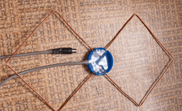
For digital TV, a self-made G8 antenna is popular, which is also called a biquadrat or Kharchenko antenna. Outwardly, its active region is represented by a double diamond-shaped square. Such a home-made design successfully works in almost any conditions, with the exception of ultra-dense buildings, because. unable to receive the reflected signal.
For the “eight”, a calculation by wavelength is required, and each side of the square must correspond to the half-length of the wave section, therefore, its perimeter is equal to the length of the wave itself. For Moscow DTV, the side and perimeter will be 15 and 60 cm, respectively.
The material for the manufacture of the antenna can be copper 2-3 mm or aluminum wire 5-6 mm. In total, you need to make two squares. From the ends of the wires, you need to cut off 2 cm and connect them together in such a way that you end up with a single structure of two squares with a common angle.
Important! The connected pairs of wire ends must be isolated from each other, otherwise the device will only be a signal emitter!
A beam can be used as a frame. The receiver can be fixed immediately without prior fixation, because. the antenna is manufactured according to the calculation and a practical experiment with the signal is not required. The cable must be soldered in the middle to one of the connecting points of the ends of the wires.
double-triple square

The antenna is manufactured in the same way as the biquad device. The general design is represented by several squares of the same parameters, located one after the other. Unlike the G8, it is not capable of receiving a good signal from a very remote television repeater.
The purpose of a double or triple square is to receive a signal in conditions of a strong radiation background. In an area of super-dense development, it often happens that a DTV tower is nearby, but besides it there are other stations of different frequencies, against the background of whose radiation the decimeter wave remains “in the shade”.
A double-triple is a homemade digital television antenna to receive a specific wavelength, and the antenna's layered design acts as an amplifier.
Squares can be installed on any bar, and as a tripod (legs) for vertical fasteners, you can use a conductive element of great thickness.
Important! The squares can only be connected to each other by outgoing conductive elements, i.e. not in the active area. If this is not possible, you can strip the cable to a greater length and solder it to the bottom corner of each square, and then fasten the structure to the bar.
After assembling several squares, they need to be fixed and experimented with the distance between them until a good signal is caught, and then fixed.
From a cardboard box

To be more precise, the box serves as the source material for a do-it-yourself digital television antenna. From it you need to cut two flat rectangles 25x30 cm.
In addition to it, you will need the following materials and tools:- food or household foil paper;
- glue (any, you can use stationery);
- copper wire;
- pair of bolts and nuts;
- screwdriver and scalper(or a razor blade);
- TV cable with plug.
First of all, you need to cut out two squares from the foil with a perimeter similar to that of cardboard blanks. Then glue them tightly to the cardboard. Remove residual adhesive material from the foil.
Important! You need to be patient and carefully place the foil on the cardboard. Gaps and protrusions must be avoided, otherwise the good quality of the received signal is not guaranteed!
Ready-made foil squares will serve as an active signal-receiving area, you just need to connect the cable. To do this, using a blade or a scalper, at the corners of adjacent sides of the squares, holes for the bolts are carefully cut out.
The design is ready, but again it is required to determine the optimal distance between the squares. To do this, you need to connect the cable to the TV and push the squares so that adjacent sides remain parallel.
After finding the desired distance, fix the squares to the frame. Adjacent corners, which are opposite to the contact point, can be used as the fastening area. The DIY antenna is ready to use.
Butterfly

By design, it represents a series of vertically arranged antennae and outwardly resembles Polish (whip) factory digital television antennas. The only difference is the absence of a phased array, instead of which a frame will be used.
For its manufacture, the following materials will be required:- wooden stick;
- protractor and ruler;
- aluminum wire 5-6 mm(3 meters);
- 16 bolts with nuts or a soldering iron;
- self-tapping screws or drill;
- wire cutters .
All Polish digital television antennas are outdoor, therefore, this design will also be used only for outdoor installation. Antennae of great length will be vulnerable against a strong meter, so a 2-3 mm copper wire cannot be used and only a thicker aluminum counterpart is more practical.
For reference: DTV programs work with 21 TVK (physical television channel), which corresponds to a frequency of 314 MHz. The wavelength will be 300/474 = 0.633 m ~ 64 cm. This is the maximum value emitted by the RTRS repeaters. Therefore, the length of the active area will be 16 cm, and for all the "antennae" 256 cm will be required. Therefore, a wire of 3 meters is enough. The stick will serve as a frame, its length should be at least 60 cm. On it you need to make markings for the "antennae" in the following way:- mark 4 points at the same distance from each other 18 - 20 cm;
- draw lines perpendicular to the frame from each point, but parallel to each other;
- measure 4 adjacent 30° angles from straight lines(two on the left and on the right) and put dots;
- draw lines from the central to the marked points at an angle.
The result should be the same markup as the antenna diagram in the figure below shows. The lines at an angle will serve as a pointer for the placement of the "antennae".
For the Moscow region, the half-length of the wave cross section is 15 cm.
Based on this value, two ways of making a butterfly antenna with your own hands will be considered.With a soldering iron
When using it, the process is significantly reduced. It is necessary to fix a metal product in parallel to a wooden stick. It can be 4 pieces of steel (which then need to be connected) or wire. The conductive element must not cover the wooden frame so that the markings are visible.
The central points on the markup are the points of adhesion of the antennae, and the lines at an angle are the places of their placement. It is necessary to cut off 16 pieces from the wire with wire cutters for the antennae of a home-made digital TV antenna measuring 15 cm, and solder 4 “antennae” to each point. For reliability, it is better to wrap each group of antennae with electrical tape.
With bolts
It does not require a metal addition to the tree, and the overall construction will be much easier. The stick itself should be 4 cm wide and 2 cm thick.
First you need to make "dimples" under the antennae with a drill or self-tapping screw, the thickness of which will be like theirs. They are performed from the side of the stick deep into the direction of the line at an angle on the markup. Then you need to make through holes that will pass the dimples tangentially. The frame is ready.
In this case, pieces are cut from the wire with a margin - 17 cm each. The finished antennae are inserted into the dimples 2 cm deep, after which they are tightly fixed with a bolt and nut. At the end, wrap the antennae with a thin wire and connect them together.
The result is a more reliable and practical design than soldering, but it will take much longer to assemble.
From coaxial cable

Sometimes it happens that the antenna comes out at the most unexpected moment and a football match or an important premiere will begin in the near future. In the city, it is easy to find tools for assembling a homemade receiver, in extreme cases, you can buy or ask a neighbor.
When a digital antenna breaks down at the dacha or at the grandmother's in the village, even an ordinary screwdriver may not be at hand, and you can forget about the soldering iron. And in this situation, a rather primitive antenna from a digital TV cable with an assembly in 5 minutes comes to the rescue. This is the simplest do-it-yourself receiving device.
The TV cable itself is used as an active area, which quietly receives analog and digital TV. The popular name for such an antenna is "Loop".
Assembly is done in the following way:
- the cable is disconnected from the faulty digital television reception device;
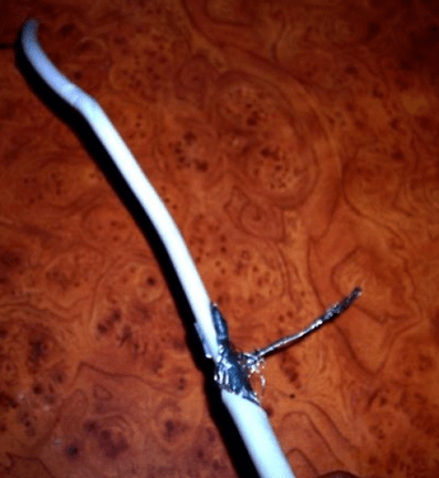
- the end of the antenna wire is stripped of insulation;
- 40 cm is measured and the insulation is carefully removed by 2 cm on the segment(it is important not to damage the outer contour);
- the bare area and the segment stripped of insulation are applied parallel to each other and firmly connected with a wire.
The result is a circle of cable with a diameter of just over 15 cm, which will serve as a receiver. Now in the middle (on the opposite side of the connection point) you need to measure 4 cm and remove the insulation. A do-it-yourself device for digital television from a coaxial cable is ready.
Such a receiver will be noisy due to the open end of the cable, so it is not suitable for continuous use. Analog TV programs are always shown with noise, but the picture quality is satisfactory.