Functional capabilities, design features, materials used and manufacturing technologies for absolute optical and magnetic rotational encoders. Rotation encoder - optical or magnetic? Translation of the publication of an interview in the Konstruktor magazine with the co-founder of the Fraba group of companies on the topic of magnetic technology.
What to look for when choosing an encoder?
Encoder reliability is very important!
Reliability and quality of operation of both your complex equipment and production as a whole depend on the reliability of the encoder. Thus, losses from unforeseen stoppages of the production line can turn out to be disproportionately high in relation to the money saved on the purchase of encoders. This includes loss of staff time, damage to production material and equipment, costs of diagnostics / troubleshooting, repair / replacement of a failed encoder and subsequent alignment and testing / startup of equipment.
When choosing an encoder, it is also important to pay attention to its technical characteristics. Some manufacturers claim high resolution, but very often they mean not physical, but interpolated resolution. Of course, one cannot expect accuracy and permissible nonlinearity from such encoders and, in some cases, the values of these characteristics are insufficient for the operation of the encoder as part of precision equipment. When choosing an encoder, it is very important to opt for proven quality.
Considering the above, we strongly recommend that you take your encoder selection seriously. Uninterrupted operation of equipment for a long time and the image of your company is only in your hands!
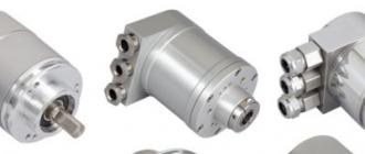
The absolute optical and magnetic rotary encoders presented in our supply program are designed and manufactured by Posital Fraba, which is world leader in the manufacture of positioning sensors and the discoverer of the method of absolute positioning of the angle of rotation. The products of the German manufacturer Posital Fraba are distinguished by the highest quality, which is guaranteed by many years (more than 80 years!) Experience in the production of absolute encoders. Positioning tasks - from industrial automation to mobile technology - require accurate and up-to-date information on the position of a particular mechanical unit.
Absolute encoders register the smallest movements and convert them into a digital signal. The ability of absolute encoders to accurately and quickly record angular and linear movements makes them the most important link between mechanics and control systems. Posital offers a wide range of mechanical encoder designs with all common types of interfaces.
Materials, technologies and experience of the manufacturer
High requirements for the materials used, taking into account different coefficients of thermal expansion, the use of bearings from trusted suppliers, special technologies for sampling backlash - all this affects such important parameters of the encoder as smoothness and ease of rotation of the shaft, durability and stability of mechanical parameters. Back in 1970, FRABA develops the world's first opto-electronic angle encoder and begins its production. Extensive experience and modern production technologies make the products of this company unsurpassed in such important parameters as: high reliability, low prices and the shortest delivery times. Over the years, a manufacturer, especially a manufacturer concentrating on the production of a narrow range of products, in this case the production of absolute encoders, has tremendous experience, its own know-how and secrets behind it.
Below are the technologies behind the Posital Fraba absolute encoders, their differences and features.
Optical encoders
The modern absolute optical encoder is an extremely complex device. When designing a high-resolution optical encoder, designers are faced with a large number of conflicting factors that greatly affect the accuracy and reliability of the encoder over a long period of time.
Optical measurement principle
A key component of optical encoders is a shaft-mounted code disc. This disc is made of a transparent material with a concentric pattern of transparent and opaque areas. Infrared light from the LED hits a series of photoreceptors through a code disc. As the shaft rotates, the unique combination of photoreceptors is illuminated by light passing through the pattern on the disc. For multi-turn models, there is an additional set of coding discs installed in the gear mechanism. As the sensor's main shaft rotates, these meshing discs rotate like a mileage counter mechanism. The rotation position of each disc is monitored optically, and the output is information about the number of revolutions of the encoder shaft.
Functionality
IXARC POSITAL optical absolute encoders use highly integrated Opto-ASIC technology, providing resolution up to 16 bits (65536 steps) per revolution. For multi-turn models, the measuring range is increased by mechanically engaging coding discs up to 16384 (214) revolutions.
Benefits of optical encoders
Optical encoders provide very high resolution and accuracy, as well as excellent dynamic performance, and are suitable for use in areas with strong magnetic fields. Since the rotation of the code discs is a completely mechanical process, these devices cannot lose information about the absolute position in the event of a temporary power outage of the device. No backup batteries required!
Encoder design
The main problem is the presence in one design of a large number of mechanical, optical and electronic interacting, but completely different in nature components. So, mechanics are prone to mechanical wear. And the quality of optical elements is influenced primarily by such factors as pollution, dimming, change in radiation intensity. The high resolution of the encoder requires the use of a high density stenciled optical disc. For optical / physical resolution (not interpolated!) Of 12 bits, a disk with sectors dividing the circle into 4096 parts / marks is required. The more compact the encoder and the smaller the disc diameter, the higher the requirements for the encoder optics. To recognize such a density of the pattern on the disc, it is necessary to place the reading matrix in close proximity to the disc. The minimum clearance between the rotating disc and the readout matrix places very high demands on the mechanics. Minimal runout / play of the shaft will lead to contact during the rotation of the disk with the readout matrix and, as a result, damage the stencil applied to the disk. Wear of the mechanical parts of the encoder or leakage of the housing also leads to contamination of the optics with wear products and dust from outside and, as a result, distortion of the measurement results. The optical disc is an important part of the encoder. Under the influence of time, temperature changes and many others. other factors, the properties of the disc material can change over time, for example, fade and deform. The first factor, combined with a losing intensity of LED backlighting, can drastically reduce the reliability of operation and / or cause a complete failure in operation. The second factor can cause the danger of contact of the disk with the matrix during the rotation of the encoder shaft with the same ensuing consequences.
Magnetic encoders
Magnetic measurement principle
Magnetic encoders determine the angular position using magnetic field technology. A permanent magnet mounted on the encoder shaft creates a magnetic field that is measured by the encoder, which generates a unique absolute position value.
Innovative multi-turn technology
IXARC POSITAL Multi-Turn Magnetic Encoders use innovative technology to keep track of the number of revolutions, even if the revolution occurred while the system was powered off. To accomplish this task, the encoders convert the rotation of the shaft into electrical energy. The technology is based on the Wiegand effect: when the permanent magnet on the encoder shaft is rotated through a certain angle, the magnetic polarity in the "Wiegand wire" changes abruptly, creating a short-term voltage surge in the winding surrounding the wire. This pulse marks the rotation of the shaft, and also provides power to the electronic circuit that registers this event. The Wiegand effect occurs in all conditions, even with very slow rotation, and eliminates the need for backup batteries.
Benefits of magnetic encoders
Magnetic encoders are reliable, durable and compact. The battery-free and gearless design provides mechanical simplicity and lower cost compared to optical encoders. Their compact size allows them to be used in very tight spaces.
Rotation encoder - optical or magnetic?
This question was once asked to the co-founder of the Fraba group of companies (who is also the director of Posital) in an interview with Konstruktor magazine when discussing the topic of introducing new magnetic technology in the production of rotary encoders.
Below is a translation of the publication of this interview.
What do experts say about the new magnetic technology?
Translation of the publication of an interview with the co-founder of the Fraba group of companies on the introduction of new magnetic technology in the production of rotary encoders
Rotary encoders convert the angle of rotation of the shaft into an electrical signal and operate on an optical or magnetic principle of operation. Optical encoders measure more accurately, while magnetic encoders are more stable and durable in design - this is a popular belief. Is this really true? The editorial staff of the Konstruktor magazine interviewed the co-founder of the Fraba group of companies and the Posital manufacturing company with 50 years of experience in the development and production of absolute encoders from Cologne.
G Ospodin Leser, are optical encoders actually more accurate than magnetic encoders?
Definitely not. Optical encoders are no longer superior to magnetic encoders in terms of accuracy. Magnetic encoder technology in recent years has made it possible to completely close the gap with the optical with respect to all important electrical parameters. Magnetic encoders available today already achieve 16-bit resolution at 0.09 ° precision and thus parameters that were previously only achievable with optical encoders. Regarding optical encoders, we speak from the position of a manufacturer of absolute optical encoders with 50 years of experience. We have been producing optical encoders since 1963 and this has always been our main specialization. In 2013, there was a real revolution in the ratio of technologies, when a magnetic encoder was presented that reached traditional optical systems in all key parameters.
What made it possible to increase the capabilities of magnetic encoders so significantly?
The key to success was a qualitative leap in technology, in which a successful combination of hardware and software of the magnetic system played an important role.
The next generation magnetic encoders are based on Hall sensors whose analog signals are processed by a fast 32-bit microcontroller in real time. Sophisticated software algorithms specially developed for the new high-tech chips by our IT specialists ensure precise calibration and guarantee the highest accuracy of the new series of magnetic encoders.
And is there also further progress in optical encoder technology, for example with regard to sensitivity to moisture, pollution, shock and vibration?
There is also further development here, but without significant leaps in the results achieved. In principle, this technology is applied in the form as it existed 50 years ago. Today's optical encoders are smaller, have higher resolution and are partially mechanically stronger and more stable than the previous generation of encoders. However, the underlying issues of sensitivity to moisture, pollution and mechanical stress remain today. Optical systems are inherently sensitive to anything that can interfere with reliable signal transmission from a light source on its way to sensitive photoreceptors. In this respect, magnetic encoders have always been ahead. Whether it is dust, fog or strong shaking, nothing can destroy the performance of a magnetic encoder so quickly.
Still, are there any applications where optical encoders are preferable to magnetic ones, for example, in terms of resistance to magnetic fields?
The noise immunity of magnetic encoders is under reliable control thanks to special mechanisms for shielding against magnetic fields. Even in the vicinity of strong sources of interference such as electronic motor brakes, our magnetic encoders work seamlessly. Thus, optical encoders no longer offer any advantages in terms of magnetic stability. We consider optical encoders only as an expensive solution for applications where extremely high resolution is required, say, 20 bits per revolution. In most cases, the accuracy of magnetic encoders is sufficient.
Which encoder technology gives mechanical engineers more design freedom?
Magnetic encoders offer noticeably more design flexibility and flexibility. They are much more compact and lighter than optical ones, which in multi-turn models are much more massive than magnetic ones due to the presence in the design of a sufficiently large gearbox consisting of several optical discs. Magnetic encoders, due to their compactness, allow them to be built into very limited spaces of a machine or other equipment. Well, another not insignificant positive factor is a more budgetary price. In a word, it is not at all surprising that magnetic encoders are the main trend now and this is recognized by most of our competitors.
Related products and articles

What is an Encoder.
An encoder or angle sensor is an electromechanical device designed to convert the angular position of a shaft or axis into electrical signals (Figure 11.1). There are two main types of encoders - incremental and absolute.
Absolute encoder
An absolute encoder disk is split into a number of sectors (most often, but not always, this number is a power of two). Sectors are divided into concentric tracks, each of which represents one bit of the coded sector number (Figure 11.2).
In this example, an absolute encoder has 32 sectors. Accordingly, to encode them, you need log 2 (32) = 5 tracks. Sector numbers are usually set Gray code... A separate sensor is required for each track on the disc.
Gray Code
The usual representation of a sequence of binary numbers is not used when building absolute encoders due to a significant drawback.
Imagine an absolute encoder, for example an 8-bit encoder (angle or linear - doesn't matter). It tracks the incremental movement of the coordinate. The change in its states is shown in table 11.1.
In the middle of the scale, when moving from a value of 127 to 128, at the output of the encoder, all the digits change simultaneously. Ideally, all the digits change at the same time. In reality, there are no two completely identical sensors, they all differ at least a little from each other in sensitivity, speed, etc .; added to this is the imperfect alignment when eight sensors are arranged in a ruler. This will cause us to expect to see any 8-bit binary number during the transition from 127 (01111111) to 128 (10000000).
Figure 11.3 shows an example of such a change in output when the state is switched from 7Fh to 10h. Instead of the transition 7Fh → 10h, one can observe the output sequence: 7Fh → 7Bh → 75h → 71h → F1h → D1h → 90h → 10h. This effect can have extremely negative consequences.

Let's assume that the encoder is in a precision drive control system. The controller, which implements control by means of a feedback loop, compares the coordinate from the sensor with the desired position of the tool and controls the servo motor that moves the tool. The drive receives a positioning command to point 128. It successfully reaches 127 and at the minimum speed, so as not to overshoot by inertia, overcomes the last step to 128.
At this moment, the encoder outputs some random coordinate value; the controller takes it as a true coordinate, calculates an offset from the desired position and issues the appropriate command to the servo motor to reduce this offset. This "phantom" offset is random and can be anything in the range from 0 to half the length of the entire ruler (assuming that we are already in the middle; we will take the average value of a quarter of the ruler as the most probable).
So, before reaching the desired position of some half a step, the servo motor makes a powerful jerk and tries to drag the carriage somewhere to the side by a quarter of the ruler. Along the way, the sensor receives the correct values, the calculated displacement decreases sharply, and the further behavior of the drive completely depends on its dynamics: a heavy and slow carriage simply does not have time to accelerate, while a light and fast one can begin to oscillate around the destination point.
All these troubles can be easily avoided by using coordinates to represent gray code... Its main feature is that when the value is increased or decreased by one, the Gray code for this value changes only in one bit. The relationship between Gray code and binary code is shown in Table 11.2.
Whichever row we choose in the table, when we move one line up or down in the Gray code, only one digit changes; therefore, even in the presence of transient processes in the sensor, the difference between the two readings will not exceed one unit, which is quite acceptable in the intermediate zone.
Incremental encoder
As the name suggests, an incremental encoder does not determine the absolute position of the disc within a full revolution, but the relative offset from the previous position. For this, a disc with a single track is sufficient (Fig. 11.4).
 |
| Fig 11.4 |

Often a second track is added with a single division per full revolution. This track allows you to set the disc to the starting position, from which the counts will subsequently be made. It can also be useful in the process of encoder diagnostics, allowing you to check the number of pulses issued by the encoder per revolution of the disk.
By counting the number of pulses from the sensor, you can determine the angle of rotation of the disk relative to the previous position; however, the direction of rotation of the disc cannot be determined. To determine the direction, a second sensor is used, offset from the first by a quarter step (half the width of the line or the gap between them). The direction of rotation of the disk is determined from the phase difference of the sensor signals.
Comparison of absolute and incremental encoders
Both types of angle encoder have their own advantages and disadvantages.
The absolute encoder can be polled any time you need to know the position of the disk, and not process the movement at each step. This simplifies work with it (in particular, makes it trivial to determine the direction of rotation of the disk), and also reduces the requirements for the controller that processes coordinate data (if the controller loses several pulses from the sensors, information about the current position of the disk will still be available).
The disadvantages of an absolute encoder, first of all, include the complexity of manufacturing associated with the presence of a large number of sensors (one for each track of the disk, that is, for each bit of the code of the angular coordinate of the disk). Also, in the case of high accuracy of the encoder (and, as a consequence, a large number of data bits), connecting the encoder to the controller will require a large number of communication lines and the same number of input bits (in the case of parallel data transmission) or the cost of additional serialization equipment (in the case of serial transmission).
In the case of an incremental encoder, the advantages and disadvantages are reversed compared to the absolute one. The advantages are: simplicity (only two sensors, regardless of resolution), relative ease in handicraft production, a small number of communication lines with the controller. Disadvantages: high demands on the speed of the controller (in case of loss of pulses from the sensors, an error will accumulate in the coordinate data), higher complexity of data processing (due to the need to determine the direction of rotation of the disk).
The simplest procedure for processing incremental encoder signals.
Before proceeding with the consideration of the decoder signal processing procedures, let's find out what these signals are.
As mentioned earlier, the decoder has two sensors: A and B. The sensors are shifted relative to each other by half the width of the bar (or a quarter of the pitch of the disk), so the signals are out of phase by p / 2. Let us assume for definiteness that signal B lags behind signal A when the disk is turned counterclockwise:
Fig. 11.5, it can be seen that when the disk moves counterclockwise (states 0-1-2-3-4 ...) at the moment when signal A transitions from state 0 to 1 (leading edge), signal B is always in state 0 (see states 0, 4, 8). If the disc is moving clockwise (7-6-5-4-3 ...), signal B is always in state 1 (states 6, 2).
This implies the simplest procedure for processing decoder signals: check the state of signal B on the leading edge of signal A; if it is 0, increment the coordinate counter by one, otherwise decrement it by one.
This algorithm is quite suitable for use in non-critical devices, when the error in determining the coordinate does not lead to fatal consequences: not so long ago, displaced by optical roller mice / trackballs, radio tape recorders, etc. decisive factor.
The reason for the imperfection of such a seemingly simple and reliable procedure lies in the fact that it requires signals of an ideal shape. In real conditions, the sensors can have "bounce" when the signal state changes (this is especially true for sensors with mechanical contacts). As a result of bounce, the coordinate will be incremented several times instead of one, and the coordinate value will be corrupted.
But, even if it were possible to get rid of the bounce completely, another problem would remain. Suppose the disc is in a position between points 3 and 4 in Fig. 3 (let's call such a point 3.5). When moving to point 4.5 at point 4, signal A goes from 0 to 1, and according to our procedure, the coordinate of the disk increases by one (since signal B is zero at the leading edge of pulse A). Then the disc goes back from 4.5 back to 3.5, but since when the disc moves back at point 4, signal A goes from 1 to 0, our procedure ignores this event.
So, we have: the disk moved a small angle and returned to its original position, and the coordinate increased by one. You can repeat this movement any number of times, and the coordinate will increase each time. As a result, the coordinate of the disk, measured by the simplest procedure, will have nothing to do with the true position of the disk.
The problem is quite urgent, since the probability of stopping the disk at the border between the light and dark zones is quite high, and vibrations during the operation of industrial equipment in combination with possible backlash of the drive may well lead to oscillations of the disk sufficient to change the state of the sensor. This makes the simplest signal processing procedure on the leading edge of signal A unsuitable for critical applications where maximum accuracy of disk coordinate measurement is required.
It should be noted that any incremental encoder has 2 types of states: stable and unstable. The stable states of the encoder are located after one period of the signal A. Non-stable states are all the others. From unstable states, the encoder easily turns into a stable one. That. only stable states can be taken as a reference point.
Sooner or later, in the life of every homemade product, there is a need to buy something so that it usually does not come to mind. So I lived in peace and did not even think about encoders.
Although I must admit I had experience with encoders. Once in one of the crafts I used an encoder from a printer.
In this story, everything happened suddenly. Crawling through their hobby forums, I came across a competition. The site (I will not name it, because the conversation is not about it) apparently carried out the promotion of attendance and plus one of the members of the forum promoted its Russian-made products. And a set of 3 sets for self-assembly of servo controllers was raffled off. I registered on this forum, submitted an application (together with 3 or 4 only participants) and ... won.
So I became the owner of 3 kits for assembling servo controllers. Next, I needed encoders. I will allow myself to explain for readers who are not so deeply immersed in electronic components what a servo controller, an encoder is and what they all eat with.
There are 2 main ways to control precise movement in CNC (Numerical Control) products. I will try to explain it in the most accessible language, without complicated schemes and terms.
The first way is with stepper motors. A stepper motor has a complex structure - several coils that attract the core in predetermined positions.


The number of positions in which the core can be fixed is called steps, intermediate positions (regulated by various intermediate voltages and, accordingly, magnetic fields) are called microsteps. A driver controls a stepper motor - this is a control board, usually with step microswitches and regulation of the current flowing through the motor. The following signals are sent to the driver input: Enable (enable the stepper motor), DIR (direction of rotation), STEP (the number of steps by which the motor needs to turn the shaft). And the driver translates the commands into the revolutions of the motor shaft. Very simple and robust design. Of the minuses - the engine speed is limited due to its design, and if the engine skips steps for one reason or another, the control program will not know about it. Hence the field of application - low and medium speed motors in a given load range. For example a 3D printer or hobby machines.
The second way to control movements is a servo motor. The motor itself can be anything, DC or AC, no difference. The only condition is that its shaft must have an encoder. An encoder is a device for determining the position of the shaft at a given time. We will talk about encoders in more detail a little later. The servo controller has a different operating principle than the stepper motor driver. The servo controller receives at the input the same signals Enable, STEP, DIR and supplies voltage to the motor. The motor starts to rotate in the desired direction, the encoder returns data on the position of the motor shaft. As the desired position is reached, the motor shaft is fixed in it. Of course, this is greatly simplified, since there is acceleration and deceleration of the motor, current and voltage control, a proportional-integral-differentiating (PID) controller in the feedback loop, ... but we agreed this time not to get too involved in theory.

What are the advantages of servo motors: any rotation speed, no skipping steps, noiselessness (a stepper motor is noticeably loud in operation due to its design). But the price of servo controllers is higher and is significantly higher for stepper motor drivers. Therefore, the main niche of servo controllers is professional use.
For my project, I chose Dynamo Sliven engines. These engines were widely used in computers in Soviet times and there were some unrealistically large numbers of them. It seems that almost any hobbyist either has such an engine or has encountered one. They are still resold at flea markets. These are DC motors with a fantastic indestructible resource and resistance to any bullying.

I used the won board as a servo controller. It is a development of an open source servo controller, known under the stable brand "Chen's servo controller" - by the name of a Chinese, so in 2004, if I am not mistaken, who proposed this scheme.

Now we are practically moving on to the essence of the review - to the encoders. The choice of the encoder was based on characteristics and price. What are the types of encoders. These are mainly optical and magnetic. Magnetic - when magnets are attached to the edges of the disc, and a Hall sensor is located near them.

The solution is expensive, industrial, and has increased reliability. The price is never a hobby.
Optical encoders. Most common solution. There is in every mouse. Previously, they were responsible for the rotation of the ball and wheel. Now the balls are gone, but the wheels remain. The principle of operation is simple - interruption of the light beam by a passing opaque body.

There are 2 types of optical encoders: incremental and absolute. Incremental subtypes are divided into 2 subtypes. The simplest incremental ones are the ones shown in the picture above. They determine the intersection of the light flux and on their basis, you can build, for example, a tachometer. The disadvantage of this encoder is that it cannot be used to determine the direction of rotation of the disk. Incremental 2-channel channels solve the problem of determining the direction of rotation of the disk.

For this, not one photodiode is used, but several, usually 4. They form 2 independent data transmission channels, and by comparing the signals from these channels, it is possible to unambiguously draw a conclusion about the direction of rotation of the disk.

What are the disadvantages of this incremental encoder? There is one drawback, but for a number of applications it is critical. When initializing the encoder, we do not know what position the disc is in. Those. we can only know the direction and speed of rotation of the disk.
To obtain complete information, namely, the initial position of the disk, the direction and speed of rotation, absolute encoders are used.


Absolute encoders use a disc with a complex position coding system. The most common Gray code is an error-proof binary encoding.
I opted for an incremental encoder with directional control, i.e. with two quadrature channels of information output. The resolution of 100 lines per revolution of the disk was for my eyes. Therefore, on Aliexpress, I found encoders for a reasonable price and with the characteristics I needed.
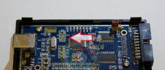
Here is a photo of 3 encoders that came to me. They arrived in 3 weeks.

Encoders have 4 pins, Red - 5V power supply, Black - ground, Colored - channels A and B.
I quickly carved a bushing on the motor shaft for mounting the disk, screwed a threaded rod into it.

On a 3D printer, I printed a pad for mounting the encoder sensor

Put it all together

I connected a servo controller, and ... there would have been a happy ending to the review, but no. Nothing worked. Nothing even came close.
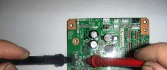
I connected an oscilloscope and realized that there were no quadrature signals at the output, only noise, interference and incomprehensible splashes. I have sinned in everything. And on the exactingness of positioning, and on exposure, and on electromagnetic interference. And for hours he neatly twisted the sensor in different positions, turned off the light and tried to do the same thing in the dark. "The crocodile is not caught, the coconut does not grow." Of course I tried all 3 encoders. It's the same everywhere. And then I was jerked to look at the sensor through a microscope.

What I saw amazed me. All 4 sensors were in a row along the radius of the disk, i.e. were illuminated through the disc slot at the same time. Of course nothing worked. The sensors should stand perpendicular to the radius of the disc and be illuminated sequentially by different fronts of the disc slot. I couldn't believe it was so simple and so stupid. The Chinese put the sensor with a 90 degree rotation. I asked on the forum a buyer like me of the same encoders as he has a sensor. And everything was also wrong for him and did not work.
After scratching my head, I decided to try to fix this matter. The encoder figured out easily, melted the hot melt glue with a hair dryer and took out the insides.

Bring the sensor to the disc so that the sensors are across the marks. Of course, the sensor did not stand up correctly, but some meaningful signal began to appear on the oscilloscope.


The photo shows that the sensors have become perpendicular to the radius of the disk.
I assembled it, connected it to the servo controller and ... Bingo, it all worked! The motor is in position hold mode. Those. when you try to turn the engine shaft, the motor rests and if it is nevertheless turned, it returns to its original position.

As a summary. The encoder does not work out of the box. I do not recommend buying. But in its price category, if it were serviceable, this is a good budget solution. Or if the alteration of the product into a working one does not frighten, then you can take and redo it.
The seller has a lot of positive reviews for such an encoder. Either this is all a linden, or, more likely, the marriage went massively recently.
I wrote to the seller, while he is sending me a ton of technical descriptions and offers to try again, and hints that I have not figured it out. I'm going to put pressure on him. Let him return at least some of the money. I spent so much time because of their factory sloppiness.
All good and pleasure from the hobby!
I plan to buy +17 Add to favourites I liked the review +120 +226The word "encoder" is of English origin. It originated from the word encode, which means "transform". The world's most famous manufacturers of these devices are such well-known brands as Siemens, SKB IS, HEIDENHAIN RLS, Baumer, SICK AG, Balluff, Schneider electric (Autonics Telemecanique), OMRON.
Scope and purpose of application
An encoder is a sensor used in the industrial field to convert the controlled value into an electrical signal. With it, for example, the position of the shaft of an electric motor is determined. Due to the fact that every device in which rotation is used must necessarily be equipped with a device that monitors the accuracy of the torque, precision motion systems are popular applications for such transducers. The main purpose for which the encoder is used is to measure the angle of rotation of an object during rotation. Encoders are indispensable in the production process at machine-tool enterprises, in work-technical complexes. They are also used in many modern ones that need to register high-precision measurements of angles, rotation, turns and tilts.

Encoder ranking
All currently known encoders are divided into absolute and incremental, resistor, magnetic and optical, operating via industrial networks or a bus interface.
Depending on the general principle of operation, there are absolute and incremental encoders. The difference between the two lies in the tasks they perform. The list of tasks of an absolute encoder is much wider than the list that is covered by an incremental encoder.
Incremental encoders
This is in the process of rotating an object at its outputs, impulses are recorded, the number of which is directly proportional to the angle of rotation of the object. Usually, incremental converters are used in the process of machine tool construction in order to register the angular displacement of a shaft or in automated systems in a feedback loop for measuring and recording the speed of rotation of a shaft.

An incremental encoder is a device that operates on the basis of these rotational pulses. The number of pulses per unit of revolution is the main operating parameter of this device. The current value is determined by the sensor by counting the number of pulses from the reference point. For the purpose of linking the reference systems, reference marks are set on the pulse encoder, which are starting after turning on the equipment. Determination of data with an incremental converter is only possible during rotation or rotation. When rotation is stopped, all encoder data are cleared to zero. As a result, upon the next power-up, the previous meter data will be unknown. For the convenience of its operation, the shaft should be brought to its original position. The incremental encoder is perfect for turning. By counting the number of pulses from the reference mark, you can also accurately determine the current coordinate of the object's rotation angle.
Absolute encoders
This is the name of the absolute. Usually in such encoders, more complex electronic signal processing processes are observed and there is an optical circuit. But on the other hand, they give out the details of the object immediately after switching on, which is often mandatory for the correct functioning of the system as a whole. Compared to incremental encoders, the use of absolute encoders allows you to solve a much wider range of tasks, since measurements are made not by means of fixing pulses, but by special digital codes. The unit of measure for such a device is the number of unique digital codes per unit of rotation (1 revolution).

Due to the fact that all digital codes issued by the sensor are unique, it is not difficult to determine the current coordinate of linear movement immediately after turning on the device and without using a reference mark. At the moment of switching on, a code of numbers appears at the outputs of the sensor. It is the designation of the current position of the object's rotation angle. Thus, an absolute encoder does an excellent job not only with the task of tracking the speed of rotation (rotation) of an object, but also gives correct data about its exact location at a given time, regardless of whether it is connected or not.
Varieties of absolute encoders
Depending on the characteristics of the characteristics, absolute encoders can differ in the type of mounting, the presence of a blind or through, hollow or protruding shaft. The range of such devices is also very diverse in terms of external characteristics: length, body diameter, and so on. In addition, it is known that the absolute positions during rotation are multi-turn and single-turn. Single-turn ones make the determination of the current coordinate within 1 turn, and multi-turn ones are capable of recognizing several more additional turns.
Optical encoder - what is it?
This transducer is a disk made of glass rigidly fixed to the shaft. The optical encoder, in contrast to the above-described sensors, is additionally equipped with an optical raster, which, during the rotation of the shaft, moves and converts the torque into a stream of light, which is subsequently received by the photosensor.

This type of transducer fixes the angles of rotation, where each unique position corresponds to a special unique code of numbers. Together with the number of revolutions, it represents the unit of measurement for the sensor. The encoder connection and operation are identical to the operation of the incremental device described above.
Sensor types depending on the principle of operation
According to the characteristics of their work, encoders are divided into magnetic and photoelectric.
The physical principle of operation of the first is based on the application of E. Hall discovered in 1879. In this case, the potential difference arises only when the direct current conductor is placed in the area of the magnetic field.
In terms of resolution and accuracy, a magnetic encoder is inferior to a photoelectric one, but its implementation is simpler. It is much less demanding in terms of space and operating conditions.
The representative of the magnetic encoder is a device that records the cycle of passage of the magnetic pole of a rotating magnet located near the sensing element. The transmitter data expression is also in the form of a digital code.
A photoelectric encoder is a sensor that operates on the basis of the photoelectric effect, which is observed as a result of the action of light on a substance. This principle was discovered in 1887 by G. Hertz. During the operation of this type of sensor, a constant transformation of the light beam into an electrical signal is observed.

Photoelectric encoder is synonymous with optocoupler, optical and optoelectronic. Sensors of this type are more demanding in terms of production, operation and much more than other encoders, but this is justified, since the potential for their accuracy is much higher than that of competitors.
An encoder / transducer of angular displacements is a device designed to convert the angle of rotation of a rotating object (shaft) into electrical signals that allow determining the angle of its rotation.
They are widely used in industry.
Encoders are classified into incremental and absolute encoders, which can achieve very high resolution.
An incremental encoder generates a specified number of pulses per revolution. And absolute encoders allow you to know the current angle of rotation of the axis at any time, including after power failure and restoration. And multiturn absolute encoders also count and store the number of complete revolutions of the axis.
Encoders can be either optical, resistor or magnetic and can be operated via bus interfaces or fieldbus.
Angle-code converters have almost completely replaced the use of selsyns.
Incremental encoders
Incremental encoders are used to determine the angle of rotation of rotating objects. They generate a sequential pulsed digital code containing information regarding the angle of rotation of the object. If the shaft stops, then the transmission of pulses also stops. The main operating parameter of the sensor is the number of pulses per revolution. The instantaneous value of the angle of rotation of the object is determined by counting the pulses from the start. To calculate the angular velocity of an object, the processor in the tachometer differentiates the number of pulses in time, thus immediately showing the magnitude of the speed, that is, the number of revolutions per minute. The output signal has two channels, in which identical pulse sequences are shifted by 90 ° relative to each other (paraphase pulses), which makes it possible to determine the direction of rotation. There is also a digital zero mark output that always calculates the absolute position of the shaft.
The principle of operation of encoders
Angular displacement transducers are used to measure the main kinematic parameters of the electric drive: speed and position of the shaft. In the recent past, DC and AC tachogenerators or selsyns were used for most of these measurement tasks.
This is what Ukrainian researchers A.S. Kurskiy, R.Yu. Kaydash and D.A. Denisenko state in their work. had a lot of shortcomings. The introduction of discrete pulse sensors has helped to eliminate many of the disadvantages inherent in analog technology. Photopulse sensors have great advantages in almost all parameters (accuracy, dimensions, reliability, efficiency) ... The use of photopulse sensors expands the capabilities of the electric drive ... "*.
The vast majority of today's variable speed drive, positioning and angle control systems use incremental and absolute encoders. A certain market, due to some technical features, remains with the resolvers (in particular, because of their tolerance to high and low temperatures: from -50 o C to +150 o C).
The principle of operation of photo-pulse encoders is digital. Light travels from a group of LEDs to a group of photodiodes through a transparent disc with markings. An absolute encoder has a unique combination of marks for each angular position, an incremental encoder is simpler: the same marks are evenly distributed over the entire radius of the disc.
Usually the encoder also has a so-called. "Zero mark", one - for a complete revolution of the disk. This mark has a calibration function and is not always required for simple speed measurement tasks. When the disk rotates, which is mechanically connected to the drive shaft, each pass of the tag through the LED pair generates a pulse. These pulses are further processed by electronic devices (programmable logic controllers, AC and DC converters for electric motors, counters).
Absolute encoders sometimes have a built-in gearbox, which allows the encoder not only to determine the exact value of the angular displacement within one revolution of the shaft, but also to count the number of shaft revolutions (usually with a resolution of 12 bits, i.e. 4096 shaft revolutions). These absolute encoders, called “absolute multiturn”, are often used in precision worm feed drives.
Encoder |
|

Program "; Encoder"; is designed to measure the relative position (displacement), speed and direction of movement using optical displacement sensors(encoders) connected to input channels ADC modules and spectrum analyzers.
On the basis of optical sensors, linear and angular displacement sensors are created. The accuracy of such sensors can be from 1 μm to 1 mm with a length of the measuring base from 8 mm to 3 m. Angular displacement sensors can have from 100 to 10,000 markers per revolution, i.e. the resolution can be up to 5 minutes.
Optical technology has proposed a number of classical methods for constructing an encoder - a sensor that provides information about movement, position or direction either directly in digital form, or generates a sequence of pulses from which, after digitization, a digital code can be formed.
|
|


The principle of operation of the encoders is illustrated in Figure 1. An optical encoder consists of a thin optical disc and a stationary unit - a measuring head, which includes a light source and a photodetector. The optical disc includes a surface of transparent and opaque areas. Markers can be, for example, holes in a sheet of metal or marks on a glass disc. When the disc rotates, depending on its type, the markers transmit or block the light beam directed from the light source to the photodetector.
The photodetector generates a signal with a frequency equal to the repetition rate of the chips in digital form or an analog pulse signal, which can also be amplified and digitized. When adding the second pair "; LED-phototransistor"; with an angular displacement relative to the first, corresponding to a quarter of the signal period, a second sequence of pulses can be obtained - channel B with a phase shift relative to channel A by 90 °. An incremental encoder that uses three optical encoders allows simultaneous doubling of the resolution for position and speed measurements and direction detection.

Picture 1
Linear and angular displacement transducers are directly connected to ADC modules. The generator output can be used to power the sensors. The resolution of incremental encoders is measured in pulses per revolution (ppr). In the program "; Encoder"; the user is given the opportunity to select the resolution of the encoder used (window "; Resolution, labels / e.i.";). "; E. and."; - unit of measurement that can be selected from the series "; mm, cm, m, gr. (degrees), rev. (revolutions)"; or spelled out manually in the window "; Unit of measurement" ;.
Incremental encoders
Incremental encoders are used to determine the angle of rotation of rotating objects. They generate consistent pulse digital code containing information regarding the angle of rotation of the object. If the shaft stops, then the transmission of pulses also stops. The main operating parameter of the sensor is the number of pulses per revolution. The instantaneous value of the angle of rotation of the object is determined by counting the pulses from the start. To calculate the angular velocity of an object, the processor in the tachometer differentiates the number of pulses in time, thus immediately showing the magnitude of the speed, that is, the number of revolutions per minute. The output signal has two channels, in which identical pulse sequences are shifted by 90 ° relative to each other (paraphase pulses), which makes it possible to determine the direction of rotation. There is also a digital zero mark output that always calculates the absolute position of the shaft.
|
 digital optical encoder is a motion converter into a sequence of digital pulses. By decoding the bit sequence, digital pulses can be converted to relative or absolute measurement data. The encoder can be linear or rotational, with the latter configuration being the most common.
|
Many years of experience show that if a large production is at a standstill, the necessary measures to localize and eliminate the malfunction must be taken with lightning speed. Very often the cause of an accident is the failure of the electric drive, especially if it is not equipped with energy-saving automatic speed control and regulation systems.
Manufacturing and technical firm "; Consis"; is an integrator of solutions in the field of controlled electric drives, and one of its most important elements responsible for the accuracy of the drive automation are angular displacement encoders, also called angle encoders or encoders (from the English encoder - "; encoder";). Encoders are widely used in any industry. Absolute and incremental encoders are installed on drives of paper-making and board-making machines, pressing machines, packaging units, forestry machines and woodworking machines, longitudinal and cross-cutting (chipper) machines, rolling mills, on drives of elevators and cranes, lathes and coordinate tables is available for any powerful electric drive. This material is dedicated to encoders manufactured by the Swedish company Leine & Linde, which is one of the five leading global manufacturers of angle encoders.
The principle of operation of encoders
Digital photopulse encoders are used to measure the main kinematic parameters of the electric drive: speed and position of the shaft. In the recent past, selsyns or tachogenerators of direct and alternating currents were used for this. Digital sensors have great advantages over analog sensors in almost all respects. Most modern variable speed drive systems use incremental and absolute encoders for positioning and angular position control.
In photodiode sensors, light travels from emitting LEDs to photodiode detectors through a transparent disc with markings. An absolute encoder has a unique combination of marks for each angular position, and on an incremental encoder, the same marks are evenly distributed over the disk. When the tags pass through the LED pair, pulses are generated, which are further processed using electronic devices (programmable logic controllers, DC and AC current converters for electric motors, counters).
The main advantage of an absolute encoder over an incremental encoder is the function of storing the current value of the angular displacement, regardless of whether the encoder is powered or not.
Basic parameters required to select an encoder:
- the number of pulses per revolution (usually from 1 to 5000);
- the number of bits for absolute encoders (usually 10, 12, 13, 25);
- diameter of the shaft or shaft hole;
- type of output signal (HTL, TTL, RS422, binary code and Gray code, SSI, Profibus DP, CAN ...);
- supply voltage;
- cable length and connector type;
- additional requirements for fasteners (the need for a coupling, mounting flange, mounting rod, etc.).
Accurate alignment when installing sensors is a key requirement to ensure long-term performance. Encoder version with shaft
 (fig. 1) provides for the installation of a precision flanged coupling to absorb angular misalignment, axial runout and shaft misalignment during installation. Rigid shaft connections can lead to significant bearing wear.
Hollow rotor encoder version
 (fig. 2) excludes the use of a coupling and a flange. The encoder is mounted directly on the non-working end of the motor shaft and is secured to the housing by means of a rod against rotation behind the shaft.
Hollow shaft encoders are becoming more common nowadays - they are easier to install, more convenient to set up and maintain. It should be noted that the service life of the encoder, with correct installation and connection, should be at least 50,000 hours, i.e. almost 6 years.
The table provides a comparative description of the two fastening systems.
Shaft encoders | Hollow rotor encoders |
|
Installation | Requires more accessories and accurate alignment; takes up more space (coupling + sensor shaft + sensor housing) | A large number of accessories are not required; precise alignment of the shaft on which the encoder is mounted is required; takes up less space |
Resistance to misalignment | Very limited, depending on the selected coupling | High at low revs, limited at high |
Consequences of inaccurate alignment | Load on bearings and coupling, large error will shorten service life. Gives an error in angular measurement depending on the type of coupling | The dynamic load on the bearings increases exponentially with increasing shaft speed. The measurement error is proportional to the alignment error and is directly related to it. |
Axial runout resistance | Limited | Very good |
101% quality
In order to illustrate the advantages of Leine & Linde encoders, we will tell you about the sequence of tests that the sensors are subjected to.
The first thing to check is its performance, while all its electrical parameters are measured. Frequency range, signal accuracy, short circuit protection and maximum load are just a few of them. After that, the encoder is tested in a climatic chamber, on a vibration bench and in an electromagnetic compatibility laboratory.
The climatic chamber maintains temperatures from -60 to +150 ° C. Each test can include up to 20 temperature cycles. Vibration resistance of encoders is checked along three orthogonal axes, one of which is parallel to the sensor shaft. Three vibration amplitudes are applied to the encoder: 100, 200 and 300 m / s2. The time for a standard test is 3 cycles of 20 hours. The vibration level that the sensor is subjected to during the tests is significantly higher than the vibration level under normal industrial conditions. Electromagnetic compatibility (EMC) is, firstly, the requirement for immunity to electromagnetic interference, and secondly, the restrictions imposed on equipment as a source of electromagnetic interference. Encoders are also subjected to long-term wear tests. The test involves working at the maximum permissible speeds for a long time.
The product testing process at the Leine & Linde factory is a very important part of ensuring product quality and high technical level. It comes as no surprise that Leine & Linde rotary encoders are renowned for their high quality, robustness and operational reliability.
PTF "; Consis"; being the official distributor of Leine & Linde in Russia, guarantees that any encoder from the Leine & Linde product line can be assembled at the factory and sent to the customer as soon as possible, up to one working day.
If you also require high quality, operational reliability and optimal delivery times, we highly recommend trying to work with Leine & Linde encoders.
Andrey Boskis
AVR. Training course. Incremental encoder.
An encoder is just a digital angle sensor, nothing more.
There are absolute encoders - they immediately give out the binary code of the angle and incremental, giving only an indication of the direction and frequency of rotation, and the controller, counting the pulses and knowing the number of pulses per revolution, will determine the position itself.
While everything is simple with an absolute encoder, there are difficulties with an incremental encoder. How to handle it?
Two signals A and B are output from the Encoder, shifted by 90 degrees in phase, it looks like this:
In the optical, there can be two flashlights and two photodiodes, shining through a disc with slots (ball mouse, yeah. It's the same).
The mechanical one connects quite simply the central one to the ground, the two extreme (channels) to the pulled-up ports. For reliability, I connected an external brace. Good for me Pinboard to do this, just click with a couple of toggle switches:
|

Optical is connected depending on the type of optosensor, usually there are two photodiode with a common anode.
Usually, everyone tries to work with them through INT interrupts, but this method is so-so. The problem here is bounce - mechanical contacts, especially after prolonged use, begin to malfunction and false impulses at the time of switching. And the interruption for these false impulses will still work and consider that something is wrong.
The method is simple:
Substitute zeros and ones according to the signal level and write down the code sequence:
|

A: 0 0 1 1 0 0 1 1 0 0 1 1 0
B: 1 0 0 1 1 0 0 1 1 0 0 1 1
If A and B go to the same controller port (for example, A = PB0 B = PB1), then when the encoder rotates, we have a changing code:
11 = 3
10 = 2
00 = 0
01 = 1
11 = 3
Now it remains only to cyclically poll our encoder comparing the current state with the new one and, based on this, draw conclusions about the rotation. Moreover, the polling frequency should be such as not to miss a single pulse. For example, my EC12 has 24 pulses per revolution. It is supposed to rotate it manually, and I can hardly rotate it at cosmic speed, but I decided to measure it anyway. I connected to the oscilloscope, turned the knob that I could eat:
|

Squeezed out less than a kilohertz. Those. you need to poll about 1000 times per second. It may even be less common, it will be more reliable in terms of possible bounce. Now, by the way, there is almost no chatter, but it is far from the fact that it will not be later, when the device looses.
The poll itself must be in the form of a state machine. Those. we have the current state and two possible next ones.
// This task should be run every millisecond. // EncState global variable u08 - previous state of the encoder // EncData global variable u16 - encoder count register void EncoderScan (void) New = PINB & 0x03; // Take the current value // And compare with the old one // Looking in which direction it has changed - we increase // Or decrement the counting register switch (EncState) if (New == 3) EncData ++; if (New == 0) EncData--; if (New == 2) EncData ++; if (New == 1) EncData--; if (New == 0) EncData ++; if (New == 3) EncData--; if (New == 1) EncData ++; if (New == 2) EncData--; EncState = New; // Write the new value // Previous state SetTimerTask (EncoderScan, 1); // Restart the task using the dispatcher timer |
Why did I put such a large variable under the counter? Two whole bytes? Yes, the whole point is that my encoder, in addition to impulses, also has tactile clicks. 24 pulses and 24 clicks per revolution. And according to my logic, there are four state changes per pulse, i.e. full period 3201_3201_3201 and one click gives 4 divisions, which is ugly. So I count to 1024 and then divide by four. We get one lye at the exit - one tick.
High-speed interrupt polling
But these are mechanical, you can do with them by simple polling - the pulse frequency allows. And there are also high-speed encoders. They give several thousand pulses per revolution, or they run on drives and rotate very quickly. What to do with them?
Accelerate polling is a dead-end activity. But we are saved by the fact that such encoders, as a rule, already have their own schemes for suppressing bounce and uncertainty, so that at the output they have a clear rectangular signal (though they cost quite inhumanely. From 5000r and up to several hundred thousand. wanted - industrial equipment is never cheap).
So you can use interrupts without any problems. And then everything becomes incredibly simpler. We configure just one interrupt for an external signal. For example, we set INT0 so that the trigger is on the rising edge. And we send to INT0 channel A.
|

The dotted line shows the expected position at an arbitrary moment. Red arrows are fronts along which interrupts will be triggered when moving either in one direction or in the other direction.
And in the INT0 interrupt handler, we probe channel B with the second pin. And then everything is elementary!
If there is a high level, we do +1, if the low is -1 for our counting register. The code is three lines, I'm even too lazy to write it.
Of course, this method can also be screwed onto a mechanical encoder. But here it will be necessary to block INT0 interrupts for a few milliseconds. And IN NO CASE you can do it in the handler.
The debouncing interrupt algorithm will look like this:
Denied INT0 locally
Set the timer to an event that resolves INT0 after a few milliseconds
The synthesizer is designed for work v devices with an intermediate frequency ... you can also find other names encoders with identical principlework... Polar electrolytic capacitors, the rest ...
Elements and functional devices of automation systems
Abstract... principles their work. Principlework amplitude detector is explained in Fig. 25. Device... absolute displacements, absolute encoders... Position sensors, positioning sensors ... - not magnetic, etc. Encoders available in different types: tachometric (...
Llc "rusuchpribor"
DocumentShaft (based on incremental encoder); strain gauge complex for ... shaft (based on incremental encoder); strain gauge complex for ... devices and principleswork microprocessor-based on-board control system ...
Use the information for job search, selection of training and retraining of personnel! help in finding a job and recruiting staff on the website / for training and retraining personnel, you can contact
Document... principlework proportional pressure valve; - Electrohydraulic amplifiers; - Construction and principlework proportional chokes and valves; - Construction and principlework... executive devices; -Principles ... encoder ...
We entered the INT0 handler
We felt the second channel