Failure of the regulator relay is the most common cause of malfunctioning automotive alternators. That is why, with checking the regulator, they usually begin to monitor the performance of the generator units.
In most cases, you can do it yourself, even without removing it.
The principle of operation of the generator voltage regulator
The generator is one of the most conservative parts of a car. The circuit developed in the mid-60s has remained practically unchanged up to the present day, with the exception of the element base.
Scheme
In general, the diagram of a car generator can be depicted as follows:
It contains the following main nodes:
- rectifier bridge 5 and 6;
- rectifier bridge power supply relay-regulator 7;
- field winding brushes 10;
- excitation winding (armature) 9;
- stator winding 8;
- indicator lamp 4;
- accumulator battery 3;
- contact group of the ignition lock 1;
- capacitor 2 (optional).
General principle of operation of generators alternating current invented by the brilliant Tesla. D.C induces a magnetic field through the excitation winding. During the rotation of the excitation coil (armature) inside the stator winding, an alternating voltage is generated in the latter.
This voltage is converted into a constant rectifier made on the diode bridge 5 and 6. Rectified voltage.
The higher the current in the field winding, the higher the generator voltage will be.
What is the function of the relay controller? It is essentially an amplifier with feedback... That is, as soon as the voltage rises, its circuit reduces the current through the field winding.
Accordingly, the generator voltage decreases. Then it increases the winding current, the generator voltage increases. And so on ad infinitum. Ultimately, the generator voltage will stabilize at a certain level. This whole stabilization process takes a split second.
Kinds
Relay-regulators classify by element base execution:
- relay;
- transistor-relay;
- transistor (in cars up to the 90s);
- integral (in modern cars);
- microprocessor-based with program control (Audi, BMW).

By design:
- external, fixed on body elements;
- built-in;
- built-in, combined with brushes.

In modern cars, devices combined with brushes are most often used. This has its drawback: when the brushes wear out, the relay regulator has to be changed. Conversely, failure of the regulator relay can lead to replacement of healthy brushes.
Some specialists change only the brushes located in conjunction with the relay-regulator. Is not the best option for reasons of reliability, the more the cost of the relay-regulators of common cars is not so high and may even be lower than the cost of replacing the brushes.
Possible causes of malfunction
The main causes of malfunctions of voltage regulator relays of generators are considered:
- turn-to-turn closure of the excitation winding. Most dangerous cause of failure. After replacing the relay-regulator, the generator works for a certain time without problems. But the regulator works at high currents and burns out again after a couple of months. In this case, it is necessary to remove the generator and take it for testing;
- failure of the rectifier bridge (breakdown of diodes). Less dangerous, the more this malfunction causes the generator to overheat, and the diodes change first;
- polarity reversal or reversed battery poles. In this case, the rectifier diodes also fail;
- destruction of brushes;
- short circuit at the control output of the relay-regulator;
- natural wear and tear.
The consequences of a faulty relay regulator can be significant:
- the increased voltage of the generator can lead to the failure of the electronic units of the car, therefore it is impossible with the engine running;
- internal short circuit of the relay-regulator leads to overheating of the field winding and, ultimately, more expensive repairs;
- the destruction of the brushes of the relay-regulator can cause permanent damage to the generator, its jamming, a broken belt and more serious consequences.
The main symptoms of a malfunction
The very first symptom of a malfunction is the absence of a warning light (indicator) on the dashboard when the ignition is turned on.
In older cars, where the battery charging circuit is similar to that shown in the first figure, it is too early for motorists to panic. Perhaps it is just a light bulb burned out or contact is broken, and these cases are quite common. Car owners remove the generator, take it for testing, but in vain.
The second symptom is that the “battery” indicator does not go out after starting the engine. This already indicates a violation of the charging process and a possible malfunction of the generator.
Another sign of a malfunction is that the brightness of the low-high beam depends on the engine speed. By the way, this check is recommended to be done regularly. To do this, it is necessary at night to stop in an uninhabited place in front of a building and turn on the neutral train by turning on the high beam. A change in brightness indicates possible problems with charging system.
The smell of a burnt winding in the passenger compartment is also a sign of a malfunctioning generator, but you may not feel it.
How to independently check the generator relay-regulator with a multimeter or lamp
In case of suspicion of a malfunction of the battery charging system, the test should begin with monitoring the voltage on the battery with the engine running. It should be in the range of 13.3 - 14.5 Volts. A voltage of more than 15 volts is a sure sign of a malfunction of the relay regulator.
Video - how to test a relay regulator without a regulated power supply:
Sometimes there is another one to control the tachometer. Ring the control wire to ground. A resistance below 10 ohms will also indicate a malfunction of the relay-regulator.
The following checks should be performed on the relay-regulator removed from the generator. In most cases this can and should be done without dismantling the generator. The regulator relay is usually attached to the generator with two to three bolts or screws.

After that, you need to assemble a simple circuit.

or another version of it

You can use an ordinary salon lamp as a light bulb. Its glow will indicate the serviceability of the relay-regulator. On the removed relay, you should also check the condition of the brushes.
On the Internet, you can find test schemes for almost any type of generator voltage regulator relay.
In the event that the test results are negative, the regulator should be changed. Usually its cost does not exceed 2,000 rubles for common brands.
At the slightest suspicion of a malfunction of the battery charging system (change in the brightness of the lights, blinking of the indicator lamp, difficulty starting the engine, overheating of the device, etc.), you should immediately check the generator's performance, especially in the cold season.
In order for the generator to last longer, follow these simple rules:
- do not allow excessive contamination of the generator (it has technological holes for ventilation, dirt can get there), clean its surface;
- periodically check the belt tension;
- monitor the condition of the stator windings, this can be done through the technological holes, they must not be darkened;
- poor contact of the control wire can lead to failure of the relay-regulator;
- to prevent battery overcharge and damage electronic systems periodically check the battery voltage with the engine running (charge voltage).
And let your generator last longer!
Video - how to check the voltage regulator of the VALEO alternator in Renault vehicles:
May interest:
Unique Automotive Scanner Scan Tool Pro
Electromechanical, in which, with the help of vibrating contacts, the current in the excitation winding of the alternator is changed. The operation of the vibrating contacts is ensured in such a way that with an increase in the voltage of the on-board network, the current in the field winding decreases. However, vibration voltage regulators maintain voltage with an accuracy of 5-10%, which significantly reduces the life of the battery and car lighting lamps.
Electronic voltage regulators of the on-board network of the Y112 type, which are popularly called "chocolate". The disadvantages of this regulator are known to everyone - low reliability due to the low switching current of 5A and the place of installation directly on the generator, which leads to overheating of the regulator and its failure. The voltage maintenance accuracy remains, despite the electronic circuitry, very low and amounts to 5% of the nominal voltage.
That is why I decided to make a device that is free from the above disadvantages. The regulator is easy to adjust, the voltage maintenance accuracy is 1% of the nominal voltage. The circuit shown in Fig. 1 has been tested on many vehicles, including trucks, for 2 years and has shown very good results.

Fig. 1.
Principle of operation
When the ignition switch is turned on, + 12V voltage is supplied to the electronic regulator circuit. If the voltage supplied to the Zener diode VD1 from the voltage divider R1R2 is not enough for its breakdown, then the transistors VT1, VT2 are in the closed state, and VT3 is in the open. A maximum current flows through the excitation winding, the output voltage of the generator begins to rise and when it reaches 13.5 - 14.2V, a Zener diode breakdown occurs.
Thanks to this, the transistors VT1, VT2 open, respectively, the transistor VT3 closes, the field winding current decreases and the output voltage of the generator decreases. A decrease in the output voltage by about 0.05-0.12V is enough for the zener diode to go into a locked state, after which the transistors VT1, VT2 close, and the transistor VT3 opens and current begins to flow through the excitation winding again. This process is continuously repeated at a frequency of 200 - 300 Hz, which is determined by the inertia of the magnetic flux.
Design
When making an electronic regulator, you should pay special attention to heat removal from the VT3 transistor. At this transistor, operating in the key mode, 1, however, significant power is released, so it should be mounted on a radiator. The rest of the details can be placed on printed circuit boardattached to the radiator.
This results in a very compact design. Resistor R6 must be at least 2W. The VD2 diode must have a forward current of about 2A and a reverse voltage of at least 400V, KD202Zh is best suited, but other options are also possible. It is advisable to use transistors those indicated in the circuit diagram, especially VT3. Transistor VT2 can be replaced with KT814 with any letter indices. It is advisable to install a VD1 Zener diode with a KS series with a stabilization voltage of 5.6-9V, (type KS156A, KS358A, KS172A), while the accuracy of maintaining the voltage will increase.
Setting up
A properly assembled voltage regulator does not need special tuning and ensures the stability of the on-board network voltage of about 0.1 - 0.12 V, when the engine speed changes from 800 to 5500 rpm. The easiest way to do the setting is to do it on a stand consisting of an adjustable power supply 0-17V and a 12V 5-10W incandescent light bulb. The positive output of the power supply is connected to the “+” terminal of the regulator, the negative output of the power supply is connected to the “Common” terminal, and the incandescent light is connected to the “Ш” and “Common” terminals of the controller.
The setting is reduced to the selection of the resistor R2, which is changed within 1-5 kΩ, and the response threshold is achieved at the level of 14.2V. This is the supported voltage of the on-board network. It is impossible to increase it above 14.5V, since this will sharply reduce the battery life.
The electrical equipment of any car includes a generator - a device that converts mechanical energy received from the engine into electrical energy. Together with the voltage regulator, it is called a generator set. Alternators are installed on modern cars. They meet the requirements to the greatest extent.
What is a generator voltage regulator?
Maintains the voltage of the on-board network within the specified limits in all operating modes when changing the rotational speed of the generator rotor, electrical load, ambient temperature. In addition, it can perform additional functions - to protect the elements of the generator set from emergency modes and overload, to automatically connect the field winding circuit or the alarm system for the emergency operation of the generator set to the on-board network.
The principle of operation of the voltage regulator
 All gensets are now equipped with semiconductor electronic voltage regulators, usually built into the generator. The schemes of their execution and design may be different, but the principle of operation is the same for all regulators. The voltage of a generator without a regulator depends on the frequency of rotation of its rotor, the magnetic flux created by the excitation winding, and, consequently, on the strength of the current in this winding and the magnitude of the current given by the generator to consumers. The higher the rotation frequency and the excitation current, the higher the generator voltage, the higher the current of its load, the lower this voltage.
The function of the voltage regulator is to stabilize the voltage when the speed and load change by acting on the excitation current. Of course, you can change the current in the excitation circuit by introducing an additional resistor into this circuit, as was done in the previous vibration voltage regulators, but this method is associated with a loss of power in this resistor and is not used in electronic regulators. Electronic controllers change the excitation current by turning on and off the excitation winding from the mains, while the relative duration of the excitation winding switching-on time changes. If, to stabilize the voltage, it is required to reduce the field current, the time to turn on the field winding decreases, if it is necessary to increase it increases.
Checking the voltage regulator
Before checking the voltage regulator, you need to make sure that the problem lies in it, and not in other elements of the generator (the belt is loose, the mass is oxidized, etc.), for this you need to check the generator itself (How to check the generator?). After that, you need to remove the voltage regulator. The process of dismantling the regulator is described in the article "How to remove the voltage regulator?". In a nutshell, I will say that first you need to remove the negative terminal, remove all wires from the generator, remove the plastic casing from the generator, then unscrew and remove the voltage regulator assembly along with the brushes.
 Let's go directly to testing the voltage regulator. It is imperative to check the voltage regulator assembled with brush holders. in the event of an open circuit of the brushes and the voltage regulator, we will immediately notice this. Before checking, pay attention to the condition of the brushes: if they are broken off or their length is shorter than 5mm, motionless and not springy, then they must be replaced. To check, we need:
- wires;
- car battery;
- a bulb for 12V 1-3W;
- two ordinary finger-type batteries.
To test the voltage regulator, we will need to build two circuits: We connect the light bulb to the brushes, connect the “+” from the battery to the terminals B and C, fasten the “-” battery to the regulator's ground. We do the same scheme, but add two finger batteries in series. The conclusion from all of the above is as follows. Working voltage regulator: in the first circuit the lamp is on, in the second circuit the lamp is off, because voltage is higher than 14.7v and the voltage supply to the brushes must be stopped. Defective voltage regulator: in both cases the lamp is on, which means there is a breakdown in the regulator. The lamp does not light at all - it means there is no contact between the brushes and the regulator or an open circuit in the regulator.
Three-level voltage regulators
First, let's find out what this regulator is for. The car generator must supply the battery while driving and running the engine. This restores the capacity of the battery when it is discharged while stationary. If we drive every day, then the battery is almost never discharged if it is in good condition.
 The battery is worse when the car stands still for a long time, because its energy is gradually spent on maintaining the auto alarm. The situation is even worse in winter, when at negative temperatures the battery is discharged very quickly. And if you drive little and not often, the battery does not fully charge while driving and may be completely discharged one morning.
To cope with the above problem, a three-level voltage regulator is designed. He has three work positions:this is the maximum(gives a voltage on the generator 14.0-14.2 V), normal (13.6-13.8V) and minimal (13.0-13.2V). As we know from the article about checking the battery's performance, the normal voltage with the engine running should be from 13.2-13.6 V. This means that the generator is operating in normal mode and the battery is fully charged.
This corresponds to the middle (normal) position of the voltage regulator. But in winter, it is advisable to increase the voltage to 13.8-14.0 V, because the battery discharges faster in freezing temperatures. This is done by simply moving the lever on the voltage regulator. So it will be provided best charge Battery in winter with the engine running.
In the summer, especially when the heat exceeds +25 degrees and above, it is advisable to lower the generator voltage to 13.0-13.2 V. Charging will not suffer from this, but the generator will not “boil off”, i.e. will not lose its nominal capacity and will not reduce the resource.
How to remove or replace a voltage regulator?
Before replacing the voltage regulator, be sure to check the generator as a whole (How to check the generator?). The voltage regulator must be changed if the voltage under the load of the on-board network (the distant one, heated mirrors, stove are on) is less than 13v. Also, the voltage regulator can cause high voltage (above 14.7v). But, as stated above, before removing the regulator, you need to check the generator itself, get acquainted with other possible malfunctions (for example, the generator belt is loosely tensioned), and only then proceed to replace the voltage regulator. You will also need this article to replace the generator brushes. brushes and voltage regulator are installed on the generator assembly.
 So how do you remove the voltage regulator? Open the hood, remove the negative terminal of the battery, find the generator, disconnect the "D" wiring block.
- Remove the protective rubber cap from the terminals of the wires of the "+" output. We unscrew the nut securing these wires, remove them from the generator block.
We find the voltage regulator, and use a Phillips screwdriver to unscrew its fasteners.
We take out the voltage regulator assembly with brushes, and disconnect the block of wires from it.
We install the voltage regulator in strictly reverse order. It should be noted that in recent times, many motorists began to use a three-level voltage regulator in order to get rid of voltage drops in the on-board network.
Subscribe to our feeds in
The generator voltage regulator relay is an integral part of the electrical system of any car. With its help, the voltage is maintained within a certain range of values. In this article, you will learn about what regulator designs exist at the moment, including mechanisms that have not been used for a long time.
Basic automatic regulation processes
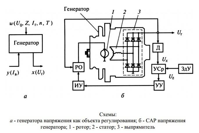
It doesn't matter what type of generator set is used in the vehicle. In any case, it has a regulator in its design. The automatic voltage regulation system allows maintaining a certain value of the parameter, regardless of the frequency with which the generator rotor rotates. The figure shows the generator voltage regulator relay, its diagram and appearance.
Analyzing physical foundations, with which the generator set operates, it can be concluded that the output voltage increases if the rotor speed becomes higher. It can also be concluded that voltage regulation is carried out by reducing the current supplied to the rotor winding when the rotation speed is increased.

What is a generator
Any car generator consists of several parts:
1. A rotor with a field winding, around which an electromagnetic field is created during operation.
2. A stator with three windings connected in a "star" scheme (alternating voltage is removed from them in the range from 12 to 30 volts).
3. In addition, the design includes a three-phase rectifier, consisting of six semiconductor diodes. It is worth noting that the voltage regulator relay for the VAZ 2107 generator in the injection system is the same.
But the generator cannot work without a voltage regulator. The reason for this is the voltage change in a very wide range. Therefore, it is necessary to use an automatic control system. It consists of a comparison device, a control, an executive, a master and a special sensor. The main element is the regulatory body. It can be both electrical and mechanical.

Generator operation
When the rotor starts rotating, some voltage appears at the output of the generator. And it is fed to the excitation winding by means of an adjustment element. It is also worth noting that the generator set output is directly connected to the battery. Therefore, voltage is constantly present on the field winding. As the rotor speed increases, the voltage at the generator set output begins to change. The voltage regulator relay of the Valeo or any other manufacturer is connected to the generator output.
In this case, the sensor catches the change, sends a signal to the comparator, which analyzes it, comparing it with a given parameter. Further, the signal goes to the control device, from which it is fed to the Regulator, which is able to reduce the value of the current that is supplied to the rotor winding. As a result, the voltage at the output of the generator set is reduced. Similarly, the above parameter is increased in the case of a decrease in the rotor speed.
Two-level regulators
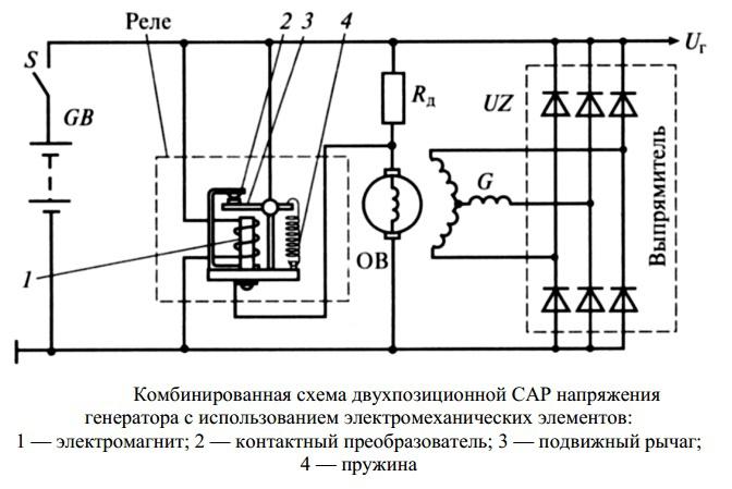
The two-level automatic control system consists of a generator, a rectifier element, and a storage battery. It is based on an electric magnet, its winding is connected to the sensor. The drivers in these types of mechanisms are very simple. These are ordinary springs. A small lever is used as a comparison device. It is mobile and makes commutation. The contact group is the executive device. The regulator is a constant resistance. Such a generator voltage regulator relay, the circuit of which is given in the article, is very often used in technology, although it is morally outdated.
Two-level regulator operation
When the generator is operating, a voltage appears at the output, which is supplied to the winding of the electromagnetic relay. In this case, a magnetic field arises, with its help the lever arm is attracted. The latter is acted upon by a spring, it is used as a comparison device. If the voltage becomes higher than it should be, the contacts of the electromagnetic relay open. In this case, a constant resistance is included in the circuit. A lower current is supplied to the field winding. The voltage regulator relay of the VAZ 21099 generator and other cars of domestic and foreign production works according to a similar principle. If the voltage at the output decreases, then the contacts are closed, while the current strength changes upward.
Electronic regulator
Two-level mechanical voltage regulators have a big drawback - excessive wear of the elements. For this reason, instead of an electromagnetic relay, they began to use semiconductor elements operating in a key mode. The principle of operation is the same, only mechanical elements are replaced by electronic ones. The sensing element is made on which consists of permanent resistors. A Zener diode is used as a master.
The modern relay-voltage regulator of the VAZ 21099 generator is a more advanced device, reliable and durable. The transistors are used by the executive part of the control device. As the voltage at the generator output changes, the electronic key closes or opens the circuit, if necessary, connect an additional resistance. It's worth noting that the two-level regulators are imperfect devices. It is better to use more modern developments instead.

Three-level regulation system
The quality of regulation of such designs is much higher than that of those considered earlier. Previously, mechanical designs were used, but non-contact devices are more common today. All elements used in this system are the same as those discussed above. But the principle of operation is slightly different. First, voltage is applied through a divider to a special circuit in which information is processed. Installing such a generator voltage regulator relay (Ford Sierra can also be equipped with similar equipment) is permissible on any car, if you know the device and wiring diagram.
This is where the actual value is compared with the minimum and maximum values. If the voltage deviates from the value that is set, then a certain signal appears. It is called the mismatch signal. With its help, the current flowing to the excitation winding is regulated. The difference from a two-level system is that there are several additional resistances.

Modern voltage regulation systems
If the voltage regulator relay of the Chinese scooter generator is two-level, then more advanced devices are used on expensive cars. Multilevel control systems can contain 3, 4, 5 or more additional resistances. There are also automatic control tracking systems. In some designs, you can refuse to use additional resistances.
Instead, the response frequency is increased. electronic key... It is simply impossible to use circuits with an electromagnetic relay in servo control systems. One of the latest developments is multilevel system control that uses frequency modulation. In such designs, additional resistances are required, which serve to control the logic elements.
How to remove the relay regulator
It is quite simple to remove the generator voltage regulator relay ("Lanos" or the domestic "nine" you have - it does not matter). It is worth noting that when replacing the voltage regulator, you only need one tool - a flat or Phillips screwdriver. It is not necessary to remove the generator or belt and its drive. Most of the devices are located on the back cover of the generator, and are combined into a single unit with a brush mechanism. The most common breakdowns occur in several cases.
First, for complete erasure graphite brushes. Secondly, upon breakdown of a semiconductor element. How to check the regulator will be described below. When removing, you will need to disconnect the battery. Disconnect the wire that connects the voltage regulator to the generator output. By unscrewing both mounting bolts, you can pull out the device body. But the voltage regulator relay has an outdated design - it is mounted in the engine compartment, separately from the brush assembly.

Device check
The relay-voltage regulator of the VAZ 2106 generator is checked, "kopecks", foreign cars are the same. Once removed, look at the brushes - they should be over 5 millimeters long. If this parameter is different, you need to replace the device. To carry out diagnostics, a constant voltage source is required. It is desirable to be able to change the output characteristic. You can use a battery and a pair as a power source finger batteries... You also need a lamp, it must work from 12 volts. A voltmeter can be used instead. Connect the plus from the power supply to the voltage regulator connector.

Accordingly, connect the negative contact to the common plate of the device. Connect a light bulb or voltmeter with brushes. In this state, a voltage should be present between the brushes if 12-13 volts are supplied to the input. But if you apply more than 15 volts to the input, there should be no voltage between the brushes. This is a sign that the device is working properly. And it does not matter at all whether the voltage regulator relay of the VAZ 2107 generator or another car is diagnosed. If the control lamp is on at any voltage value or does not light up at all, then there is a malfunction of the unit.
conclusions
In the electrical system of the car, the voltage regulator relay of the Bosch generator (as, indeed, of any other company) plays a very important role. Monitor its condition as often as possible, check for damage and defects. Failures of such a device are not uncommon. This will drain the battery at best. And at worst, the supply voltage in the on-board network may increase. This will lead to the failure of most of the electricity consumers. In addition, the generator itself may fail. And its repair will cost a tidy sum, and if you consider that the battery will fail very quickly, the costs are quite cosmic. It is also worth noting that the Bosch generator voltage regulator relay is one of the leaders in sales. It has high reliability and durability, and the characteristics are as stable as possible.
Content:
Voltage is actually electricity. It exists as a primordial force, the effect of which on any objects entails consequences due to their properties. Therefore, the ability to control voltage, its magnitude means to influence the course of many processes in electrical circuits... And this is the most important thing in applied electrical engineering. Next, we'll talk about how to control electricity using a thyristor.
Such different voltages
Voltage can have different properties. Therefore, even the laws describing certain phenomena associated with electricity are limited in application. For example, Ohm's law for a chain section. And there are many such examples. Therefore, when stipulating the properties of an electric regulator, it is necessary to indicate exactly what voltage is meant.In general, two main varieties of it are considered - constant and variable.
They are like the beginning and end of a certain interval, within which impulse signals are located in a huge variety. And earlier, and now, and, most likely, in the future, only one element can regulate the value of all of them - a resistor. That is, an adjustable resistor is a rheostat. It always provides the same effect, regardless of the type of voltage. And at any time. And the moment in time in relation to an alternating or impulse signal is the basis of its definition.
What voltage does the thyristor regulate?
Indeed, depending on it, the magnitude of the voltage changes. The resistor can be driven by the signal at any time. But such a result cannot be obtained by a thyristor, because it is a key. He has only two states:
- with minimal resistance when the key is closed;
- with maximum resistance when the switch is open.
Therefore, the thyristor for the instantaneous voltage value cannot be considered as its regulator. Only within a sufficiently long time interval, at which many instantaneous signal values \u200b\u200bare taken into account, the thyristor can be considered as a voltage regulator. Since such a value is referred to as the effective value, it would be correct to clarify the definition of the regulator as
- thyristor regulator of effective voltage.
How to connect key and load
The most attractive characteristic of thyristors from the very beginning of their appearance was the resistance to high currents. As a consequence, these semiconductor devices have found wide application in a variety of powerful devices. However, in any case, when an electrical regulator is considered, there is an electrical circuit with a load. Equivalently, the load is represented as a resistor with some impedance.
In order for the voltage across this resistor to change, additional elements are needed that are connected to it either in series or in parallel. The first thyristors were non-latching. They could be opened (turned on) at any time. But to turn it off, it was necessary to reduce the current strength to a certain minimum value. For this reason, non-latching thyristors are used to this day only in electrical circuits of alternating or rectified current.
They were also used on constant voltage, but very limited. For example, in the first flash units with controlled light intensity. The light of the flash lamp, which, by controlling the thyristor, forms the necessary illumination of the object, gives a visual representation of the thyristor as an electric regulator for the lamp - load. Energy for this was provided by a capacitor, which was discharged through a special lamp. And in this case, the flash of the greatest strength was obtained.

But in order for the lamp to give less light, a thyristor was turned on in parallel with it. The lamp turned on and illuminated the object. And a special optical sensor with a control circuit monitored its characteristics. And at the right moment he turned on the thyristor. He shunted the lamp, which turned off at the speed of the thyristor. At the same time, part of the capacitor's energy simply disappeared in the form of heat, without bringing any benefit. But at that time it could not be otherwise - there were no lockable thyristors yet.
Types of thyristors and differences in circuits for their use
The thyristor was turned off, since the charging current of the capacitor was selected with this in mind. Of course, a circuit with a series connection of a thyristor and a load is much more efficient. And it is widely used. All dimmers that are used to control lighting and electrical appliances work according to this scheme. But there can be significant differences in them due to the type of thyristor used. A circuit with a symmetrical thyristor, which is operable on alternating voltage when directly connected to the load, turns out to be simpler.

But if we compare symmetric thyristors with ordinary ones that pass current in one direction, immediately noticeably wider the lineup the latter. In addition, their limiting electrical parameters are much higher. But at the same time, a rectifier is required. If a 220 V network is regulated, a rectifier bridge is needed, in which 4 powerful diodes are needed. But every semiconductor device, regardless of whether it is a transistor, thyristor or diode, is characterized by a residual voltage.

It changes little in accordance with the strength of the current flowing through it. And in doing so, heat dissipates on each of the semiconductor devices. If the currents reach units of amperes, the thermal power will be units of watts. Cooling radiators will be required. And this is a deterioration in design indicators. Therefore, triac controllers are more compact and economical. To abandon the rectifier bridge, a circuit of two identical thyristors connected in parallel and opposite is used.

This is definitely a more economical solution for losses. However, the keys must have adequate reverse voltage limits. And this significantly limits the number of their models suitable for this scheme. In addition, it is more difficult to obtain symmetrical half-waves by controlling two switches than with one thyristor. But with a large current, which in industrial installations can be hundreds of amperes or more on a switched-on thyristor, a power of hundreds of watts is dissipated. Dynamic losses warm up the keys even more.
For this reason, reducing the number of semiconductor devices in high-power electrical controllers is a major challenge. The following images show industrial thyristor voltage regulators. In the modern assortment of thyristors among the mass-produced models, there are lockable keys. They can be used in DC circuits.


Therefore, the problems of voltage regulation in thousands of volts at powers, the value of which is measured in megawatts, today are successfully solved different models thyristors.


