A shield is an add-on board. I suggest dividing the shields into full size and standalone modules. Full-sized ones follow the shape of the Arduino board, whether it is UNO, Nano or MEGA. Individual modules are free-form boards designed to perform a specific set of functions. Both of them can be both universal and for performing narrowly focused tasks.
You can find a great many shields in stores, and with a certain qualification, you yourself can breed a printed circuit board that repeats the Arduino in shape and layout of the pins and assemble your own unique one. The picture shows with a set of shields.
Let's start with the shield, which does not carry any special functions, but was created for the convenience of mounting your projects. So, the first one in our review will facilitate the installation of projects with the Arduino Nano board, although the small size of “NANO” is of no use in this case.
On the board there is a connector for connecting a plug from the power supply unit, a voltage stabilizer, as well as terminal blocks. They are signed and correspond to the conclusions of Nanki. In addition, there is a "reset" button and a "Power" LED.

The second shield is for the Uno board. It contains a solderless breadboard for assembling the project and conclusions that duplicate those on the arduino itself - a convenient solution.

Any analog sensor needs power and a negative contact, when there are a lot of them - there are so many jumpers that it will be very difficult to figure out the circuit. Therefore, the designers came up with shields for such solutions. All inputs and outputs are displayed in them, and the supply contacts are duplicated and placed side by side.
Here is an example of such a board for Arduino Mega version.

Wired and wireless
Using these boards, you can manage the microcontroller over a network via an Ethernet cable, for example, or wirelessly via a GSM connection by inserting a SIM card.

This board is called w5100 - contains an Ethernet module and an SD card reader module. This means that you can store data, such as a log of sensor measurements on a memory card, and control the system via a web interface. To connect the arduino to it, use the libraries:
Ethernet library;
Pay attention outwardly, it repeats the concept of Arduino UNO R3, in addition, it will fit on Mega.
If the W5100 seems too big for you, then the ENC28J60 will take up less space. Unfortunately, it no longer has an SD module.

The downside is that it cannot be mounted on a board, but is made as a separate module.
The W5500 is another Ethernet shield option. At its core, this is a modified version of the W5100, optimized in terms of speed and energy efficiency.

Please note that on full-size shields, all pins are duplicated by a terminal block. Unfortunately, shields use ports. This particular one uses MOSI, MISO, SCK, and pin 10 for the CS (Communication Destination Select) signal.
If you need a wireless connection, your choice is Wi-fi shields, if you have an Internet connection and a router, and if you don't have this, then GSM modules or GPRS Shields.

Pictured is the official shield. It has a slot for a Micro SD memory card, and it communicates with the microcontroller via SPI protocols; you can update its software via Mini-USB. Supports 802.11b/g.

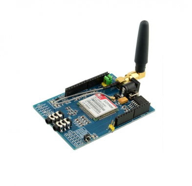
You can see the GPRS shield from Amperka above. You can replace the antenna with a more powerful one. Closer to the viewer is a slot for a SIM card, a little further a slot for a CR1225 battery. The battery on the board is needed for hot real-time clock, and this is an important addition to the capabilities of the GPRS shield. You can send SMS to and from it.
With this board, you can control and give commands (or to any other project of your implementation) from any distance. It is important that you are in a cellular reception area.
How to store data on Arduino?
In projects, not all information is placed in the memory of the microcontroller. Sometimes you need to store some amount of information. The first thing that comes to mind has already been said - this is the recording of information from sensors in order to further study how the environment changes over the course of hours, days, years. A great example is a home weather station. It is useful not only to research scientists, but also to amateurs for general education and development.

It's not a shield, but a module. It is miniature and easy to repeat, by the way, here is its scheme.

There is also a full-size data storage shield. It works with SD-memory cards, there is a real-time clock module on board, which is powered by a 3V CR1220 battery, which is a nice bonus.

We control a powerful load from the microcontroller
The first thing that comes to mind is the relay. With their help, you can switch both DC circuits, and they will cope with a 220-volt household electrical network with a bang.
Specifically, the module that is shown below can switch 1 kW 220 V load (or 5A) for each of the channels, to increase power, you can either parallel several channels, or turn on this relay. In this case, the relays from the shield will play the role of intermediate amplifiers.

Of course, you can switch the relay as I described in the article, through a transistor and you need to select a relay for current, but using a ready-made board will be more reliable, more convenient and looks better.
The relay has one drawback - a limited number of operations - this is a consequence of the burnout of the contacts. This happens due to the occurrence of an arc, when a powerful load is opened (especially of an inductive nature - this is a motor, etc.). You can make such a shield as follows:

And here's what it looks like assembled:

Therefore, thyristors and triacs can be used to turn on the AC load. One problem is that you can’t connect them directly to the arduino, if the pn-junction of the control electrode breaks down, 220 V can be on the microcontroller board and burn it. The way out of this situation is to use an optosimistor.
Since this task often confronts inventors, a ready-made solution was developed - a triac shield, its full name is ICStation 8 Channel EL Escudo Dos Shield for Arduino. It was originally intended to control the glow of "flexible neon".

It has 8 channels to which AC mains and load are connected.
Shields for motors
Driving an electric motor is not always an easy process. In some situations, you may not have enough pins to complete the task, or the control algorithm is quite complicated. With such boards, you will overcome your robot project much faster.
Motor-SHIELD for arduino can control DC motors (4 pieces) or two stepper motors.

It is built on the basis of two L293. This microcircuit is an assembly of two H bridges, this allows you to control with the possibility of reverse two DC motors, or 1 step bipolar motor. Connection diagrams respectively:

And in the upper left corner of the board there are two pads for servos (plus, minus and a control signal). The red circle marks the place where the jumper is installed. If it is, then this board is powered by the Arduino base board, and if not, from an external 5 V source.

Using this module from a domestic manufacturer, you can control two DC motors, it also has a jumper that connects the power lines of the microcontroller or disconnects them - for power from a separate source.

You can control motors that are designed for a voltage range from 5 to 24 volts. Instead of 2 DC motors, you can use 1 single-phase stepper or parallel channels and connect 1 powerful DC motor with a current of up to 4A, and this is not a little - 48 W at a supply voltage of 24 V.
To connect a servo, you need three wires - plus, minus and signal, but what if you have a lot of servos? Your board will turn into a mess of jumpers. To avoid this, there is a Multiservo shield.
Here, too, there is the possibility of separating power circuits, as was the case in the previous version. In total, 18 servos can be connected (numbered from 0 to 17 on the board).

Everywhere has its own specifics, shields for unusual tasks...
Atmega328, the heart of our board, has an ADC. The main problem is that on the arduino uno board we see only 6 analog inputs. What if we have more analog sensors?
You can combine two arduinos into a single network. Use one as the main one, and the second as an auxiliary one for changes, and from the first one send measurement signals to the server or display them on the screen ... But this is difficult: you need to waste memory on additional lines of program code to implement such a system.
What if we multiply each input by 16? In total we can have up to 16*6=96 analog inputs. This is real with a multiplexer. It simply switches 16 analog channels in turn to one analog output, which you connect to the same input of any worldcontroller.

By means of the Atmega microcontroller, it is very difficult to release the voice recognition function, but arduinists need not despair, there is a special solution - EasyVR Shield 3.0.
This is a ready-made, but expensive solution, at the time of writing it costs almost $100 in Russia. First, the shield will write down your command, then compare it with what is written in memory, determining the number - it will execute it.
You can arrange a "dialogue with the computer", it can reproduce what is recorded in it. Without additional amplifiers, it is recommended to “communicate” with this board from a distance of no more than 60 cm.

Displaying the image
LCD Keypad shield is a real control panel. It contains the LCD1602 display (16 characters in two lines), and a set of buttons. Because of them, quite a lot of ports are involved, for example A0 and from D4 to D7 for the keyboard, and port D10 is a PWM backlight brightness control. D8 and D9 - reset and enable.

In fact, there are many displays compatible with arduino. Or rather, those about which the most information has been written and you can easily run them on your system. The display from NOKIA 5110 is quite popular in DIY circles, there are both OLED and TFT screens that work via I2C. But they are not in the "shield" version.

Autonomous power supply
Quite an unusual shield in this collection that performs a common task. Power shield - this is with all the necessary protections and a charging connector. It doesn't sound like much, but it will give your project a finished look, and the power circuits won't have to be placed next to the main boards.

Conclusion
Using shields for all project tasks will avoid unnecessary jumpers and connections, and this will reduce the number of errors and unnecessary jumpers. After assembly, you will receive a multi-story prefabricated board sandwich. This approach is sometimes referred to as "modular design". Among other things, this will facilitate the maintenance, repair and adjustment of equipment.
Enthusiasts practice designing, wiring and assembling unique modules. This is one of the reasons for the high popularity of Arduino not just as a platform for DIY, layouts and prototypes, but also as a platform for ready-made solutions.
01 02.2017
Arduino shields are full of their diversity and functionality. Additional boards expand the capabilities of the main controller. These boards allow you to provide features that are needed for certain tasks in specific projects. There are plenty of them on the market. Let's look at the most popular and interesting modules for practical applications in device development.
From this article you will learn:
Greetings dear visitor! My name is Gridin Semyon, I am the author of the kip-world blog, you can read about me. The market is replete with a variety of different boards, including clones. Today in this article I have highlighted the modules that, in my opinion, are the main ones and are of the greatest interest. I will describe their main functions and work with them in the following series of articles. I relatively divided the shields into several groups:
- Communication;
- Power;
- Sensors-sensors;
- Modems;
- Special.
Communication modules allow you to provide various methods of communication between devices, both wired and wireless. The boards expand the functionality in particular and the system as a whole. This group includes various WI-FI, Ethernet, various interfaces, creating system flexibility.
Power modules - motor drivers, stepper drivers, servo drives. Relay and transistor shields can also be attributed to power ones.
The system can see, hear and feel only through sensors. There are enough of them. Among the large number of sensors, there are exotics - a smoke sensor, a soil moisture sensor, an infrared sensor. And, thanks to the creators of Arduino, the price is very affordable. Since I work in the field of automation, these same sensors will cost 200-300 times more.
To the group modems I took the GPRS modems. They work with GSM connection. The modules perform a very specific function - collecting data, sending SMS, receiving calls.
Category special there are those that are difficult to identify to any group. Developers produce a bunch of all sorts of adapters, remotes, touch panels, LCD indicators. A special RFID key can also be attributed to this group.
If something is missing from the list, write in the comments, I will supplement. For those who contact Arduino for the first time, I suggest reading about. And now I will talk about 5 modules that I would like to get acquainted with first of all, and I offer them to you!!
Internet module Ethernet shield W5100
The first thing I will pay attention to is the Ethernet shield W5100. Internet adapter module for displaying the so-called "visualization" in the browser. Ideal for a smart home system, weather station, dispatching (if you need to monitor physical parameters). There is a possibility of using cloud technologies.

Module description:
- TCP/IP protocol support
- microSD card slot
- Voltage level 3.3/5V
- Compatible with Arduino UNO and MEGA boards
- System levels: UDP, TCP, IPv4, ARP, MAC
GPRS modem GSM shield SIM900
Next on the list is the GSM shield SIM900 expansion board. If the device is far away from you and wireless communication is required, then GSM communication technology is for you. It is possible to send SMS in case of an accident or some event. It can be used for example in a greenhouse for periodic control of temperature and humidity.
Expansion board specifications:
- Assembly based on the SIM900 chip
- Operating frequency GSM 850/900/1800/1900 MHz
- Management with AT commands
- built-in TCP/UDP protocol
- the ability to connect a speaker and headphones, it is possible to send DTMF signals and play recordings as on an answering machine
- SIM card holder and GSM antenna
- 12 GPIO (General Purpose Input/Output), 2 PWM (Pulse Width Modulation) and ADC (Analog to Digital Converter)
There are also expensive analogues for more serious and reliable systems. Most recently, I wrote a program for the interaction of the PM-01 GPRS modem and PLC100. In the event of an accident, the device sends an SMS to the recipient's number.

WIFI module ESP8266
Another way to transfer information wirelessly is WI-FI transmission. For such a case, there is a small WI-FI ESP8266 module. We will consider the connection method and the principle of operation later. She looks like this.

Module description:
- Wireless interface: Wi-Fi 802.11 b/g/n 2.4 GHz
- Modes: P2P (client), soft-AP (access point)
- Maximum output power: 19.5 dB mW (89 mW)
- Rated voltage: 3.3V
- Free I/O ports: 2
- Processor frequency: 80 MHz
Motor driver L293D
To control various cars and tanks on DC motors, the L293D motor driver is mainly used. There are several connection options - for both stepper motors and servo drives. It all depends on the program you write. Write in the comments how you use this driver? In the near future I want to purchase this device, it is very interesting to assemble a robot on wheels. Yes, by the way, here he is:

Its characteristics:
- Compatible with Arduino Mega 1280 and 2560, UNO, Duemilanove, Diecimila
- 4 channel control
- motor power supply from 4.5V to 36V
- allowable load current 600mA per channel, peak current - 1.2A
- overheat protection
- 2 interfaces with an accurate Arduino timer (there will be no “jitter”) for connecting servos to a voltage of 5V, if the supply voltage is needed higher, then the power connection must be redone as described below
- it is possible to simultaneously control 4 bidirectional DC brushed motors or 2 stepper motors and 2 servo motors
- connector for connecting an external source for separate power supply of the control logic and motors
RS-485 interface module
For me personally, this thing is also interesting - RS485 Shield. Why? The RS-485 interface is an industrial twisted pair cable for connecting various industrial modules. The bus works with ModBUS RTU and ModBUS ASCII protocol. Just wondering how Arduino will interact with other devices via the interface.

Module characteristics:
- Power supply 5.0 V
- 16 digital I/O port (including I2C interface)
- 6 analog I/O ports
- Switch to programming mode
- Auto/Manual Transceiver Mode Switch
- Standard RS485 interface, mini RS485 interface (PH2.0) and RS485 pins
Well, that's all, with these modules I would like to work the most. What can you suggest? What can be added to the list? Write in the comments...
In the next article I will tell you how you can connect to Arduino, do not miss it, it will be interesting... Subscribe to updates!
Sincerely, Gridin Semyon.
I had an Arduino Uno lying around for a while. And here is a use for it. I made a convenient shield for flashing running controllers in different cases. Now this debug board is actively used. The shield allows you to flash quite a few controllers from ATMEL, which are still popular among DIYers in many ways. So, under the cut, the manufacture of a shield for flashing Atmega8 (168/328), Attiny13 (45/85) microcontrollers, both in DIP packages and in QFP and SOIC, using adapters.
I gave a link to a similar Arduini Uno debug board, because I don’t remember where I got mine. My scarf with an original cut (of course, this is a copy - because I took it in China): 

Actually, there have already been a lot of reviews on this board, so let's go straight to the shield.
The shield scheme is quite simple: 
Capacitor C4 allows you not to reboot the Arduino Uno itself during the firmware, without it this happens and you can’t flash it. The diagram shows two connectors for connecting controllers in dip28 and dip8 cases. For dip28, quartz is provided with capacitors C2 and C3. The board also has a standard ICSP connector for connecting, for example, your own boards and their firmware. As in typical use, Arduino pin 10 is connected to the RESET of the programmable controllers. Conclusions 11, 12,13 representing ICSP are connected to similar ones on connected microcontrollers. The pluggable controllers are powered and grounded by the Arduino Uno. Indicator LEDs are connected to the Arduino 7,8,9 pins through current-limiting resistors of 1KΩ. Our shield will allow you to flash popular controllers: Atmega8 (168/328), Attiny13 (45/85), both in DIP packages and in QFP and SOIC using adapters.
The dress looks like this: 

Those interested can download, in the format for Sprint Layout. You can also download ready-made for order in China (or local production).
The board shows two versions of holes for dip28 in a narrow and wide package, this is done to connect the QFP32 adapter to the DIP28, which I reviewed. In addition, if you solder a connector for a narrow version of the controller, then you can solder pin lines into the holes for the wide version and immediately test the firmware controller. For dip8, I also provided, in addition to the adapter, holes for the pins. There are also two versions of ICSP connectors - wide (10 pins) and narrow (6 pins), well, and all the other details that are present on the diagram. I used SMD 1206 LEDs, resistors and capacitors (22pF). I distributed the LEDs as follows: Green - READY, Red - ERROR, Yellow - PROG. I also provided pins for additional power and ground, which may be required when testing the controller being flashed.
I ordered the boards in, most likely I would have made them with LUT, but this service allows panelization, and I just found a suitable place on the board in the order, and there was no particular hurry. The factory board still looks much better. This is how they look: 

We solder the parts, I made 2 versions, for a wide dip28: 

Here I did not solder the pins and connectors, as I plan to use this board for flashing controllers using adapters in SOIC and QFP packages.
For narrow dip28: 

As you can see from the photo, I used collet connectors to connect microcircuits in dip cases, I like them more.
QFP32 to DIP28 adapter for connecting to a wide version of the shield: 
Fits great: 
The whole sandwich, including the Arduino Uno: 

For narrow version with ATtiny85 controller inserted: 
To flash controllers in a SOIC8 package, I also use an adapter: 
In order for our design to become a programmer, you should upload the ArduinoISP firmware, which comes with any version, to the Arduino Uno without a shield: 
With such a shield, it became very convenient and fast to flash and test controllers in various cases without fear of breaking connections, like here: 
An example of downloading a program for flashing a diode using a shield and checking its operation on the spot:
I end with this. Thanks to everyone who read to the end! I hope that the information provided will be useful to someone. All with a strange holiday: Old New Year! I plan to buy +22 Add to favorites Liked the review +81 +123
As a rule, acquaintance with the Arduino hardware platform begins with connecting the simplest peripherals: LEDs, buttons, buzzers, etc. Typically, circuits for this are assembled on a breadboard, but another option is possible. On sale there is a shield on which the most widespread simple peripherals are already arranged. This multifunctional shield was purchased on Ali for $2.

The device comes in an antistatic bag. The module has dimensions of 69 x 53 x 20 mm, weight 24.4 g.

The device is designed to work with the Arduino UNO, Arduino Leonardo and Arduino Mega boards, although, of course, using wires, you can connect this device to any board of the Arduino family. However, the latter does not seem rational to the author of this review, since in this case the main advantage of this board is lost - ease of installation.

It should be noted that when installing this board on top of the classic Arduino UNO, the board rises with a slight skew, the reason for this is the rather large USB-BF connector on the Arduino UNO board. Of course, there will be no such problem on the Arduino Leonardo board. However, this did not affect the operation of this shield in any way.


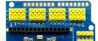
The board has 4 seven-segment indicators connected via shift registers 74HC595, next to which there is a reset button and an APC220 connector for connecting Bluetooth modules or a voice module.

In addition, the board has four red LEDs connected to ports D10, D11, D12, D13 of the Arduino board. The buzzer is connected to the D3 port, it should be noted that the sound emitter is equipped with a built-in generator, so it will not work to play a simple melody with it. At the bottom of the board is a trimmer connected to port A0.
Three buttons connected to ports A1, A2, A3 (digital ports D15, D16, D17, respectively). Four three-pin connectors are connected to ports D5, D6, D9, A5 and are intended for connecting external devices. The list of devices is completed by a connector for connecting analog LM35 or digital DS18B20 temperature sensors. Sensors are connected to port A4. Jumper J1 connects or disconnects the 10 kΩ resistor for the correct operation of the sensors
Controlling LEDs and a sound emitter is no different from controlling any simple digital device. For example, you can blink the LEDs and sound the buzzer using the port_D program.

Working with a potentiometer can also be described by the classic example of AnalogInput , which, using a variable resistor, controls the blinking frequency of the LED connected to the D13 port.

You can try to control the LEDs using the buttons, for this you need to download the program _3_LED_with_button
Seven-segment indicators are a powerful visualization tool, it should be borne in mind that if they are not used, then random characters are displayed on them.

You can check their performance using the program _7seg

In principle, based on this shield, without any hardware modifications, you can assemble a variety of timers, for example, a countdown timer Count_Down_Timer . The timer allows you to set time intervals from 10 seconds to 60 minutes 50 seconds in increments of 10 seconds. In this timer, press A2 to set the minutes, press A3 to set the seconds, and press A1 to start the countdown. At the end of the set period of time, an audible signal sounds.

In general, the shield leaves a favorable impression. This device not only allows you to get acquainted with the basic Arduino, but also can become the basis for a simple project, such as a timer, event counter, etc. Naturally, the downside of an attempt to put a maximum of peripherals on the shield is that in each specific project some of the device details will not be used.
It may seem that such a primitive periphery will be relevant only for learning at the initial stage. This is partly true. Of course, problems with connecting several buttons, LEDs, a buzzer or a seven-segment indicator to the Arduino board can only occur for a person who has a You. Any more or less experienced radio amateur is unlikely to have problems with this.
Here the question is different, if the goal is to create a prototype device in the minimum time, then extra trivial operations are exactly what actually distracts from creativity. In fact, this shield fits into the ideology of buying amenities and your own free time for money.
useful links
- http://radioskot.ru/blog/raspinovka_usb_i_micro_usb/2013-09-11-97
- http://publicatorbar.ru/2017/12/21/arduino-multi-function-shield/
- http://robocraft.ru/blog/arduino/59.html
- https://www.youtube.com/watch?v=_z263RK31QA
The review was prepared by Denev.