In this article, we will look at the principles of operation of optical mouse sensors, shed light on the history of their technological development, and also debunk some myths associated with optical "rodents".
Who made you...
Optical mice familiar to us today trace their pedigree since 1999, when the first copies of such manipulators from Microsoft appeared on mass sale, and after a while from other manufacturers. Before the advent of these mice, and for a long time after that, most mass-produced computer "rodents" were optomechanical (the movements of the manipulator were tracked by an optical system associated with the mechanical part - two rollers responsible for tracking the movement of the mouse along the x and y axes; these rollers, in in turn, rotated from the ball rolling when the user moved the mouse). Although there were also purely optical models of mice that required a special rug for their work. However, such devices were not often encountered, and the very idea of development of such manipulators gradually came to naught.
The “view” of mass optical mice familiar to us today, based on the general principles of operation, was “bred” in the research laboratories of the world famous corporation Hewlett-Packard. More precisely, in its division of Agilent Technologies, which only relatively recently completely separated into a separate company in the structure of HP Corporation. To date, Agilent Technologies, Inc. - a monopolist in the market of optical sensors for mice, no other companies develop such sensors, no matter what anyone tells you about the exclusive IntelliEye or MX Optical Engine technologies. However, the enterprising Chinese have already learned how to “clone” Agilent Technologies sensors, so when buying an inexpensive optical mouse, you may well become the owner of a “left” sensor.
Where the visible differences in the operation of manipulators come from, we will find out a little later, but for now, let's start considering the basic principles of the operation of optical mice, or rather their movement tracking systems.
How do computer mice "see"
In this section, we will study the basic principles of operation of optical motion tracking systems, which are used in modern mouse-type manipulators.
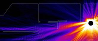
So, the "vision" of the optical computer mouse is due to the following process. With the help of an LED, and a system of lenses focusing its light, a surface area is highlighted under the mouse. The light reflected from this surface, in turn, is collected by another lens and falls on the receiving sensor of the microcircuit - the image processor. This chip, in turn, takes pictures of the surface under the mouse at a high frequency (kHz). Moreover, the microcircuit (let's call it an optical sensor) not only takes pictures, but also processes them itself, since it contains two key parts: the Image Acquisition System (IAS) image acquisition system and an integrated DSP image processing processor.

Based on the analysis of a series of successive images (which are a square matrix of pixels of different brightness), the integrated DSP processor calculates the resulting indicators indicating the direction of mouse movement along the x and y axes, and transmits the results of its work outside via the serial port.
If we look at the block diagram of one of the optical sensors, we will see that the microcircuit consists of several blocks, namely:

- the main block is, of course, ImageProcessor- image processor (DSP) with built-in light signal receiver (IAS);
- Voltage Regulator And Power Control- a voltage adjustment and power consumption control unit (power is supplied to this unit and an additional external voltage filter is connected to it);
- Oscillator- an external signal is supplied to this block of the chip from a master crystal oscillator, the frequency of the incoming signal is about a couple of tens of MHz;
- Led Control- this is a LED control unit, with which the surface under the mouse is highlighted;
- Serial port- a block that transmits data about the direction of mouse movement outside the chip.
We will consider some details of the operation of the optical sensor chip a little later, when we get to the most advanced of modern sensors, but for now let's return to the basic principles of operation of optical systems for tracking the movement of manipulators.
It should be clarified that the optical sensor chip does not transmit information about mouse movement directly to the computer via the Serial Port. Data is sent to another controller chip installed in the mouse. This second "master" chip in the device is responsible for responding to mouse clicks, scroll wheel rotation, etc. This chip, among other things, already directly transmits information about the direction of mouse movement to the PC, converting the data coming from the optical sensor into signals transmitted via PS / 2 or USB interfaces. And already the computer, using the mouse driver, based on the information received via these interfaces, moves the cursor-pointer across the monitor screen.
It is precisely because of the presence of this “second” controller microcircuit, more precisely, due to the different types of such microcircuits, that the first models of optical mice differed quite noticeably among themselves. If I can’t speak too badly about expensive devices from Microsoft and Logitech (although they were not at all “sinless”), then the mass of inexpensive manipulators that appeared after them did not behave quite adequately. When moving these mice on ordinary rugs, the cursors on the screen made strange somersaults, jumped almost to the floor of the desktop, and sometimes ... sometimes they even went on an independent journey across the screen when the user did not touch the mouse at all. It even got to the point that the mouse could easily bring the computer out of standby mode, erroneously registering the movement, when no one actually touched the manipulator.

By the way, if you are still struggling with a similar problem, then it is solved in one fell swoop like this: select My Computer\u003e Properties\u003e Hardware\u003e Device Manager\u003e select the installed mouse\u003e go to its "Properties"\u003e in the window that appears, go to the tab "Management power supply" and uncheck the box "Allow the device to bring the computer out of standby mode" (Fig. 4). After that, the mouse will no longer be able to wake the computer from standby under any pretext, even if you kick it with your feet :)
So, the reason for such a striking difference in the behavior of optical mice was not at all in the "bad" or "good" installed sensors, as many still think. Believe me, this is nothing more than a myth. Or fantasy, if you prefer :) Mice behaving in completely different ways often had exactly the same optical sensor chips installed (fortunately, there were not so many models of these chips, as we will see below). However, thanks to the imperfect controller chips installed in optical mice, we had the opportunity to strongly scold the first generations of optical rodents.

However, we have digressed somewhat from the topic. We return. In general, the mouse optical tracking system, in addition to the sensor chip, includes several more basic elements. The design includes a holder (Clip) in which an LED is installed and the sensor chip itself (Sensor). This system of elements is mounted on a printed circuit board (PCB), between which and the bottom surface of the mouse (Base Plate) a plastic element (Lens) is fixed, containing two lenses (the purpose of which was described above).

When assembled, the optical tracking element looks like shown above. The scheme of operation of the optics of this system is presented below.

The optimal distance from the Lens element to the reflective surface under the mouse should be between 2.3 and 2.5 mm. These are the sensor manufacturer's recommendations. Here is the first reason why optical mice feel bad “crawling” on plexiglass on the table, all kinds of “translucent” rugs, etc. And you should not glue “thick” legs on optical mice when the old ones fall off or are erased. The mouse, due to excessive “elevation” above the surface, can fall into a state of stupor, when it becomes quite problematic to “stir up” the cursor after the mouse is at rest. These are not theoretical fabrications, this is personal experience :)
By the way, about the problem of durability of optical mice. I remember that some of their manufacturers claimed that, they say, "they will last forever." Yes, the reliability of the optical tracking system is high; it cannot be compared with the optomechanical one. At the same time, there are many purely mechanical elements in optical mice that are subject to wear in the same way as under the dominance of the good old “optomechanics”. For example, the legs of my old optical mouse were worn out and fell off, the scroll wheel broke (twice, the last time irrevocably :(), the wire in the connecting cable frayed, the cover of the case peeled off the manipulator ... but the optical sensor works normally, as if nothing Based on this, we can safely state that rumors about the allegedly impressive durability of optical mice have not been confirmed in practice. And why, pray tell, optical mice "live" for too long? After all, new, more "Perfect models created on a new element base. They are obviously more perfect and more convenient to use. Progress, you know, is a continuous thing. Let's see what it was like in the field of evolution of optical sensors that interest us. Let's see now."
From the history of mouse vision

Development engineers at Agilent Technologies, Inc. they do not eat their bread in vain. Over the past five years, the company's optical sensors have undergone significant technological improvements and their latest models have very impressive characteristics.
But let's talk about everything in order. Chips were the first mass-produced optical sensors. HDNS-2000(Fig. 8). These sensors had a resolution of 400 cpi (counts per inch), that is, dots (pixels) per inch, and were designed for a maximum mouse movement speed of 12 inches / s (about 30 cm / s) with an optical sensor frame rate of 1500 frames in a second. Permissible (while maintaining stable operation of the sensor) acceleration when moving the mouse "in a jerk" for the HDNS-2000 chip is no more than 0.15 g (approximately 1.5 m/s2). 
Then optical sensor chips appeared on the market. ADNS-2610 And ADNS-2620. The optical sensor ADNS-2620 already supported a programmable frequency of "shooting" the surface under the mouse, with a frequency of 1500 or 2300 shots / s. Each picture was taken with a resolution of 18x18 pixels. For the sensor, the maximum operating speed of movement was still limited to 12 inches per second, but the limit on permissible acceleration increased to 0.25 g, with a surface “photographing” frequency of 1500 frames / s. This chip (ADNS-2620) also had only 8 legs, which made it possible to significantly reduce its size compared to the ADNS-2610 chip (16 pins), which looks similar to the HDNS-2000. At Agilent Technologies, Inc. set out to "minimize" their chips, wanting to make the latter more compact, more economical in power consumption, and therefore more convenient for installation in "mobile" and wireless manipulators.
The ADNS-2610 microcircuit, although it was a “large” analogue of the 2620, was deprived of support for the “advanced” mode of 2300 shots / s. In addition, this option required 5V power, while the ADNS-2620 chip cost only 3.3V.
Chip coming soon ADNS-2051 was a much more powerful solution than the HDNS-2000 or ADNS-2610 chips, although outwardly (packaging) it was also similar to them. This sensor already made it possible to programmatically control the "resolution" of the optical sensor, changing it from 400 to 800 cpi. The variant of the microcircuit also allowed adjusting the frequency of surface shots, and it allowed changing it in a very wide range: 500, 1000,1500, 2000 or 2300 shots/s. But the size of these very pictures was only 16x16 pixels. At 1500 shots/s, the maximum allowable acceleration of the mouse during the "jerk" was still 0.15 g, the maximum possible movement speed was 14 inches/s (i.e., 35.5 cm/s). This chip was designed for a supply voltage of 5 V. 
Sensor ADNS-2030 designed for wireless devices, and therefore had low power consumption, requiring only 3.3 V of power. The chip also supported energy-saving functions, such as the function to reduce power consumption when the mouse is at rest (power conservation mode during times of no movement), switch to sleep mode, including when the mouse is connected via USB interface, etc. The mouse, however, could also work in a non-power-saving mode: the value of "1" in the Sleep bit of one of the chip registers made the sensor "always awake", and the default value of "0" corresponded to the operating mode of the microcircuit, when after one second, if the mouse did not move (more precisely, after receiving 1500 completely identical surface shots), the sensor, along with the mouse, went into power saving mode. As for the other key characteristics of the sensor, they did not differ from those of the ADNS-2051: the same 16-pin package, movement speed up to 14 inches / s with a maximum acceleration of 0.15 g, programmable resolution of 400 and 800 cpi, respectively, snapshot rates could be exactly the same as the above-considered version of the microcircuit.
These were the first optical sensors. Unfortunately, they were characterized by shortcomings. A big problem that occurred when moving an optical mouse over surfaces, especially with a repeating small pattern, was that the image processor sometimes confused separate similar areas of a monochrome image received by the sensor and incorrectly determined the direction of mouse movement.

As a result, the cursor on the screen did not move as required. The pointer on the screen even became capable of impromptu:) - of unpredictable movements in an arbitrary direction. In addition, it is easy to guess that if the mouse was moved too fast, the sensor could generally lose any “link” between several subsequent surface shots. Which gave rise to another problem: the cursor, when moving the mouse too sharply, either twitched in one place, or “supernatural” phenomena occurred in general :) phenomena, for example, with the rapid rotation of the world around in toys. It was quite clear that for the human hand, the limitations of 12-14 inches / s in terms of the maximum speed of moving the mouse are clearly not enough. There was also no doubt that 0.24 s (almost a quarter of a second), allotted for accelerating the mouse from 0 to 35.5 cm / s (14 inches / s - the maximum speed) is a very long period of time, a person is able to move the brush much faster. And therefore, with sharp mouse movements in dynamic gaming applications with an optical manipulator, it can be hard ...
Agilent Technologies also understood this. The developers realized that the characteristics of the sensors needed to be radically improved. In their research, they adhered to a simple but correct axiom: the more pictures per second the sensor takes, the less likely it is that it will lose the “trace” of mouse movement when the computer user makes sudden movements :)
Although, as we can see from the above, optical sensors have evolved, new solutions are constantly being released, however, development in this area can be safely called “very gradual”. By and large, there were no cardinal changes in the properties of the sensors. But technological progress in any field is sometimes characterized by sharp jumps. There was such a “breakthrough” in the field of creating optical sensors for mice. The advent of the ADNS-3060 optical sensor can be considered truly revolutionary!
Best of

Optical sensor ADNS-3060, compared to its "ancestors", has a truly impressive set of characteristics. The use of this chip, packaged in a 20-pin package, provides optical mice with never-before-seen possibilities. The permissible maximum moving speed of the manipulator has increased to 40 inches / s (that is, almost 3 times!), i.e. reached the "sign" speed of 1 m/s. This is already very good - it is unlikely that at least one user moves the mouse at a speed exceeding this limit so often that he constantly feels discomfort from using the optical manipulator, including gaming applications. The allowable acceleration, however, has increased, frighteningly, by a hundred times (!), and has reached a value of 15 g (almost 150 m/s 2). Now the user is given 7 hundredths of a second to accelerate the mouse from 0 to the maximum 1 m / s - I think that now very few will be able to exceed this limitation, and even then, probably in dreams :) The programmable speed of taking surface images with an optical sensor in the new chip model exceeds 6400 fps, i.e. "beats" the previous "record" almost three times. Moreover, the ADNS-3060 chip can itself adjust the image repetition rate to achieve the most optimal operating parameters, depending on the surface over which the mouse moves. The "resolution" of the optical sensor can still be 400 or 800 cpi. Let's use the example of the ADNS-3060 microcircuit to consider the general principles of operation of optical sensor chips.
The general scheme for analyzing mouse movements has not changed compared to earlier models - microimages of the surface under the mouse obtained by the IAS sensor unit are then processed by the DSP (processor) integrated in the same chip, which determines the direction and distance of movement of the manipulator. The DSP calculates the relative x and y offset values relative to the mouse's home position. Then the external mouse controller chip (what we need it for, we said earlier) reads information about the movement of the manipulator from the serial port of the optical sensor chip. Then, this external controller translates the received data on the direction and speed of mouse movement into signals transmitted via standard PS / 2 or USB interfaces, which are already coming from it to the computer.

But let's delve a little deeper into the features of the sensor. The block diagram of the ADNS-3060 chip is presented above. As you can see, its structure has not fundamentally changed compared to its distant "ancestors". 3.3 Power is supplied to the sensor through the Voltage Regulator And Power Control block, the same block is assigned the voltage filtering function, for which connection to an external capacitor is used. The signal coming from the external quartz resonator to the Oscillator unit (the nominal frequency of which is 24 MHz, lower-frequency master oscillators were used for previous microcircuit models) serves to synchronize all computational processes occurring inside the optical sensor microcircuit. For example, the frequency of snapshots of an optical sensor is tied to the frequency of this external generator (by the way, the latter is not subject to very strict restrictions on permissible deviations from the nominal frequency - up to +/- 1 MHz). Depending on the value entered at a certain address (register) of the chip memory, the following operating frequencies for taking pictures by the ADNS-3060 sensor are possible.
| Register value, hexadecimal | Decimal value | Sensor snapshot rate, fps |
| OE7E | 3710 | 6469 |
| 12C0 | 4800 | 5000 |
| 1F40 | 8000 | 3000 |
| 2EE0 | 12000 | 2000 |
| 3E80 | 16000 | 1500 |
| BB80 | 48000 | 500 |
As you might guess, based on the data in the table, the sensor snapshot frequency is determined by a simple formula: Frame rate = (Generator master frequency (24 MHz) / Frame rate register value).
The surface images (frames) taken by the ADNS-3060 sensor have a resolution of 30x30 and represent the same matrix of pixels, the color of each of which is encoded in 8 bits, i.e. one byte (corresponding to 256 shades of gray for each pixel). Thus, each frame (frame) entering the DSP processor is a sequence of 900 bytes of data. But the "cunning" processor does not process these 900 bytes of a frame immediately upon arrival, it waits until 1536 bytes of pixel information are accumulated in the corresponding buffer (memory) (that is, information about another 2/3 of the next frame is added). And only after that, the chip starts to analyze information about the movement of the manipulator by comparing changes in successive surface images.

With a resolution of 400 or 800 pixels per inch, they are indicated in the RES bit of the microcontroller memory registers. A zero value of this bit corresponds to 400 cpi, and a logical one in RES puts the sensor in 800 cpi mode.
After the integrated DSP processor processes the image data, it calculates the relative offset values of the manipulator along the X and Y axes, entering specific data about this into the memory of the ADNS-3060 chip. In turn, the microcircuit of the external controller (mouse) through the Serial Port can "scoop" this information from the memory of the optical sensor with a frequency of about once per millisecond. Note that only an external microcontroller can initiate the transfer of such data, the optical sensor itself will never initiate such a transfer. Therefore, the question of the efficiency (frequency) of tracking the movement of the mouse largely lies on the "shoulders" of the external controller chip. Data from the optical sensor is transmitted in 56-bit packets.
Well, the Led Control block with which the sensor is equipped is responsible for controlling the backlight diode - by changing the value of bit 6 (LED_MODE) at address 0x0a, the optosensor microprocessor can switch the LED to two operating modes: logical "0" corresponds to the state "diode is always on", logical "1" puts the diode in "on only when needed" mode. This is important, say, when working with wireless mice, as it allows you to save the charge of their autonomous power sources. In addition, the diode itself can have several brightness modes.
That, in fact, is all with the basic principles of the optical sensor. What else can be added? The recommended operating temperature of the ADNS-3060 chip, as well as all other chips of this kind, is from 0 0С to +40 0С. Although Agilent Technologies guarantees the preservation of the working properties of its chips in the temperature range from -40 to +85 °С.
Laser future?
Recently, the web was filled with laudatory articles about the Logitech MX1000 Laser Cordless Mouse, which used an infrared laser to illuminate the surface under the mouse. It promised almost a revolution in the field of optical mice. Alas, having personally used this mouse, I was convinced that the revolution did not happen. But it's not about that.
I have not disassembled the Logitech MX1000 mouse (did not have the opportunity), but I am sure that our old friend, the ADNS-3060 sensor, is behind the "new revolutionary laser technology". For, according to the information I have, the characteristics of the sensor of this mouse are no different from those of, say, the Logitech MX510 model. All the "hype" arose around the statement on the Logitech website that using a laser optical tracking system, twenty times (!) More details are revealed than using LED technology. On this basis, even some respected sites have published photographs of certain surfaces, they say, as they see their ordinary LED and laser mice :) 
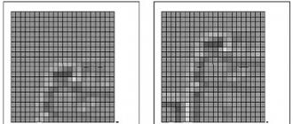
Of course, these photos (and thank you for that) were not the multi-colored bright flowers with which they tried to convince us on the Logitech website of the superiority of the laser illumination of the optical tracking system. No, of course, optical mice did not begin to “see” anything similar to the given color photographs with varying degrees of detail - the sensors still “photograph” no more than a square matrix of gray pixels that differ only in different brightness (processing information about the extended color the palette of pixels would be an exorbitant burden on the DSP).
Let's estimate, to get a 20 times more detailed picture, you need, sorry for the tautology, twenty times more details, which can only be conveyed by additional image pixels, and nothing else. It is known that the Logitech MX 1000 Laser Cordless Mouse takes pictures of 30x30 pixels and has a maximum resolution of 800 cpi. Consequently, there can be no question of any twenty-fold increase in the detailing of images. Where did the dog fumble :), and are such statements generally unfounded? Let's try to figure out what caused the appearance of this kind of information.
As you know, a laser emits a narrowly directed (with a small divergence) beam of light. Therefore, the illumination of the surface under the mouse with a laser is much better than with an LED. The laser operating in the infrared range was chosen, probably in order not to dazzle the eyes by the possible reflection of light from under the mouse in the visible spectrum. The fact that the optical sensor works normally in the infrared range should not be surprising - from the red range of the spectrum, in which most LED optical mice work, to the infrared - "within a stone's throw", and it is unlikely that the transition to a new optical range was difficult for the sensor. For example, the Logitech MediaPlay manipulator uses an LED, but also provides infrared illumination. Current sensors work without problems even with blue light (there are manipulators with such illumination), so the spectrum of the illumination area is not a problem for sensors. So, due to the stronger illumination of the surface under the mouse, we can assume that the difference between places that absorb radiation (dark) and reflect rays (light) will be more significant than when using a conventional LED - i.e. the image will be more contrast.

Indeed, if we look at real images of the surface taken by a conventional LED optical system and a system using a laser, we will see that the "laser" version is much more contrast - the differences between the dark and bright areas of the image are more significant. Of course, this can significantly facilitate the work of the optical sensor and, perhaps, the future belongs to mice with a laser illumination system. But it is hardly possible to call such "laser" images twenty times more detailed. So this is another "newborn" myth.
What will be the optical sensors of the near future? It's hard to say. They will probably switch to laser illumination, and there are already rumors on the Web about a sensor being developed with a “resolution” of 1600 cpi. We can only wait.
The mouse is one of the tools that can be connected to a computer to manipulate the cursor. The cursor, a flickering rectangle of light on the screen, indicates where the operator's next action will be located. When a letter is typed, it appears on the screen at the location marked by the cursor. The cursor control keys allow the operator to move the cursor across the screen, up and down.
But the rotating mouse on the operator's desk (below) can move the cursor around the screen in any direction at the speed of a hand. Buttons on the mouse allow the operator to select options from the OSD or draw lines on the screen.
There are two types of mice - mechanical and optical; any easily fits in the human palm. When a mechanical mouse (right) moves across a surface, its internal mechanism measures the distance, direction of movement, and tells the computer to repeat that movement on the monitor. The optical mouse (bottom left) performs this task using light rays to determine the direction of the mouse on the grid. The joystick (bottom right) serves as a control mechanism in many video games.

Mouse movement and cursor
Connected to the keyboard by electrical wires, the mouse causes the cursor to imitate its movements on the screen at any distance and direction. Therefore, when moving the mouse, the operator must look at the screen. Since the mouse can move in any direction, forming curved and diagonal lines, it is an excellent drawing tool.
How an optical mouse "sees"
The optical mouse is arranged on a special grid. As the mouse moves over the grid, light from the LED, a Light Emitting Diode, enters the grid. The lenses and mirror send beams to a sensor, or photodetector, which marks the coordinates of the lines passed.
How a mechanical mouse works
On the inside of a mechanical mouse, there is a brake ball associated with slotted discs (brown) that rotates as the mouse is moved. An LED on each disk emits light, while a photodiode, on the other hand, counts the pulses of light passing through the slots in the rotating disk. These pulses are converted into cursor movement on the screen.
Inside the joystick
Like a mouse, a joystick detects movements in two directions and coordinates signals. The handle passes through the movable axle (center) and enters the right hand corner of the lever (bottom). Two electronic devices, called variable resistors, send signals that change the position of the axis and lever and make the cursor move.
3.1. How is a mouse made?
3.2. Mouse drivers in MS-DOS
3.3. Mouse service interrupt
3.1. How is a mouse made? Opto-mechanical mice
A mouse is a small box with two or three keys that is connected to a computer with a thin cable:
Rice. 2. The appearance of the mouse
Buttons are located on top of the case. Usually there are two or three. The purpose of these buttons is completely determined by the software. The ball is visible below. It is usually covered with rubber for better grip on the table surface.
Structurally, the mouse is a plastic box of a streamlined shape, which contains:
A flexible cable connects the mouse to the computer system unit.
|
Picture 1 |
Figure 2 |
Figure 3 |
Figure 1 shows the internals of a mouse. The following required components of the mouse are marked in the figure: 1 - Photo emitter 2 - Photo detector 3 - Ball 4 - Rotating roller 5 - Pressure wheel 6 - Button 7 - Cable 8 - Controller (special microcircuit)
The principle of the mouse is as follows.
When a mouse button is pressed, the controller processes this event and sends information about the action taken to the computer.
When moving the mouse over the surface, the ball rotates, and its rotation is transmitted to two mutually perpendicular rotating rollers, which generate signals of movement "left-right", "up-down". Each of the two rotating rollers has a slotted disc. As the roller rotates, the slotted rotating disc passes (see Figure 2) or blocks (see Figure 3) a beam that emits a photoemitter and receives a photodetector. The signal from the photodetector is processed by the controller and sent to the computer. Thus, the mechanical rotation of the mouse ball is converted into an electrical signal of its movement, and the rotation of the rollers is perceived and transmitted to the computer.
The software will associate mouse movements on the table surface with movements, for example, of the cursor on the screen surface. By moving the mouse on the table (and, accordingly, the cursor on the screen), you can specify (select) various objects on the screen.
If you open the case of the mouse, you will see a simple mechanism consisting of a ball, two axles with rubber rollers, two discs with holes and four photo sensors:
Rice. 3. Inside the mouse
When you move the mouse across the table surface, the rotation of the ball is transferred through the rubber rollers to two perforated discs. Photo sensors are located near each disk (two per disk). They fix the direction of rotation and the angle of rotation of the disks. As the mouse moves, the photosensors generate pulses that are transmitted to the computer. The number of these pulses depends linearly on the amount of mouse movement.
Nowadays, computer hardware manufacturers offer a wide range of different types of mice. Mice differ not only in appearance and number of keys, but also in the way they are connected to the computer, the mice may have different accuracy and different software interface.
There are two most commonly used ways to connect a mouse to a computer:
via serial port (COM1, COM2);
through a special adapter that is inserted into the expansion slot of the computer motherboard.
As for the software interface, two types can be distinguished:
3-Button Mouse Systems
Microsoft two-button mouse
Some mice can emulate both types. The emulated type depends on the state of the switch located on the bottom cover of the mouse case, or whether a mouse button was pressed when the computer was powered on.
In this lesson I will talk about the types of computer mice. We will consider ball, optical and laser mice.
Types of computer mice
Computer mouse- This is a device with which you can select any objects on the computer screen and control them.
Connection methods are wired and wireless. They differ from each other primarily in the principle of operation. The most common types are:
- ball-bearing;
- Optical;
- Laser.
Let's take a closer look at each type.
Ball
The outdated and cheapest option is quite large, with a rubberized ball protruding slightly from the base.
With its rotation, it sets a certain direction for two rollers inside, and they transmit them to special sensors, which “turn” the movement of the mouse into moving the cursor on the monitor.

But there is one minus: if the ball gets dirty, the mouse starts to stick. Periodic cleaning is simply necessary for normal operation. In addition, such a mouse requires a certain surface, because the accuracy of work depends on the adhesion of the device to it.
Optical
An optical computer mouse does not have rotating elements - the principle of its operation is qualitatively different from the previous version.

Its design is a small camera that takes up to a thousand pictures per second. When moving, the camera photographs the work surface, illuminating it. The processor processes these "snapshots" and sends a signal to the computer - the cursor moves.

Such a device can work on almost any surface, except for a mirror, and does not need to be cleaned. In addition, such a mouse is smaller and lighter than a ball mouse.
The disadvantage of optical mice is their glow when the computer is turned off. But this problem is solvable: the computer just needs to be disconnected from the voltage line.

By the way, in many modern models this issue is completely easily solved: on the mouse itself there is a special button that turns off the device.
laser
The laser mouse is an advanced version of the optical mouse. The principle of operation is the same, only a laser is used for illumination, not an LED.

Such a refinement made the device almost perfect: the mouse works on any surface (including glass and mirror), it is more reliable, economical and accurate - the cursor movements correspond to the real movement as much as possible.
In addition, even with the computer turned on, it is unlikely to interfere with sleep at night - the laser backlight is very weak.
Wired and wireless
Wired mice are connected to the computer using a special cable (wire).

Wireless do not have a "tail" - they transmit a signal to a computer via radio waves or via Bluetooth. They are connected using a special small receiver (looking very similar to a USB flash drive), which is inserted into the USB connector.

Of the shortcomings, it should be noted that all wireless ones are deprived of stationary power due to the lack of a cable. Therefore, they need to be recharged separately - from batteries and accumulators.

In addition, "tailless" may have malfunctions due to a not always stable connection. Well, it should be noted that at a price they can significantly exceed the "tailed ones".
Computer mouse buttons
Buttons are the main controls. It is with their help that the user performs the main actions: opens objects, selects, moves, and so on. Their number in modern models may vary, but only two buttons and a scroll wheel are enough to work.

It is this version of a computer mouse - two buttons and a wheel - that is most common today.

On a note . Often there are mice where there is a small button near the wheel. Its function is to double-click the left button.

Some modern mice have an additional button on the side, under the thumb. It can be programmed to perform some action: for example, to open a certain program.

Fans of computer games treat it with respect: it allows you to program the choice of weapons, which provides significant time savings in the game.
Manufacturers are constantly inventing something new by adding different buttons, but this does not bring tangible benefits - most users ignore them anyway.
True, there are separate “non-standard” models that are used with pleasure by narrow specialists and gamers. For example, a trackball mouse (with a 2D scroll wheel) or a mini joystick (analogous to a game joystick).

Modern mice
Regular two-button mouse has all the necessary qualities: it allows you to perform a lot of manipulations (clicks, drags and other gestures), easily hits the right pixel on the monitor, is suitable for long-term work and is relatively inexpensive.
Manufacturers are constantly updating the design, trying to make it more ergonomic, that is, as comfortable as possible for the grip. So today a user with any level of requests can choose the optimal model - both in terms of technical characteristics and in terms of comfort.

A few years ago, Apple introduced the touch mouse. There are no buttons in it - the control is carried out using gestures.

Another recent development is the so-called gyro mouse. It recognizes movement not only on the surface, but also in the air - you can control it by waving a brush.

True, such an innovation is far from perfect: the hand gets tired quickly when managing it.
Good afternoon friends!
Today we will talk about one very convenient device that we are so used to and without which we can no longer imagine working on a computer.
What is a "mouse"?
"Mouse" is a button manipulator, designed together with the keyboard to enter information into .
Indeed, he looks like a mouse with a tail. A modern computer is already unthinkable without this contraption.
The "mouse" is much more convenient to use than, for example, the built-in laptop manipulator.
Therefore, users often turn off this laptop “mat” and connect a “mouse”.
How does this handy thing work?
The first designs of manipulators
![]() The first manipulators included a ball that touched two disc rollers.
The first manipulators included a ball that touched two disc rollers.
The outer rim of each disc had perforation. The shafts were located perpendicular to each other.
One shaft was responsible for the X coordinate (horizontal movement), the other for the Y coordinate (vertical movement).
When moving the manipulator on the table, the ball rotated, transferring torque to the shafts.
If the manipulator was moved in the “right-left” direction, then the shaft responsible for the X coordinate rotated mainly. The cursor on the monitor screen also moved to the right-left. If the mouse moved in the direction “toward-away from itself”, the shaft responsible for the Y coordinate rotated mainly. The cursor on the monitor screen moved up and down.
If the manipulator was moved in an arbitrary direction, both shafts rotated, and the cursor moved accordingly.
Optical sensors in old mice
Such devices contained two optical sensors - optocouplers. The optocoupler includes an emitter (LED emitting in the IR range) and a receiver - (photodiode or phototransistor). The emitter and receiver are located at a close distance from each other.
When the manipulator moves, the shafts with discs rigidly fixed to them rotate. The perforated edge of the disc periodically crosses the radiation flux from the emitter to the receiver. As a result, a series of pulses is obtained at the output of the receiver, which is fed to the controller chip. The faster the mouse moves, the faster the shafts will rotate. There will be a higher frequency of pulses, and the cursor will move faster on the monitor screen.
Buttons and scroll wheel
 Any manipulator has at least two buttons.
Double “clicking” (pressing) on one of them (usually the left one) starts the execution of a program or file, clicking on the other one launches a context menu for the corresponding situation.
Devices designed for computer games may have 5-8 buttons.
By clicking on one of them, you can shoot at the monster from a grenade launcher, on the other - to launch a rocket, on the third - to discharge a good old hard drive into it.
Modern mice also have scroll - a scroll wheel, which is very convenient when viewing a large document. You can view such a document only by turning the wheel and not using the buttons. Some models have two wheels scrolling, while you can view text or a graphic image by moving both up and down, and left and right.
There is usually another button below the scroll wheel. If you view the document by rotating the wheel and simultaneously press it, the manipulator driver activates such a mode that the document itself begins to move up the screen. The speed of movement depends on the speed with which the user rotated the wheel before pressing it.
In this mode, the cursor changes its style. This further increases the convenience ... In short, they got it, cooked it, chewed it, it remains only to swallow it. Pressing the wheel again switches from "auto view" to normal mode.
Optical mice
 In the future, the manipulator was improved.
So-called optical "mice" appeared.
Such devices contain emitting Light-emitting diode(usually red), a transparent reflective plastic prism, a light sensor and a control controller.
The LED emits rays that are reflected from the surface and captured by the sensor.
When the manipulator moves, the received radiation flux changes, which is captured by the sensor and transmitted to the controller, which generates standard signals for a specific interface. Optical mouse more sensitive to movement and does not require a mat for itself, like the old ball manipulator.
In an optical mouse, there are no rubbing parts (with the exception of the potentiometer, the rotation of which is transmitted from the scroll wheel), which wear out or become dirty. This is also an advantage.
Possible problems with manipulators
The mouse, like any technique, has a limited lifespan. It's no secret that the bulk of computer technology is made in China. The goal of any business is profit, so the Chinese comrades save even on cables for mice, making them as thin as possible.
 Therefore, the first weak point of the manipulators is the cable.
More often internal cliff one or more cores happens at the point where the cable enters the mouse.
The cable has 4 wires, two of them are power, the third is the clock frequency, the fourth is information.
If the mouse is not seen by the computer, the first step is to "call" the cable.
If a break is detected, you should cut off a part of the cable with a connector (behind the cable entry point into the “mouse” case closer to the connector) and the remaining piece to the manipulator printed circuit board, observing, of course, the colors.
PS/2 mice can't switch on the go .
Otherwise, her controller (her tiny "brain") may fail. And it's good if it's limited to just that. The PS / 2 interface controller on the motherboard may also fail, which is much worse.
If the cable is intact, and the mouse is not recognized by the controller, then, most likely, its controller has failed, and it must be replaced. A cable break in optical mice can also be suspected by the absence of a glow of the LED (which is located near the surface that rides on the table). In other cases, the glow may not be due to a malfunction of the LED or controller, but this is rare.
Manipulators with COM or USB interface Can switch on the go. However, at present, devices with a COM interface are practically not found.
You have to “click” the mouse many thousands of times, and the buttons may fail after a long time. To replace the button, you need to disassemble the manipulator and solder another one. It is not necessary to use the same one as it was. The main thing here is to respect the height in order to maintain the length of the key travel. However, manipulators have long been very affordable, and most users do not bother with their repair.
Let's say "thank you" to the good old "mice" with a ball in their belly - they have served us well ...
Finishing the article, we note that there are varieties of manipulators with laser emitter instead of an LED, which provide more accurate and faster cursor positioning. This speed and accuracy is especially demanded in games.
There are also wireless (radio) "mice", in which the exchange of information with the computer is carried out not by wire, but by radio channel. Therefore, they contain their own power source - a pair of finger-type galvanic cells of AA or AAA size. Recall once again that the manipulator connector is inserted into one of the ports.
That's all for today.
Victor Geronda was with you.
See you on the blog!