This basic lesson describes the external device of a personal computer. You will learn what a "system unit" is, what connectors are on it, and what devices you can connect to these connectors.
Initially, I wanted to cover all the computer’s device with one lesson at once, but the article would have turned out too big, so I divide it into three lessons. So, let's proceed to the fourth IT lesson.
Computer external device
What do you see when you sit down at a desktop computer (we used to understand computer software varieties)? Let's look at the photo:
Before us (1), (2), (3) and some big box (4). In fact, this box is a computer, it contains all the main components that store and process information.
This box has its name - " system unit».
System unit - This is the case that contains most of the components of the computer and protects them from external influences.
All external components are connected to the system unit, for this purpose there are special connectors on the rear and front panels.
By the way, at the expense of the name ... I often hear that the system unit is called a "processor", but this is a gross mistake. You have already learned that the processor is a small device that is INSIDE the system unit. Nevertheless, even my students hardly re-learn to call the system unit correctly.
Remember: a large box on a table or under a table is “ system unit" or " body»!
Let's start with the front panel, as you see it when you sit down at the computer:

Front panel of the system unit (website)
On the front panel are always:
- Power button (number 1 in the photo) - by clicking which you can turn on or turn off the computer;
- RESET button (figure 2) - to force the computer to restart if it does not respond to user actions for a long time, i.e. “Stuck” (on the use of these two buttons in the next article on the website site);
- Power indicator (3) - tells us that the computer is turned on, it usually glows green, less often in blue.
- Hard Drive Access Indicator (4) - if you see a flashing red light, it means that at the moment there is a reading from the hard disk (or writing to it). About why we need this information - in the following IT-lessons.
In addition, it has recently become the unspoken standard to place the following connectors on the front panel:
- ConnectorsUSB (5) - to connect flash drives (about them below);
- Headphone jack (6) - in order not to pull the cord to the back panel of the case;
- Microphone jack (7) - also simplify the microphone connection for voice communication over the Internet.
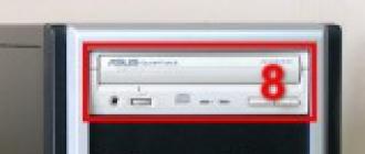
On the front panel of the system unit, you can see the “faces” of some internal devices:
- Optical drive (8) - for reading information from CDs or DVDs;
- Floppy drive - to read information from floppy disks (it is already much rarer, since it is morally obsolete);
- Internal card reader - A device for reading information from flash memory cards, which are used in cameras, video cameras, mobile phones.
We have seen enough of the front panel, we will look at the back one: “Izubshka-hut, turn around ...”
Here’s what the back panel of the system unit looks like (look at the photo, by the way, almost all the photos on the site’s website can be enlarged by clicking on them with the left mouse button):

There are already much more connectors. Most of the connectors of the system unit is at the back so as not to spoil the appearance of the workplace, and so that the wires do not get tangled under your feet (hands).
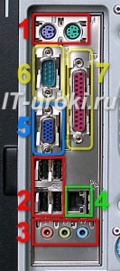
All rear panel connectors can be divided into three groups:
- Power connector (number 1 in the photo) - to connect the computer to the electrical network. A cord is inserted into this connector, on the other end of which is a regular plug (“Euro” format). Near the power connector there is a button that disconnects the system unit from the electrical network. If the computer does not turn on - check this button, suddenly someone pressed it without your knowledge.
- Standard connectors (2) - a group of connectors to which you can connect a keyboard, mouse, audio system, and other external devices.
- Additional connectors (3) - conclusions from additional internal devices (we will talk about them in one of the following). The photo shows that there is only one device installed (video adapter) to which the monitor can be connected.
This division is conditional. In fact, the connectors in group 3 may overlap with the connectors in group 2 (this depends on the internal configuration of the computer), in this case it is preferable to use connectors from the third group.
Standard and optional rear panel connectors
Let's look at the standard larger connectors:
I distributed the numbering according to the importance of the connectors for us:
- Keyboard and mouse connectors (1 in the photo) - the keyboard is connected to the purple connector, and the mouse is connected to the green connector. Sometimes these connectors are missing, in which case both the keyboard and the mouse are connected to the USB connectors (the next item).
- ConnectorsUSB (2) - most of various external devices are connected to them (printer, scanner, external card reader, flash drive, and much more). USB connectors can be from four to twelve.
- Audio Connectors (3) - the speaker system or headphones are connected to green connector, microphone - to pink connector, and to blue connect various players (and other sound devices to record sound on a computer).
- Computer network connector (4) - a computer network cable is connected to this connector, through which you can connect to the Internet or exchange data with other computers.
- Monitor connector (5) - this connector is not always in this group. If there is no such connector, then look for it below among the additional connectors. By the way, the monitor connector can be of two types (blue or white, less often yellow).
- Connectors marked with numbers 6 and 7 (serial and parallel ports) are found on relatively old computers. Previously, they were used to connect printers, scanners, mice, and other devices that are now plugged into USB connectors (item 2 in this list).
This concludes familiarity with the external device of the computer. In more detail about the external device of the PC - in the following lessons, but already when you go to a higher level of knowledge (user and experienced user).
How properly connect and disconnect devices You can learn in one of the following IT lessons.
The following lesson is small but very important:
SCSI (Small Computer System Interface), pronounced "tales" - a system-level interface standardized by ANSI, as opposed to interface ports (COM, LPT, IR, MIDI), is a bus: the signal pins of multiple device subscribers are connected to each other " one to one. " The main purpose of the SCSI bus during the development of the first specification in 1985 was “to ensure the hardware independence of devices of a certain class connected to a computer”. In contrast to the hard expansion buses, the SCSI bus is implemented as a separate cable stub, which allows connection of up to 8 devices (SCSI-1 specification) of internal and external performance. One of them - host adapter (Host Adapter) connects the SCSI bus to the computer system bus, seven others are free for peripherals.Figure 1. ASUSTeK SCSI adapter The bus can be connected to: · disk internal and external drives (CD-ROM, hard drives, removable hard drives, magneto-optical disks, etc.); · Streamers; · Scanners; · Photo and video cameras; · Other equipment used not only for the IBM PC. Each device connected to the bus has its own identifier SCSI ID, which is transmitted by the position code on the 8-bit data bus (hence the restriction on the number of devices on the bus). The ID can have up to 8 sub-devices with its own LUN (Logical Unit Number). Any device can initiate an exchange with another. target device (Target). The exchange mode over the SCSI bus can be: · asynchronous, or · synchronous with speed negotiation (Synchronous Negotiation), where data transfer is controlled at parity.
SCSI specifications
SCSI-1 specification strictly defines the physical and electrical parameters of the interface and a minimum of commands. The bus frequency is 5 MHz. The bus width is 8 bits. The ANSI standard was developed in December 1985. SCSI-2 specification defines 18 basic SCSI commands (Common Command Set, CCS), mandatory for all peripheral devices, and additional commands for CD-ROM and other peripherals. Devices support queues - they can receive chains of up to 256 commands and execute them in a pre-optimized manner autonomously. Devices on the same SCSI bus can exchange data without CPU involvement. The ANSI standard was developed in March 1990. Additional SCSI-2 specification extensions: · Fast - doubling the speed of synchronous transmission (10 MHz bus frequency). · Ultra - ultra-fast interface (20 MHz bus frequency). · Wide - increase in digit capacity to 16 bits, is more rare 32 bits. The maximum throughput depends on the frequency and bit width of the bus, and for the combinations of these extensions is given in Table. one.Table 1. Data transfer rate, length and types of SCSI-1, SCSI-2 cables SCSI-3 specification - further development of the standard, aimed at increasing the number of connected devices, the specification of additional commands, support for Plug and Play. As an alternative to parallel interface SPI (SCSI-3 Parallel Interface) the possibility of applying a serial, including fiber-optic interface with a data transfer rate of 100 MB /. SCSI-3 exists in the form of a wide range of documents defining individual sides of the interface, and largely interlocks with the serial bus. Firewire.
Terminators, connectors
By type of signals distinguish linear (Single Ended) and differential (Differential) SCSI versions, their cables and connectors are identical, but electrical compatibility there are no devices between them. Differential the version for each signal uses a twisted pair of conductors and special transceivers, and the total length of the cable becomes permissible, while maintaining a high frequency of exchange. The differential interface is used in powerful server disk systems, but in ordinary PCs it is not common. AT linear the version of the signal must go along its own conductor, twisted (or at least separate from the other in a flat cable) with a zero (return) wire. Universal symbolic designations of versions are shown in Figure 1. SCSI devices are wired to chain (Daisy Chain), on the extreme devices are connected terminators. Often one of the extreme devices is the host adapter. For each channel, it can have both an internal connector and an external connector:| Internal connectors | |
| Low-Density 50-pin |
connection of internal narrow devices - HDD, CD-ROM, CD-R, MO, ZIP (as IDE, only for 50 contacts) |
| High-Density 68-pin |
connection of internal wide devices, mainly HDD |
| External connectors | |
| DB-25 |
25 connecting external slow devices, mainly scanners, IOmega Zip Plus. most common on Mac. (like a modem) |
Low-Density 50-pin  |
or Centronics 50-pin. external connection of scanners, streamers. usually scsi-1. |
| High-Density 50-pin |
or Micro DB50, Mini DB50. Standard external narrow connector |
| High-Density 68-pin |
or Micro DB68, Mini DB68. Standard external wide connector |
| High-Density 68-pin |
or Micro Centronics. According to some sources it is used for external connection of SCSI devices. |
When simultaneously using the external and internal connectors of the host adapter, its terminators are disconnected. The correctness of the use of terminators is essential - the absence of one of the terminators or, conversely, an extra terminator can lead to instability or loss of the interface. By execution, terminators can be either internal (placed on the PCB of the device) and external (mounted on cable or device connectors). The following types of terminators are distinguished by their electrical properties: Passive (SCSI-1) with an impedance of 132 Ohms — ordinary resistors. These terminators are not suitable for high-speed SCSI-2 modes. · Active with an impedance of 110 Ohms - special terminators to ensure operation at a frequency of 10 MHz in SCSI-2. · FPT (Forced Perfect Terminator) - an improved version of active terminators with emission limiters. Active terminators require power, for which there are special TERMPWR interface lines.
SCSI devices
It is not possible to list all SCSI devices, we will list only a few of their types: hard disk, CD-ROM, CD-R, CD-RW, Tape (streamer), MO (magneto-optical drive), ZIP, Jaz, SyQuest, scanner. Among the more exotic, we note Solid State disks (SSD) - a very fast mass storage device on chips and IDE RAID - a box with n IDE disks, which pretends to be one large SCSI disk. In general, we can assume that all devices on the SCSI bus are the same and use one set of commands to work with them. Of course, as the physical SCSI layer evolved, the software interface also changed. One of the most common today is ASPI. On top of this interface, you can use the scanner drivers, CD-ROMs, MO. For example, the correct CD-ROM driver can work with any device on any controller if the controller has an ASPI driver. By the way, Windows95 emulates ASPI even for IDE / ATAPI devices. This can be viewed, for example, in programs like EZ-SCSI and Corel SCSI. Each device on the SCSI bus has its own number. This number is called a SCSI ID. For some purposes, for example, in the CD-ROM device libraries, another LUN is used — the logical device number. If in library 8 CD-ROMs, then it has a SCSI ID, for example, 6, and logically CD-ROMs differ in LUN. For the controller, all this looks like SCSI ID pairs — LUN, in our example, 6-0, 6-1, ..., 6-7. LUN support, if necessary, must be enabled in the SCSI BIOS. The SCSI ID number is usually set with jumpers (although there are new standards in SCSI that are similar to Plug & Play and do not require jumpers). They can also set the parameters: parity check, turn on the terminator, power the terminator, turn on the disk at the command of the controller. All SCSI devices require special drivers. The basic disk device driver is usually included in the host adapter BIOS. Extensions, such as ASPI (Advanced SCSI Programming Interface), are downloaded separately.Scanners
Usually, the kit of scanners includes its own card. Sometimes it is completely "own", as, for example, in the Mustek Paragon 600N, and sometimes it is simply the most simplified version of standard SCSI. In principle, using a scanner with it should not cause problems, but sometimes connecting the scanner to another controller (if the scanner has such an opportunity) can be beneficial. Scanning A4 from 32 bits in color to 600dpi is a picture of about 90Mb and transferring this amount of information over 8 bits to the ISA bus not only takes a lot of time, it also slows down the PC a lot, since The drivers for this standard card are usually 16 bit (for example, Mustek Paragon 800IISP). As an additional, a cheap FastSCSI PCI controller is usually used. Less or more productive will not give anything new. In this version there is also a remark - you need to make sure that the scanner (or more importantly, its drivers) can work with your new controller in your configuration. For example, Mustek Paragon 800IISP drivers are designed for your card or any ASPI compatible.
RS-232 serial port
RS-232 (English Recommended Standard) - the standard for serial asynchronous transfer of binary data between two devices at a distance of 15 meters. The RS-232 port is not often found in business laptops lately, but it can be useful in industrial laptops. It is used to implement real-time data acquisition systems, connect scientific equipment, and control other devices. To connect RS-232 equipment, laptops are equipped with a 9-pin DB-9 (D-sub) connector.
Posted January 16, 2017Hello my dear readers, today I would like to touch on such an important topic as the basic connectors of the system unit. Let's see why they are needed and what can be connected to them?
I personally believe that each user, more or less frequently using a computer, simply must know the main connectors of the system unit in order to be able to later connect new equipment to the computer or be able to assemble a computer in a new place.
Many of you probably already faced with the assembly of a computer, but surely few people did everything right the first time. In this article, I would like to review the main connectors of the system unit and figure out what they serve for, so that later you will not have problems when building a computer or installing new hardware.
So, let's begin. Below I will give a typical system unit with explanations. Later we will understand why each port serves.
In the picture we see a typical system unit, a bit outdated, but I think it will work for ours.
Connectors for network cables
At the very top of the system unit, we see the power supply connector (or abbreviated BP) for connecting the computer to the network. Under it, they usually mold a sticker with the allowed input voltage. For example, 220 V. Under the connector is a tubler, which can be switched to the position "0" and "I". Correspondingly 0 - current supply is not allowed, I - current supply is allowed.
Now a little about what a power supply. The power supply is a voltage converter, which is present in each system unit. It receives the current from your home network and converts it into the necessary for the computer, as he distributes it through his wiring between the internal components of your system unit. Such as motherboard, hard drives, video card and external coolers. It looks something like this:

And more productive and modern like this:
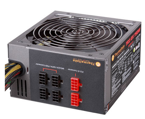
Like the main system unit, it also has its own specialized connectors for connecting internal components to it of the system unit itself. On hard drives alone, on coolers others, and on the motherboard third. But we will not go into details of the power supply unit today, because the article is not about that. And if the power supply is already installed in the system unit, then everything has already been connected to you.
However, the power supply itself is simply not inserted into the outlet. Need a special network cable. It looks like this:

One end of the cable is plugged into a regular outlet, and the other is connected to the connector in the power supply. Therefore, in order to power our system unit with all its internal components, we need to connect the power supply unit to the outlet with a cable and switch the toggle switch on the power supply unit to the current supply position - "I".
Motherboard connectors
So, with the power supply sorted out. Now go to the connectors of the motherboard. This is the largest and most basic board inside your system unit, so the largest number of different connectors comes from it. By the way, it looks like this:
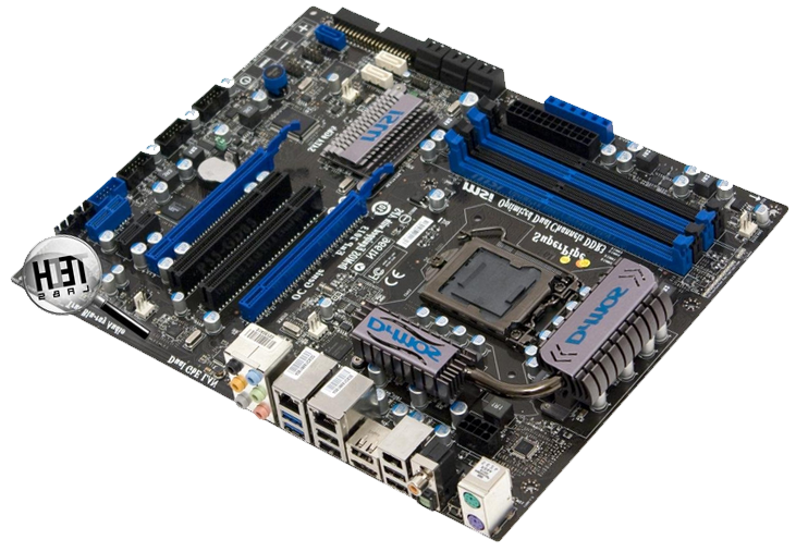
And from the connectors on it most often there are ps / 2 ports, usb jacks, graphic connectors, a connector for a network cable and outputs for audio devices (microphone, speakers, amplifier, etc.)
Keyboard and mouse connectors
In the very top row of motherboard connectors are two PS / 2 ports.

They are always nearby and are used to connect the keyboard and mouse. Green to connect the mouse, purple to connect the keyboard. The connectors are exactly the same, differ only in color. Therefore, they are often confused with each other. Even the color difference does not help. After all, for most users, the computer is at the bottom, under the table, turned with its back panel to the wall, where there is utter darkness. Only one way out - a flashlight. But there is a little trick. The connector for the mouse is often on the right side, and for the keyboard on the left. This connector is outdated long ago, lately it can be found less and less. On the latest models where it is still used, these two ports are combined into one and can connect both a mouse and a keyboard.
Obsolete connectors
After the PS / 2 ram under the mouse and the keyboard on modern motherboards, usb 2.0 and usb 3.0 ports usually go right away, but on earlier motherboards there are still monsters like these that are incomprehensible to the modern user:

This is a parallel LPT connector. It is obsolete and has been replaced by the universal USB port, which I will describe below. The LTP connector was once developed by IBM and was used to connect peripheral devices (printers, modems, etc.) in MS-DOS.
You may also encounter such a port:

This is a serial COM port. Also obsolete. The word sequential means that data is transmitted through it sequentially, one bit at a time. Previously, it was used to connect terminals, network devices and a mouse. Nowadays, it is sometimes used to connect satellite receivers, uninterruptible power supplies and security systems.
Below are already familiar to most of you USB ports. These are the ones into which we insert our flash drives, printers, usb charging for phones and many other things. Currently, there are several types of these ports. The most popular ones are usb 2.0 and usb 3.0
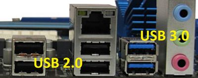
They differ in color and data transfer rate. USB 2.0 port is black and its data transfer speed is about 30 MB / s, while USB 3.0 has about 300 MB / s. USB 3.0 ports are always blue or bright blue.
Of course, sharing my usb ports on 3.0 and 2.0 is a barbaric method, because there are still many different submodifications like usb 2.0 full-speed, usb 2.0 high-speed and usb 3.1, but for our purposes I think division by 2.0 and 3.0 will be more than enough. If you suddenly find it interesting to learn about transitional options, you can open Wikipedia. There everything is painted in detail.
I probably will not stop in more detail on usb ports, because today every schoolchild knows what they are used for. Let me just say that these ports can not only transmit data, but can also transmit a small voltage current. From here, just all these usb charging for mobile devices. And they support branching. This means that with sufficient voltage and the presence of a usb hub (the language of the extension cable), up to 127 devices can be connected to one usb port.
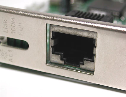
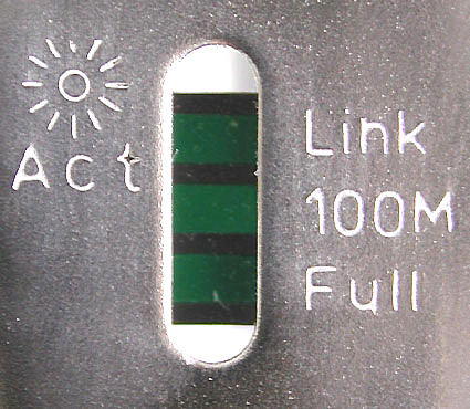
ethernet socket
Under usb ports or near them is the Ethernet socket.
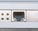
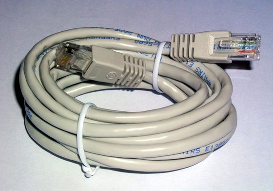
It is used to connect a computer to any internal network or global Ethernet network. It all depends on the circumstances and desires of the owner. Computers are connected to the global network or are connected to local networks, of course, not just like that, but by means of a network cable. At both ends of which there are RJ 45 connectors to connect to the connectors of network devices. Here is a view of a standard network cable:
Audio jacks
On this board are jack 3.5 connectors. Located in the bottom row of connectors on the motherboard and are used to connect various acoustic input / output devices to the computer.
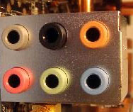
Pink connector is used to connect a microphone, or rather for audio input devices. Green is a linear output and is required for audio output devices (headphones, speakers). The blue connector serves to receive a sound signal from external subsystems (radio, portable or other player, or TV)
If your motherboard has 6 connectors, then your sound card is designed to work in 4-channel mode. The orange connector, in this case, is designed to connect a subwoofer (low-frequency phone). Gray for extra side. Black for rear (rear).
Recently, the color designations of the connectors are very conditional and, if necessary, with the help of drivers, they are adjusted as needed for other functions. For example, to connect additional headphones to the microphone jack - it’s enough when connecting to the driver that this device is an output device (speakers or headphones).
Video connectors
Well, at the very bottom, apart from the motherboard connectors, we see video connectors coming from an external video card or between the motherboard connectors if you have it built-in. A short explanation of the differences. An external (discrete) video card is one that is separated from the motherboard. Ie it is not soldered there, but is connected via the PCI-Express connector on the motherboard. As a rule, an external video card is much more powerful than a built-in video card. The integrated video card is soldered to the motherboard and, in fact, is its inseparable part. The last few years, the integrated video cards have been part of the processor and, during operation, take power from it and separate part of the RAM for themselves.
Video connectors are needed to connect monitors or televisions to a computer. Sometimes you can also find a TV-out for connecting a television antenna, but this is more often only in cases when one more additional fee is purchased for receiving a TV signal in the system unit. Usually you can find only video connectors for connecting monitors.
The most common, at the moment, is the HDMI (High Definition Multimedia Interface) interface.
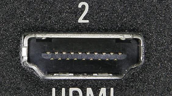
This interface is present in modern video cards, monitors and TVs. The main feature of HDMI is the ability to transmit high-definition digital video signal (HDTV with resolution up to 1920 × 1080 pixels), as well as multi-channel digital audio and control signals over a single cable.
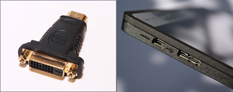
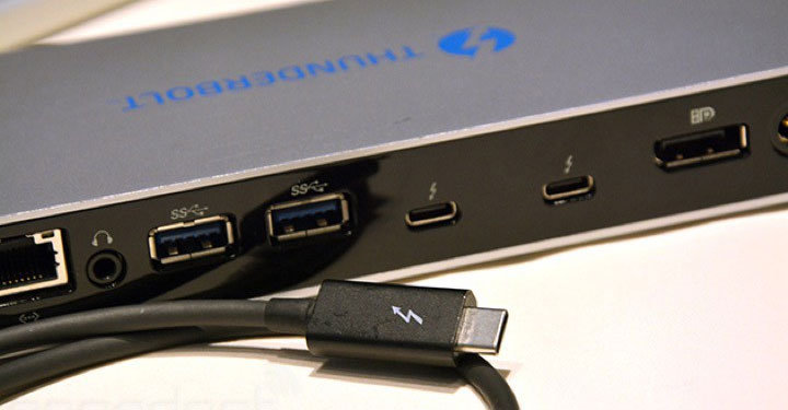
A little less common, but also quite common, is DisplayPort.

The technical characteristics of it is not much different from the HDMI connector, but unlike the previous one, it does not require any license fees from the manufacturer. Due to this, it is quickly gaining popularity among manufacturers. At present, this port is actively being supplanted by the Thunderbolt connector, which looks exactly the same, supports backward compatibility and at the same time has significantly more features. The data transfer rate of the Thunderbolt connector reaches 40 Gbps. It has less power consumption and allows you to connect up to two monitors with a resolution of 4K, or one with a resolution of 5K.
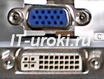
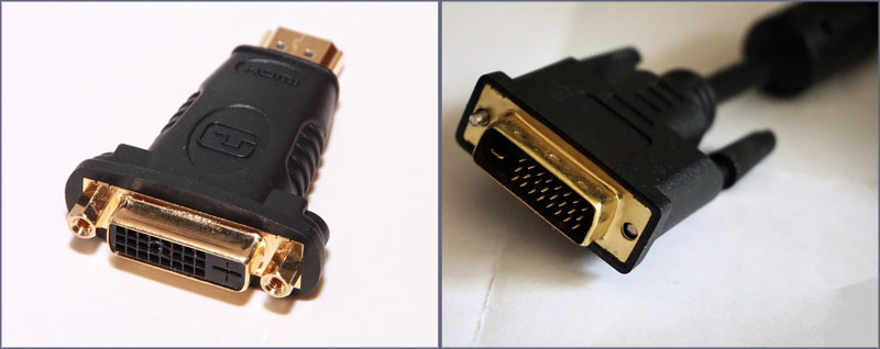
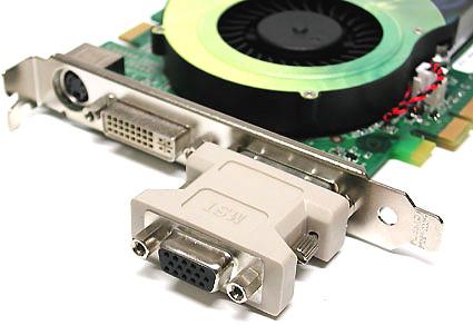
The first of the obsolete monitor connectors is called DVI.
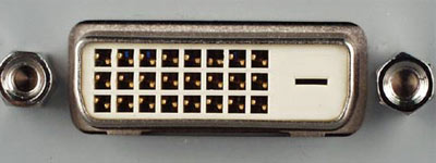
This connector is designed to transfer images to high-precision digital display devices. It was developed by Digital Display Working Group
Analog connector for legacy monitors is called VGA
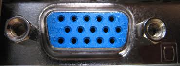
The connector is considered obsolete. And it is used to connect analog monitors. In such monitors, the signal is transmitted line by line. And when the voltage changes, the screen brightness changes. This connector was developed back in 1987 by IBM
Modern computers or mobile gadgets are equipped with a wide range of ports, from traditional USB 2.0 to the new-fashioned Thunderbolt 3. Even if you are all familiar with them, time passes and technical progress generates a new standard of power or reception and transmission, which require new adapters. Find out which wires and adapters are needed in order to connect a computer to a monitor, TV, network, gadget and other peripheral device.
When you purchase a new laptop or desktop computer, it is always interesting to know: which connectors and ports are on board. In addition, knowledge will always come in handy that will help you to know if your device will benefit from the transfer speed if you attach it to the modern usb type-c port, and not to the outdated usb 2.0. That is why I tried to collect a complete list of ports, as well as the type and cost of adapters that you can meet with when mating a computer or laptop and your gadgets.
Description: The most common audio jack in the world. On most computers, tablets and phones is designed as a 3.5 mm connector and connects most wired headphones, speakers with a computer or gadget. Moreover, computers, as a rule, have two or more audio jacks for microphone and headphones, speakers for 3.1, 5.1 or even 7.1 audio formats. And mobile gadgets have only one headset port.
Adapter need: If your device does not have a 3.5mm jack, you may want to consider purchasing a wired USB headset or a Bluetooth wireless audio device or adapter USB-to-3.5 mm. Fortunately, the cost of each option exceeds $ 10.
3.5 mini jack adapter options
Ethernet Network Port (RJ-45)
Also known as: Gigabit Ethernet, 10/1000 Ethernet, LAN port.
Description: Focuses primarily on the business segment of devices - servers and switches, laptops and computers. This port allows you to directly connect to wired networks. While Wi-Fi continues to increase the speed of the wireless connection, Ethernet has long been able to work at a speed of 1 Gbit / s over the wire. Having such a speed is really very convenient, because the speed of data transmission nowadays plays a decisive role if you have the option of choosing an Internet connection interface. Ethernet in business unites millions of office computers in a local area network, transmits tens of gigabits of traffic in the largest data centers.
At home, if you have more than one computer, a TV with a LAN port, you should think about the organization of the local network. Such a data transfer rate and at the same time network stability and lack of interference will not be offered to you by any network standard available today.
Adapter need: If you do not have a built-in Ethernet port, you can consider purchasing an adapter USB-to-Ethernet. The cost is on average from $ 15 to $ 30, depending on the type of USB: Type-C or Type-A. For some mobile devices, Ethernet can be obtained by connecting to the docking station.
 Ethernet RJ-45 cable
HDMI connector
Also known as: interface for high definition multimedia.
Description: This popular connector is most common for connecting devices to a TV, and also appears on many monitors and projectors. Depending on your laptop or desktop PC with a graphics card, the HDMI port (High-Definition Multimedia interface) may be able to output resolutions up to 4K. However, you can not display the image for two displays from one port. Also, HDMI transmits the audio signal along with the video. So if your monitor or television has speakers, you also get sound.
If your computer has HDMI output, and your monitor has DVI, you can convert the signal from one to another with an adapter that costs less than $ 5.
Most laptops that have HDMI use a full-sized port (Type A), but there are also ultra-thin devices that use HDMI mini-connectors: mini-HDMI (Type C) and micro-HDMI (Type D), which are physically executed in smaller forms -factor.
Adapter need: If you need to connect to the DVI port, we use HDMI-DVI An adapter that costs $ 5. For about $ 25 you can find an adapter USB (Type-C) -HDMI.
If you want to convert the signal from the HDMI port on a computer to a device with DisplayPort, the monitor, for example, will have to purchase a rather expensive active converter, which requires its own connection to a power source and costs more than $ 30. Cables DisplayPort-to-HDMI no power will not work.
 DVI-HDMI adapter, mini-HDMI port
DisplayPort / Mini DisplayPort
Also known as: dual-use port.
Description: DisplayPort today is the most advanced standard for connecting monitors to computers, with the ability to output images to one monitor with a resolution of 4K and 60 Hz, or up to three monitors in Full HD format (using a hub or docking station). Most laptops that have DisplayPort use a Mini DisplayPort or DisplayPort Type-C mini connector via the USB port.
And yet most monitors and televisions do not have a DisplayPort connector, but you can display an image on an HDMI-compatible display through an adapter that costs less than $ 10. Like HDMI, DisplayPort can output audio in the same cable as video.
Adapter need: If you want to display an image on more than one monitor from one mini DisplayPort port on a laptop, then you need to be multi-threaded displayport hubwhich costs from $ 70 to $ 100 and needs electricity. One cable USB (Type-C) -to-DisplayPort or mini-displayport-to-displayportcable cost just over $ 10.
 mini-DisplayPort, DisplayPort
DVI port
Also known as: DVI-D, DVI-I, Dual-Link DVI.
Description: Due to the physical size of DVI, not every laptop is equipped with this interface. But almost every monitor with Full HD resolution has a DVI port. Often DVI will be the best option for connecting a computer and a monitor, as many budget displays have only DVI and VGA connectors. Fortunately, if the need arises, you can purchase an adapter to switch from HDMI or DisplayPort to DVI.
DVI can display images up to the resolution of 1920 x 1200 at 60 Hz. For 2K or 4K monitors at 30 Hz, a second connection is required - the so-called Dual-Link DVI. By virtue of its name, it can provide image output with a resolution of 1920 x 1200 at 120 Hz.
Most basic USB docking stations have at least one DVI output.
Adapter need: You can find the cable HDMI-DVI for less than $ 10 and DisplayPort DVI cable priced below $ 15. The cheapest cable is DVI-VGA about $ 5. USB docking stations with dual monitor DVI output start at $ 90.
 HDMI-DVI adapter, DVI cable
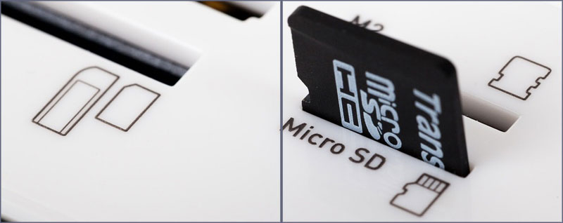
Microsd adapter
Also known as: slot for memory cards MicroSD, MicroSDHC reader, microSDXC.
Description: This slot reads microSD memory cards that the vast majority of modern smartphones, tablets, music players and other mobile gadgets use. If your laptop or tablet has a very limited amount of internal disk memory, then microSD adapter Will save you. It will allow to expand the internal memory due to the volume microSD memory card with 64 GB or 128 GB.
Adapter need: If your device does not have a built-in microSD card slot, then I advise you to purchase an external microSD adapterthat will cost you about $ 10.
 Microsd adapter
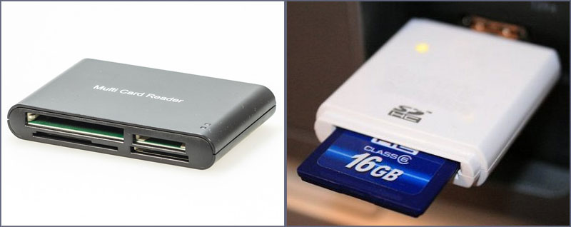
Sd adapter
Also known as: 3-in-1 card reader, 4-in-1 card reader, 5-in-1 card reader, SDHC card reader.
Description: This slot can be used to read memory cards from a digital camera format SD.
Adapter need: If you often transfer photos from a digital SLR camera to a laptop or desktop computer, I strongly advise you to purchase an SD card reader. It connects via USB and costs just under $ 10.
 5-in-1 card reader, SDHC adapter
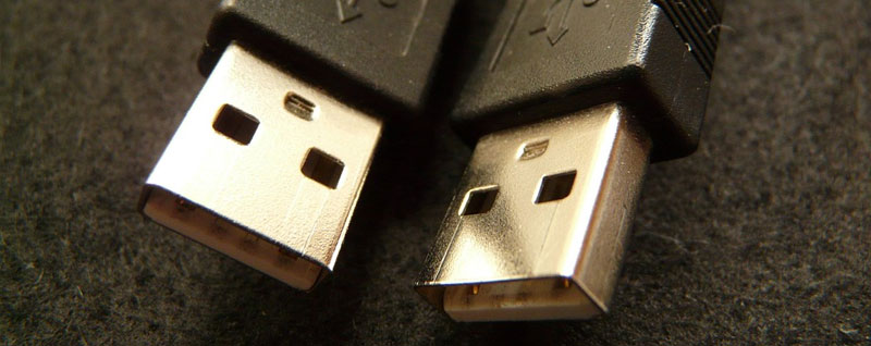
USB / USB Type-A
Also known as: USB Type-A, normal USB,
DescriptionA: Today, USB (universal serial bus) is the most common connector for laptops and computers. A regular USB port is known as USB Type-A and has a simple, rectangular shape. Depending on the hardware version, it can be either USB-2.0 or USB-3.0, which differ significantly in speed.
Speed indicators
USB 1.1
- low bandwidth mode (Low-Speed) - 1.5 Mbit / s maximum;
- high-bandwidth mode (Full-Speed) - 12 Mbps maximum.
- Preserves physical and functional compatibility with USB 1.1;
- low-speed mode, 10-1500 Kbit / s (keyboards, mice, joysticks, gamepads);
- full-speed mode, 0.5-12 Mbit / s (audio, video devices);
- high-speed mode, 25-480 Mbit / s (video devices, storage devices).
- Preserves physical and interoperability with USB 2.0;
- maximum data transfer rate up to 5 Gbps.
You can connect an almost infinite variety of peripherals to a USB port: from keyboards and mice to printers and Ethernet adapters. Regular USB does not have its own standard for transferring video, but you can connect to the monitor using a universal docking station or adapter with DisplayLink technology.
 Plain USB 2.0 Type A cable
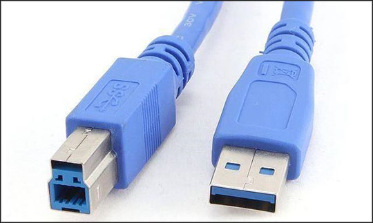
USB Type-B
Description: You will not find this square connector on the motherboard of the computer, it is not placed on the side of the laptop. It is used in peripheral devices as an input port: docking stations, printers, scanners and others. All of these devices will need a cable. USB Type-A - Type-Bwhich can be easily found in any computer store.
 USB Type-B
USB Type-C
Also known as: USB-C.
DescriptionA: This thin USB port is the newest USB standard. The port is already available on a number of devices, and is likely to replace USB Type-A, USB Type-B and MicroUSB on all new systems in the near future. It is much thinner than its predecessors. Type-C can fit on very thin laptops, such as the MacBook 12 ". USB Type-C connector is symmetrical, so you never have to worry about the position of the plug when plugged into a port that allows you to insert a cable by either side. Apple with its Lightning connector clearly demonstrated this by incorporating USB Type-C into all of its devices.
USB Type-C ports can support several different standards, but not all of them offer the same functionality. Type-C can transfer files to either USB 3.1 Gen 1 (5 Gbps) or USB 3.1 Gen 2 (10 Gbps). It can be used as a charging port (USB-PD), so you can charge your laptop with it. It can also transmit DisplayPort signals, and even work as a Thunderbolt port.
Adapter need: If you have a rectangular-shaped USB Type-A port, but you need to connect a device with a USB Type-C cable, use USB-C 3.0 (Type C) - USB-A 3.0.
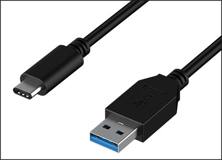 USB Type-C Cable - USB Type-A
USB 2.0 interface
Also known as: high-speed USB, USB 2.
Description: The ability to transfer data at speeds of up to 480 Mbps, USB 2.0 is the most common USB and works effectively with most peripheral devices. The USB 2.0 port can be made in various form factors: Type A - Type A (rectangular), Type B - Type-B (square), mini - mini USB or micro - micro USB. On laptops and desktops, a USB 2.0 port will always be type A, while on tablets and phones, it will most likely be micro USB.
 USB 2.0 ports
USB 3.0 interface
Also known as: SuperSpeed USB, USB 3.
Description: Great for external hard drives, SSDs, high resolution monitors, docking stations, USB 3.0 has a maximum transfer rate of 5 Gbps. It is more than 10 times faster than its predecessor USB 2.0. USB 3 ports are automatically backward compatible with USB 2.0 cables and devices. USB 3 ports on a computer use a rectangular connector type and, as a rule, are no different from their younger counterparts. Sometimes SuperSpeed USB 3.0 ports are dyed light blue or put a tiny “SS” logo next to them to indicate their higher data transfer speeds.
 USB 3.0 cable
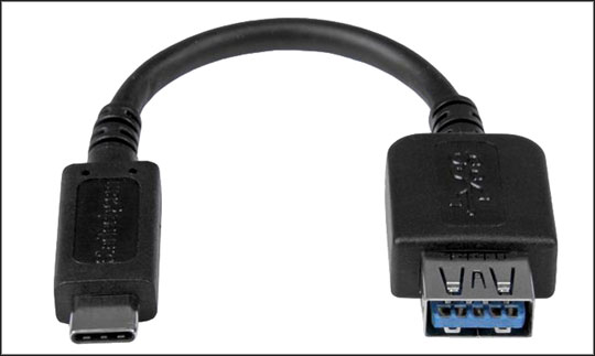
USB 3.1 Gen 1
Also known as: USB 3.1, SuperSpeed USB.
Description: USB 3.1 Gen 1 is a communication protocol that works at the same 5 Gb / s speed as USB 3.0, but it only works with USB Type-C. This gives backward compatibility with USB 3.0 and USB 2.0 devices, provided that the cable has a Type-C connector on at least one side. USB 3.1 devices can support USB devices that allow them to receive or transfer power at speeds up to 100 watts, which is enough to charge most laptops.
 USB 3.1 Gen 1
USB 3.1 Gen 2
Also known as: USB 3.1, SuperSpeed + USB, SuperSpeed USB 10Gbps.
Description: The USB 3.1 Gen 2 form factor is the same as the USB 3.1 generation 1, but with doubled bandwidth, which allows it to transfer data at speeds up to 10 Gbit / s. To ensure backward compatibility with USB 3.1 Gen 2 USB adapters, a type C connector is required, but to use it at full speed, you need to make sure that the cable is designed for 10 Gbps. This is usually marked with the logo "ss" or blue.
 USB 3.1 Gen 2
Micro usb
Also known as: Micro-B, MicroUSB.
Description: This small port has gained a reputation as a port for charging smartphones and low-power tablets. This connector is not used on laptops and PCs. Regular micro USB supports USB 2.0 speed (480 Mbps) and allows you to connect multiple devices, mostly external hard drives. Micro USB 3.0 ports have some additional pins and offer a higher transfer rate, but their form factor is exactly the same as micro USB 3.0.
Adapter need: In order to connect a phone or tablet to a laptop USB Type-A - micro USB cable, which costs about $ 5. You can also use an adapter. Type-C - Micro USBfor $ 10.
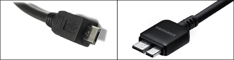 Micro USB 2.0, Micro USB 3.0
Mini usb
Also known as: Mini-B, mini USB.
Description: The interface is already less popular than micro USB, since it is older. Used on some external hard drives, game consoles and other accessories. They, like micro USB, are not used on laptops and computers. They can be found on mobile phones, or some players. But even with the advent of micro USB, the use of this port is a rarity these days.
Adapter need: cable Type-A - mini USB costs about $ 5, A cable Type-C - Mini USB available for less than $ 10, and an adapter micro usb - usb will cost about $ 5.
 Type-A cable - mini USB, micro USB - USB adapter
Thunderbolt 3
Also known as: Thunderbolt.
DescriptionA: The fastest connection on the market today. Thunderbolt 3 can transfer data at speeds up to 40 Gbps, which is four times faster than the fastest USB (USB 3.1 Gen 2). This high-speed standard can also display an image on two 4K monitors at once, because one Thunderbolt 3 port transmits dual DisplayPort signals. Thunderbolt 3 can be used to connect an external video card, which allows you to play games at maximum resolution using even an ultra-thin laptop.
All Thunderbolt 3 ports use the USB Type-C standard, which allows them to connect to a variety of peripherals using USB.
Thunderbolt 3, which appeared on laptops at the end of 2015, was Thunderbolt 2 standard, but very few vendors wanted to use it in their systems. Connection backward compatibility is stored in Thunderbolt 3, and if you have a device with the first version of Thunderbolt, you will not need to buy anything.
 Thunderbolt 3
VGA connector
Description: Now we can say: VGA is the great-grandfather of video outputs. VGA (video graphics array) appeared back in 1987, but so far this connector is a common phenomenon on many monitors and projectors even today. However, since the 15-pin connector is rather large, you will not find more current-generation laptops or desktop computers that have a VGA output. This analog connection leads to signal distortion on longer cables, and displays an image with a maximum resolution of up to 1920 x 1200 pixels.
Adapter need: Convert VGA to any other video signal is impossible due to the fact that the VGA analog signal, and the rest are already digital (DVI, DisplayPort, HDMI). But you can connect a different connector to a VGA monitor using an inexpensive wire or adapter, such as cables or adapters: DVI-VGA, HDMI-VGA or DisplayPort-VGA. Their cost rarely exceeds more than $ 10.
"Daddy" should approach "mom"
Each computer, whether desktop or laptop, uses a huge number of connectors, both inside and outside. Can you name each one and explain the purpose? Books often have too bad descriptions, or they are not sufficiently illustrated. As a result, readers are often confused and lost.
In our full guide, we will try to solve this problem by sorting out all existing interfaces. We have equipped the article with a large number of illustrations, which will visually tell about the slots, ports and interfaces of your PC, as well as about the whole range of devices that can be connected to them. Especially our manual will be useful for beginners who often do not know the purpose of an interface. And it is required to connect the periphery now.
But there is one consolation: almost every connector is very difficult (or even impossible) to connect incorrectly. With rare exceptions, you can not connect the device "not there." If there is such an opportunity, we will definitely warn you. Fortunately, the damage associated with improper connection, today are not as common as before.
We have broken the manual into the following parts.
- External interfaces for connecting peripherals.
- Internal interfaces located in the PC case.
External interfaces for connecting peripherals
USB
Connectors Universal Serial Bus (USB) are used to connect external peripherals such as a mouse, keyboard, portable hard disk, digital camera, VoIP phone (Skype) or a printer to a computer. Theoretically, up to 127 devices can be connected to a single USB host controller. The maximum transfer rate is 12 Mbps for the USB 1.1 standard and 480 Mbps for Hi-Speed USB 2.0. The USB 1.1 and Hi-Speed 2.0 connectors are the same. The differences lie in the transmission speed and the set of functions of the computer USB host controller, and the USB devices themselves. More details about the differences can be found in our article . USB provides power to devices, so they can operate from an interface without additional power (if the USB interface provides the necessary power, no more than 500 mA at 5 V).
There are three types of USB-connectors.
- Connector "type A": usually present in the PC.
- "Type B" connector: usually located on the USB device itself (if the cable is removable).
- Mini USB Connector: Usually used by digital video cameras, external hard drives, etc.

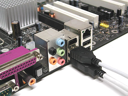
USB "type A" (left) and USB "type B" (right).
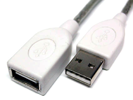
USB extension cable (must be no longer than 5 m).
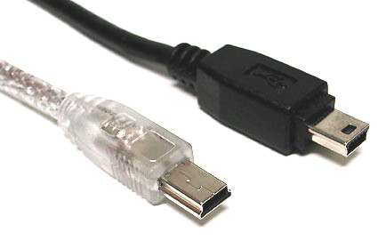
Mini USB connectors are commonly found on digital cameras and external hard drives.

The USB logo is always present on the connectors.

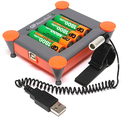
Double cable Each USB port provides 5 V / 500 mA. If you need more power (say, for a mobile hard drive), then this cable allows you to be powered from the second USB port (500 + 500 = 1000 mA).
Original: in this case, USB only provides power to the charger.

USB / PS2 adapter.
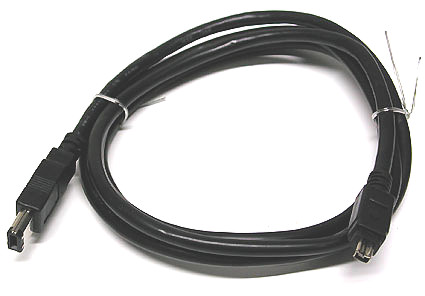
Firewire cable with 6-pin plug on one end and 4-pin plug on the other.
Under the official name IEEE-1394 hides a serial interface, commonly used for digital video cameras, external hard drives and various network devices. It is also called FireWire (from Apple) and i.Link (from Sony). Currently 400-Mbps IEEE-1394 standard is replaced by 800-Mbps IEEE-1394 b (also known as FireWire-800). Typically, FireWire devices are connected through a 6-pin plug that provides power. The 4-pin plug is not powered. FireWire-800 devices, on the other hand, use 9-pin cables and connectors.

This FireWire card provides two large 6-pin ports and one small 4-pin.
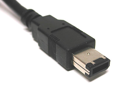
6 pin power connector.
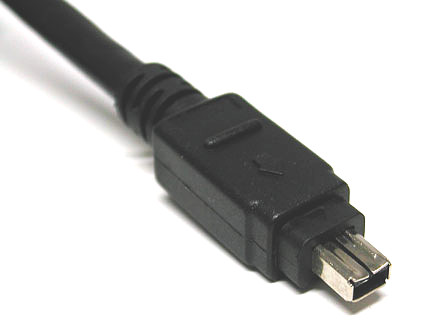
4-pin connector without power. This is usually used on digital video cameras and laptops.
Tulip (Cinch / RCA): composite video, audio, HDTV
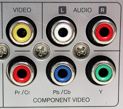
Color coding is welcome: yellow for video (FBAS), white and red “tulips” for analog sound, and three “tulips” (red, blue, green) for component HDTV output
Tulip connectors are used in conjunction with coaxial cables for many electronic signals. Tulip forks usually use color coding as shown in the following table.
| Colour | Using | Signal type |
| White or black | Sound, left channel | Analog |
| Red | Sound, right channel (also see HDTV) | Analog |
| Yellow | Video, composite | Analog |
| Green | Component HDTV (Brightness Y) | Analog |
| Blue | Component HDTV Cb / PB Chroma | Analog |
| Red | Component HDTV Cr / Pr Chroma | Analog |
| Orange / yellow | SPDIF sound | Digital |
A warning. You can confuse the SPDIF digital plug with an analog composite video connector, so always read the instructions before connecting the equipment. In addition, the color encoding of SPDIF is completely different. Finally, you can confuse the red "tulip" HDTV with the right audio channel. Remember that HDTV plugs are always in groups of three, the same can be said about nests.
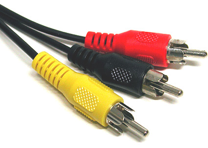
Tulip plugs have different color coding depending on the type of signal.
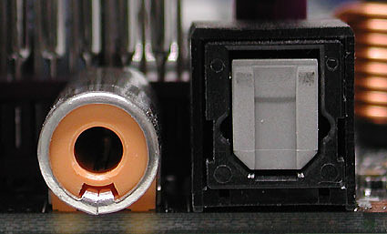
Two types of SPDIF (digital sound): Tulip on the left and TOSLINK (fiber) on the right.

The optical interface TOSKLINK is also used for SPDIF digital signals.
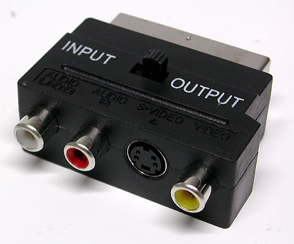
Scart-to-tulip adapter (composite video, 2x audio and S-Video)
Dictionary
- RCA = Radio Corporation of America
- SPDIF = Sony / Philips Digital Interfaces
PS / 2
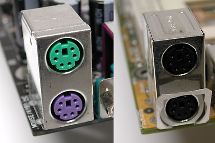
Two PS / 2 ports: one painted, the other not.
Named after the "old" IBM PS / 2, these connectors are now widely used as standard interfaces for keyboard and mouse, but they are gradually giving way to USB. Today the following color coding scheme is common.
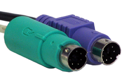
- Purple: keyboard.
- Green: mouse.
In addition, today, PS / 2 nests can be found quite often in a neutral color, both for the mouse and for the keyboard. It is quite possible to confuse the connectors for the keyboard and mouse on the motherboard, but it will not do any harm. If you do, you will quickly find an error: neither the keyboard nor the mouse will work. Many PCs won't even boot if the mouse and keyboard are not properly connected. To correct the error is very simple: swap the plugs, and it will work!
USB / PS / 2 adapter.
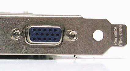
VGA port on graphics card.
The PC has been using the 15-pin Mini-D-Sub interface for a long time to connect a monitor (HD15). Using the right adapter, you can connect such a monitor to the DVI-I (DVI-integrated) output of a graphics card. The VGA interface transmits red, green, and blue signals, as well as horizontal (H-Sync) and vertical (V-Sync) sync information.
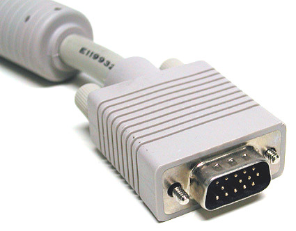
VGA interface on monitor cable.

New graphics cards are usually equipped with two DVI outputs. But with the help of the DVI-VGA adapter, you can easily change the interface (on the right in the illustration).
This adapter provides information for the VGA interface.
Dictionary
- VGA = Video Graphics Array
DVI is a monitor interface designed primarily for digital signals. That it was not required to translate digital signals of a graphic card into analog, and then perform the reverse conversion in the display.
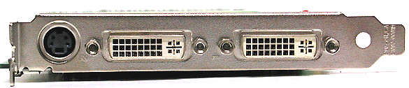
A graphics card with two DVI ports can work simultaneously with two (digital) monitors.
Since the transition from analog to digital graphics is slow, the developers of graphic equipment allow using both technologies in parallel. In addition, modern graphic cards can easily handle two monitors.
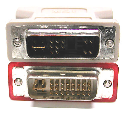
Widespread interface DVI-I allows you to simultaneously use both digital and analog connection.
Interface DVI-D is very rare. It allows only digital connection (without the ability to connect an analog monitor).
The kit with many graphics cards includes an adapter from DVI-I to VGA interface, which allows you to connect older monitors with a 15-pin D-Sub-VGA plug.
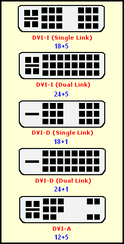
A complete list of DVI types (most commonly used interface with analog and digital DVI-I connections).
Dictionary
- DVI = Digital Visual Interface

RJ45 network cables can be found with different lengths and colors.
Networks are most commonly used connectors for twisted pair. Currently, 100-Mbps Ethernet is giving way to gigabit Ethernet (it works at speeds up to 1 Gb / s). But they all use RJ45 plugs. Ethernet cables can be divided into two types.
- A classic patch cable used to connect a computer to a hub or switch.
- Cross-crimped cable used to connect two computers together.
Network port on the PCI card.
Modern maps use LEDs to display activity.
In Europe and North America, ISDN devices and network equipment use the same RJ45. It should be noted that the RJ45 plugs allow "hot plugging", and if you make a mistake, nothing bad will happen.
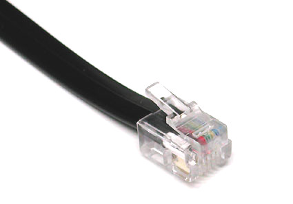
RJ11 cable.
The RJ45 and RJ11 interfaces are very similar to each other, but RJ11 has only four contacts, while RJ45 has eight. In computer systems, RJ11 is mainly used to connect to telephone line modems. In addition, there are many adapters for RJ11, as telephone sockets in each country can be their own standard.

RJ11 port on a laptop.

RJ11 modem interface.
![]()
RJ11 adapters allow you to connect different types of telephone jacks. On the illustration of the socket from Germany.
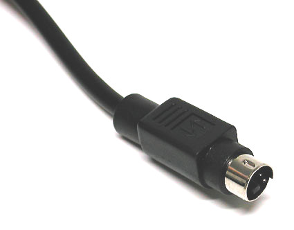
S-video interface.
Hosiden's 4-pin plug uses different lines for brightness (Y, brightness and data synchronization) and color (C, color). Separating the brightness and color signals allows for better picture quality than the composite video interface (FBAS). But in the world of analog connections in the first place in quality is still a component interface HDTV, followed by S-Video. Only digital signals like DVI (TDMS) or HDMI (TDMS) provide higher picture quality.

S-Video port on the graphics card.
Scart

SCART is a combined interface, widely distributed in Europe and Asia. This interface combines S-Video, RGB and analog stereo signals. Component modes YpbPr and YcrCb are not supported.
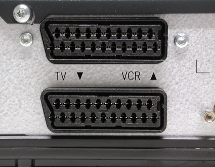
SCART ports for TV and VCR.
This adapter converts SCART to S-Video and analog audio ("tulips").
HDMI
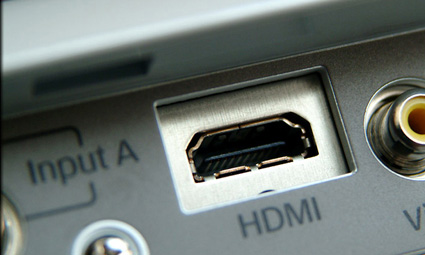
Before us is a digital multimedia interface for uncompressed HDTV signals with resolutions up to 1920x1080 (or 1080i), with Digital Rights Management (DRM) built-in copyright protection mechanism. Current technology uses 19-pin type A plugs.
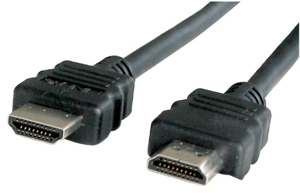
So far, we have not seen consumer equipment using 29-pin type B plugs supporting resolutions greater than 1080i. The HDMI interface uses the same TDMS signal technology as DVI-D. This explains the advent of HDMI-DVI adapters. In addition, HDMI can provide up to 8 channels of audio with a bit width of 24 bits and a frequency of 192 kHz. Please note that HDMI cables can not be longer than 15 meters.
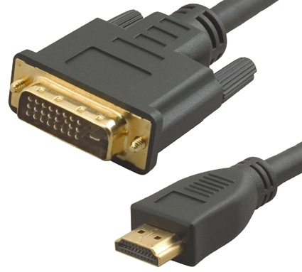
Adapter HDMI / DVI.
Dictionary
- HDMI = High Definition Multimedia Interface
Internal interfaces located in the PC case
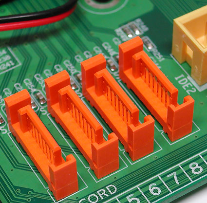
Four SATA ports on the motherboard.
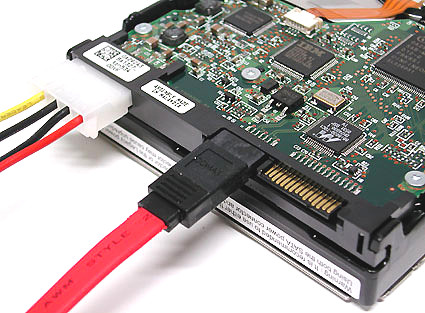
SATA is a serial interface for connecting drives (today they are mostly hard drives) and is intended to replace the old ATA parallel interface. The first-generation Serial ATA standard is widely used today and provides a maximum data transfer rate of 150 Mbps. The maximum cable length is 1 meter. SATA uses a point-to-point connection when one end of a SATA cable is connected to the PC's motherboard and the other to the hard disk. Additional devices are not connected to this cable, unlike parallel ATA, when you can hang two drives on each cable. So the master and slave drives are a thing of the past.

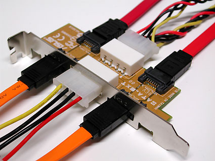
Many SATA cables come with caps that protect sensitive contacts.
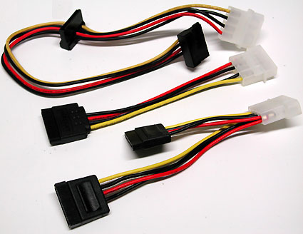
Power SATA in different formats.

This is how SATA hard drives are powered.
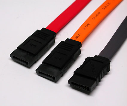
Cables come in a variety of colors.
Although SATA was designed for use inside a PC case, a number of products provide external SATA interfaces.
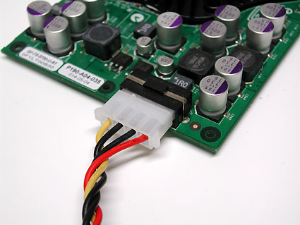
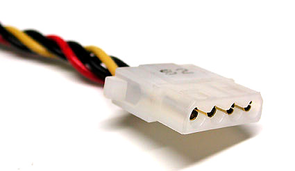
Powering SATA drives can be provided in two ways: through the classic Molex plug ...
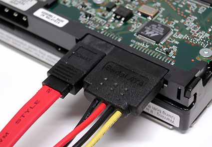
... or using a special power cable.
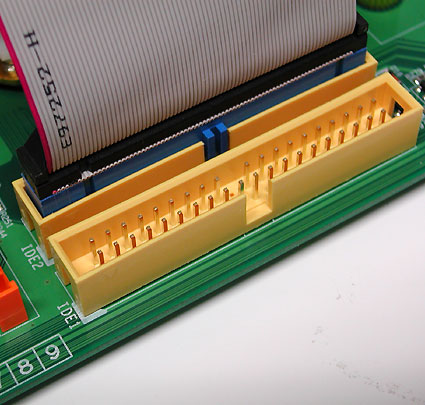
Parallel bus transfers data from hard drives and optical drives (CD and DVD) and back. It is known as parallel ATA (Parallel ATA) and today gives way to serial ATA (Serial ATA). The latest version uses a 40-pin wire with 80 wires (half to ground). Each such cable allows you to connect a maximum of two drives, when one works in the "master" mode, and the second - in the "slave". Usually the mode is switched using a small jumper on the drive.

IDE ribbon cable.

Connecting DVD-ROM drive: a red strip on the cable should always be located next to the power connector.
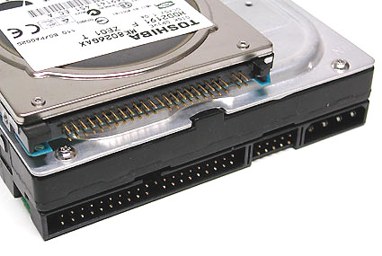
ATA / 133 interface for classic 3.5 "hard disk (bottom) or 2.5" version (top).
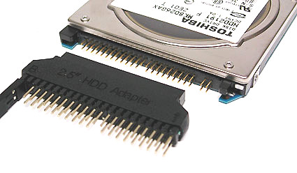
If you want to connect a 2.5 "drive for laptops to a regular desktop PC, you can use the same adapter.
Warning: in most cases, it is impossible to connect the interface incorrectly because of the protrusion on one side, but it may not be present on old cables. Therefore, follow the following rule: the end of the loop marked with a color bar (most often red) should always coincide with pin number 1 on the motherboard, and should also be closer to the power connector of the CD / DVD drive. To prevent improper connection, many cables and connectors do not have one pin leg or pin hole in the middle.
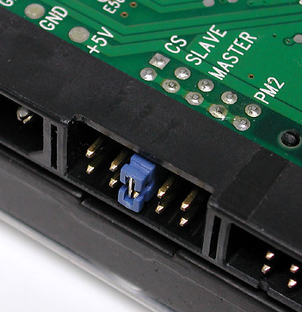
One cable supports the connection of two devices: say, two hard drives or a hard drive paired with a DVD-drive. If two devices are connected to the loop, one should be configured as "master" and the other as "slave". To do this, you have to use the jumper. Usually it is set to one or another setting. If in doubt, refer to the documentation (or the website of the drive manufacturer).
Dictionary
- ATA = Advanced Technology Attachment
- E-IDE = Enhanced Integrated Drive Electronics
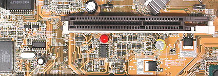
An AGP slot with a snap for a graphics card.
Most graphics cards in custom PCs use the Accelerated Graphics Port (AGP) interface. The oldest systems use the PCI interface for the same purpose. However, PCI Express (PCIe) is intended to replace both interfaces. Despite the name, PCI Express is a serial bus, and PCI (without the Express suffix) is parallel. In general, PCI and PCI Express buses have nothing in common besides the name.

AGP graphics card (top) and PCI Express graphics card (bottom).

Motherboards for workstations use an AGP Pro slot, which provides extra power for voracious OpenGL cards. However, it is possible to install into it also usual graphic cards. However, AGP Pro has not received widespread acceptance. Typically, voracious graphics cards come with an additional power socket — for the same Molex plug, for example.
Additional power for the graphics card: 4- or 6-pin socket.

Additional power for the graphics card: Molex jack.
The AGP standard has experienced several updates.
| Standard | Bandwidth |
| AGP 1X | 256 MB / s |
| AGP 2X | 533 MB / s |
| AGP 4X | 1066 MB / s |
| AGP 8X | 2133 MB / s |
If you like to dig in the "iron", then you should remember two levels of interface voltage. AGP 1X and 2X standards work at 3.3 V, while AGP 4X and 8X require only 1.5 V. In addition, there are Universal AGP cards that are suitable for any type of connector. To prevent erroneous card insertion, AGP slots use special protrusions. And the cards are slotted.
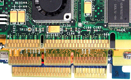
The top card has a slot for AGP 3.3 V. In the middle: a universal card with two notches (one for AGP 3.3 V, the second for AGP 1.5 V). Below is a map with a notch on the right for AGP 1.5 V.
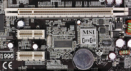
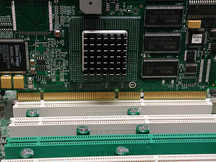
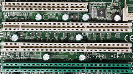
Motherboard expansion slots: PCI Express x16 lines (top) and 2 PCI Express x1 lines (bottom).

Two PCI Express slots for installing two nVidia SLi graphics cards. Between them you can see a small PCI Express x1 slot.
PCI Express is a serial interface and should not be confused with PCI-X or PCI buses that use parallel signaling.
PCI Express (PCIe) is the most advanced interface for graphics cards. At the same time, it is also suitable for installing other expansion cards, although there are very few of them on the market yet. PCIe x16 provides twice the bandwidth than AGP 8x. But in practice this advantage didn’t manifest itself.
AGP graphics card (top) versus PCI Express graphics card (bottom).

From top to bottom: PCI Express x16 (serial), two interfaces parallel PCI and PCI Express x1 (serial).
| The number of lines PCI Express | Throughput in one direction | Total bandwidth |
| 1 | 256 MB / s | 512 MB / s |
| 2 | 512 MB / s | 1 GB / s |
| 4 | 1 GB / s | 2 GB / s |
| 8 | 2 GB / s | 4 GB / s |
| 16 | 4 GB / s | 8 GB / s |

PCI is a standard bus for connecting peripheral devices. Among them are network cards, modems, sound cards and video capture cards.
Among motherboards for the wide market, the PCI bus of 2.1 standard, operating at 33 MHz and having a width of 32 bits, is the most common. It has a capacity of up to 133 Mbit / s. The manufacturers didn’t accept the PCI 2.3 bus with a frequency up to 66 MHz. That is why there are very few maps of this standard. But some motherboards support this standard.
Another development in the world of parallel PCI bus is known as PCI-X. These slots are most often found on motherboards for servers and workstations, since PCI-X provides higher bandwidth for RAID controllers or network cards. For example, the PCI-X 1.0 bus offers bandwidth up to 1 Gbit / s with a bus frequency of 133 MHz and 64 bits.
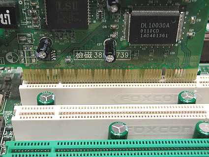
The PCI 2.1 specification today provides a 3.3V supply voltage. The left cut-out / overhang prevents the installation of old 5-B cards, which are shown in the illustration.

Card with a cut, as well as a PCI slot with a key.
RAID controller for a 64-bit PCI-X slot.
Classic 32-bit PCI slot at the top, and three 64-bit PCI-X slots at the bottom. Green slot supports ZCR (Zero Channel RAID).
Dictionary
- PCI = Peripheral Component Interconnect
The following table and illustrations show the different types of power connectors.
Standard power connector.
| AMD | |
| Socket 462 | |
| Power standard | ATX12V 1.3 or higher |
| ATX plug | 20 pin |
| AUX plug (6 pin) | Not used |
| Rarely used | |
| Socket 754 | |
| Power standard | ATX12V 1.3 or higher |
| ATX plug | |
| AUX plug (6 pin) | Not used |
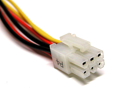
| P4 connector (4 pin 12 V) | Sometimes present |
| Socket 939 | |
| Power standard | ATX12V 1.3 or higher |
| ATX plug | 20-pin, sometimes 24-pin |
| AUX plug (6 pin) | Not used |
| P4 connector (4 pin 12 V) | Sometimes need |
| Intel | |
| Socket 370 | |
| Power standard | ATX12V 1.3 or higher |
| ATX plug | 20 pin |
| AUX plug (6 pin) | Rarely used |
| P4 connector (4 pin 12 V) | Rarely used |
| Socket 423 | |
| Power standard | ATX12V 1.3 or higher |
| ATX plug | 20 pin |
| AUX plug (6 pin) | Rarely used |
| P4 connector (4 pin 12 V) | Need |
| Socket 478 | |
| Power standard | ATX12V 1.3 or higher |
| ATX plug | 20 pin |
| AUX plug (6 pin) | Not used |
| P4 connector (4 pin 12 V) | Need |
| Socket 775 | |
| Power standard | ATX12V 2.01 or higher |
| ATX plug | 24-pin, sometimes 20-pin |
| AUX plug (6 pin) | N / A |
| P4 connector (4 pin 12 V) | Need |
| P4 connector (8 pin 12 V) | This 945X chipset with dual-core CPU or higher support needs this connector. |
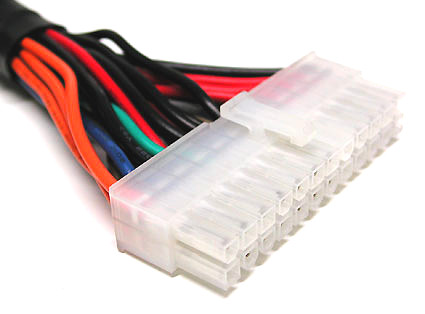
ATX 24-pin plug (Extented ATX).
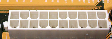
ATX 20 pin motherboard plug
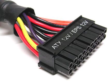
20 pin ATX cable.
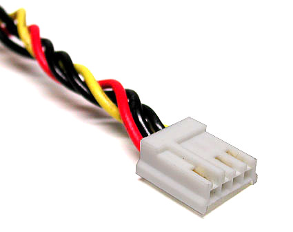
6 pin EPS connector.
Came and went: drive power connector.
20/24 pin connector (ATX and EATX)
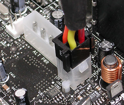
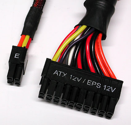
Do not do this. A 4-pin extender from 20 to 24 pins on the ATX plug cannot be used for the 12-V auxiliary AUX connector (however, it is too far away). The 4-pin extender is designed for the Extended ATX port and is not used on 20-pin ATX motherboards.
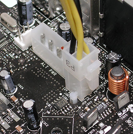
Here's how: a separate 4-pin plug is inserted into the 12-AUX port. It is easy to recognize: two golden and two black cables.
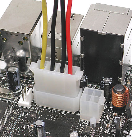
Many motherboards require an additional power supply.