Uninterruptible Power Supplies Off-Line
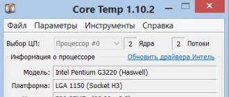
Uninterruptible power supplies of type Off-Line are defined by the standard as passive, standby actions (UPS -PSO). In normal mode of operation, the standard power supply of the load is the filtered voltage of the primary network with permissible deviations of the input voltage and frequency. In cases where the parameters of the input voltage go beyond the values \u200b\u200bof the configured ranges, the inverter of the uninterruptible power supply is turned on, ensuring the continuity of the power supply to the load. The inverter is powered by batteries.
These are the simplest UPSs (Figure 1), and therefore the cheapest. The uninterruptible power supply consists of two parallel branches:
... filter load;
... rectifier-battery-inverter-load.

Fig. 1. Stand-By type uninterruptible power supply circuits
Under normal network characteristics, the voltage is supplied to the load through a filter that filters all kinds of interference. This is usually a surge suppressor, although it can be a line conditioner or a combination of both, and a static switch.
At the same time, the accumulator batteries are recharged through the rectifier. When the input voltage is lost, overestimated or lowered, the power supply of the load by an electronic switch is switched to the battery through the inverter (the inverter converts the DC voltage into AC). The switch provides switching times from 2 to 15 ms. Note that power outages during this time do not have any noticeable effect on computer systems that can easily tolerate a 10-20ms power outage. Considering that almost all modern equipment has impulse power supplies, switching is performed imperceptibly for the user. Uninterruptible power supplies of this type can support the operation of a personal computer for 5-10 minutes.
Main Disadvantages of Off-Line UPS
The main disadvantages of off-line UPS are:
... poor performance of power supplies of this type in networks with poor quality electrical network: poor protection against voltage dips (sags), overvoltage, changes in frequency and waveform of the input voltage;
... impossibility of timely restoration of battery capacity with frequent switchings to battery power;
... non-sinusoidal output voltage when powered by a battery.
Line-Interactive uninterruptible power supplies
Line-interactive uninterruptible power supplies (Line-Interactive, sometimes Ferroresonant) combine the advantages of the On-line type with the reliability and efficiency of standby ones. In uninterruptible power supplies of this type, in contrast to the Off-line technology, a step automatic voltage regulator (booster), built on the basis of an autotransformer (transformer with switching windings), is included in the direct circuit. Some models use a network voltage stabilizer.
The inverter is connected to the load. In operation, it supplies the load in parallel with the conditioned AC mains voltage. The load is only fully connected when the mains input voltage is lost.

Fig. 2. Line-Interactive type uninterruptible power supply circuits
Because of this "interaction" with the input mains voltage, this architecture got its name. In a certain range of mains voltage variation, the output voltage is maintained within the specified limits by switching the transformer windings or by a stabilizer. The inverter typically operates at low voltage, regulates the output voltage and recharges the batteries until it needs to be turned on to fully power the load in the event of a power outage. Line-interactive uninterruptible power supplies are most widely used in computer network protection systems.
The transformer, made according to a special so-called ferro-technology, smoothes out voltage surges, while the uninterruptible power supply switches to battery operation less often, and therefore increases the battery life. Usually, these uninterruptible power supplies are equipped with sophisticated filters to provide protection against interference of various origins. Typical switching times to or from battery power are 2 ms.
Structurally, the transformer does not have several additional taps in the secondary winding (it can be an autotransformer with a single winding), the controller (microprocessor) controls the switching of the taps of the transformer when the input voltage changes, maintaining the output voltage in the required range. So, Line-Interactive uninterruptible power supply works on the principle of controlled LATR and really less often switches to battery power during input voltage surges. In this scheme, the charger is structurally combined with the converter.
One of the advantages of this type of UPS is the wide range of permissible input voltages.
In some line-interactive models, there is a shunt circuit between the mains input and the load, such UPSs are called line-interactive shunt UPS (UPS -LIB, Reversible + Bypass). In shunt mode, the supplied load is not protected. When working with sources based on ferro technologies, you need to keep in mind:
Uninterruptible Power Supplies On-Line Type
On-Line technology allows you to implement the most reliable type of uninterruptible power supply. From the rectifier (Figure 3), the mains voltage is supplied to the DC voltage converter high level to low ПН1, and then - to the converter of constant voltage to variable output voltage (ПН2). Converter PN2 is an inverter, the power to which is supplied both from the batteries and from the network through the voltage rectifier-converter PN1, connected in parallel:
.
at normal input AC voltage, the PN2 inverter is powered from the rectifier;
... in case of deviations in the supply network from the norm, the input voltage for PN2 is removed from the storage battery.

Fig. 3. On-Line Type Uninterruptible Power Supply Circuits
In most systems of uninterruptible power supplies with a capacity of up to 5 kVA, instead of a continuously connected battery, a backup DC-DC converter (DC-DC converter) is connected, which turns on in case of mains failures and duplicates the DC bus from the low-voltage battery.
Conclusion: even in cases of slight deviations of the input voltage parameters from the norm, On-Line devices provide a rated output voltage in the range of ± 1-3%. The presence of a bypass circuit allows the load to be connected directly to the mains. The power quality and reliability of power supply provided by devices with this type of architecture is significantly higher than that of the previous ones.
Disadvantages of On-line uninterruptible power supplies: low efficiency (85 -90%) compared to the previously discussed types due to double conversion (in relation to Standby and Line-Interactive) and high price. However, the level of protection of the load and the stability of the UPS output parameters are a reasonable compromise between safety, efficiency and cost of the device. Losses in a 4000VA UPS do not exceed 380W and can be incommensurate with the task that such a power source solves.
New modifications of uninterruptible power supplies
Now there are several new modifications of uninterruptible power supplies:
.
by-pass;
... triple-conversion;
... ferrups.
The first modification (by-pass), as in Figure 3, is an additional channel for transmitting electricity to the load, its presence allows to ensure high reliability of the device. Switching to the On-line mode is performed automatically when the parameters of the output network deviate from the norm or in emergency conditions. Thus, this mode helps to increase the reliability of the device. The second modification (triple-conversion) contains a power factor corrector. In the third modification (ferrups), a ferroresonant transformer is used, which provides high reliability rates and a wide range of input voltages.
New approaches in the construction of uninterruptible power supplies are based on the use of redundant power systems, which have a higher reliability of the output network, so that a failure of one of the elements does not lead to the failure of the entire system. Typically, these are modular systems, designed either to increase load power, or to improve system reliability, or using both principles together. The simplest system has an auxiliary module in the structure of the uninterruptible power supply, "isolated in hot standby mode". There are several options for technical solutions for such UPS.
The first option is to use an automatic switch (Figure 4). The inputs of one or more power supplies are connected to a single network, and are connected to the load through an automatic switch. Information about the state of the units operation, control commands are received via the communication channel of the integrating UPS.

Fig. 4. Parallel circuit using automatic switch
The second option contains a “load distributor” (Figure 5), which evenly distributes the load between the individual sources of the system.

Fig. 5. Parallel circuit using automatic switch
The third embodiment of the parallel structure (Figure 6) uses the principle of a two-tier system. In this method, one of the "master" modules controls the load sharing between the other "slave" modules.

Fig. 6. Parallel circuit based on two-level Master-Slave system
The fourth option, with a redundant parallel architecture, looks the most promising. In such a scheme (Figure 7), not only modules are reserved, but also connections between them, and, if necessary, any module can act as a master. Only such a scheme is characterized by an increase in power, the absence of shunt circuits, while continuous protection of the load using a UPS is guaranteed.

Fig. 7. Redundant Parallel System Diagram
Main technical characteristics of uninterruptible power supplies
Supply voltage form
It is this characteristic of the uninterruptible power supply that is important for the load. In the UPS operation mode, the load can receive an output AC voltage close to a rectangular shape (meander), due to the smoothing properties of filters, an approximated sine wave and a pure sine wave. The closest to a sinusoidal output voltage waveform is obtained by applying pulse width modulation. Obtaining a sinusoid as a supply voltage is typical only for On-line UPS and some Line-Interactive power supplies.
Power
Full or output power.It is designated by the letter S, the unit is VA or Volt-Ampere. It is the geometric sum of active and reactive power. The parameter is calculated as the product of the rms (rms) values \u200b\u200bof current and voltage. Its value is indicated by the manufacturer of the power supply.
Active power consumption of the load. It is designated by the letter P, the unit of measure is watt (W). In the absence of a reactive component in the network, it coincides with the total power. It is defined as the product of the total power and the cosine of the angle φ, where φ is the phase angle of the linear voltage and current vectors, i.e. P \u003d S. cos (φ). Typical cos (φ) value for personal computers about 0.6-0.7. This quantity is called power factor. Obviously, to select the required power for an uninterruptible power supply, it is necessary to divide the load power in watts by the value of cos (φ).
Reactive - denoted by the letter Q and is calculated as the product of the total power S by the sine of the angle φ (Q \u003d S. Sin (φ)). The unit of measurement is reactive volt-ampere (var). It characterizes the losses in the supply wires due to the reactive current loading them. At cos (φ) \u003d 1, there are no losses, all the power generated by the power supply goes to the load. This is achieved through the use of passive compensating devices or active power factor correction.
Input supply voltage range
Input voltage range - defines the range of acceptable voltage values \u200b\u200bin the network, at which the uninterruptible power supply is still able to maintain the output voltage without switching to battery power. For some models, this range is load dependent. For example, at 100% load, the input voltage range can be 15-20% of the nominal, at 50% load - this range is 20-27% of the nominal, and at 30% load - 40% of the nominal. Battery life depends on this parameter, the wider the range, the longer the batteries will last, all other things being equal.
Input voltage frequency
Input frequency - characterizes the range of deviation of the mains frequency. Under normal operating conditions, the frequency deviation from the nominal value usually does not exceed 1 Hz.
Output voltage waveform distortion factor
The total harmonic distortion (THD) characterizes the deviation of the output voltage from the sinusoid, measured as a percentage. Small values \u200b\u200bof the coefficient correspond to the shape of the output voltage, approaching sinusoidal.
Mode switching time
The time of switching modes (transfer time) characterizes the inertia of an uninterruptible power supply, for different sources it is approximately up to 2-15 ms.
load) characterizes the stability of the uninterruptible power supply during power overloads, measured as a percentage in relation to the rated power. Determines the resistance of the UPS to transient overloads.Battery life
Battery life is determined by battery capacity and load size. For typical low-power uninterruptible power supplies supplying personal computers, it is 5-10 minutes. This time is calculated so that the user can close all running applications while saving the information and turn off the PC in normal mode.
Crest factor
The crest factor is the ratio of the peak value of the consumed current to the average current. The value depends on the shape of the supply voltage.
Battery life
The service life of rechargeable batteries is 4-5 years, but the real one strongly depends on the operating conditions: the frequency of switching to autonomous mode, charging conditions, and the environment.
Cold start
The presence of a cold start is the ability to turn on an uninterruptible power supply in the absence of voltage in the supply network. This function is useful when you need to urgently perform any action, regardless of the presence of voltage in the mains.
UPS batteries
General information
The source, the energy of which is used to power the load in critical operating modes, is a storage battery. In uninterruptible power supplies with a capacity of up to 20 kW, as a rule, sealed lead-calcium batteries with a suspension type electrolyte are used. In batteries of this type, the electrolyte is immobilized, either by silica gel or by glass fiber, which makes them leak-proof. This property of the electrolyte allows the batteries to be operated in any position; moreover, they do not need periodic electrolyte replenishment and other maintenance.
The electrodes are made of a lead-calcium alloy, which provides a long service life and a wide range of battery applications, the operating temperature range is from minus 20 to plus 50 ° C (for some types of batteries). Batteries do not suffer from the so-called "memory effect", they can be stored for a long time in a charged state (up to a year), while the self-discharge current is insignificant.
Battery design
The design of the batteries is traditional - the shock-resistant plastic case is divided into sections - "banks". The sets of cathode and anode plates are separated by spacers - fiberglass separators. The active part of the electrolyte is sulfuric acid. The cover is sealed to the body, without the possibility of disassembling the battery. In the upper part of the cover, there are valves (one for each section), which ensure the release of gas in the event of its excessive formation during operation, and plate outlets. The valves are closed with an additional removable cover.
Battery storage
The battery life is approximately 5 years. With daily use of an uninterruptible power supply, the inherent charging capabilities guarantee operation during this period Batteries self-discharge if left unused. For YUASA batteries, the self-discharge rate is approximately 3% per month at an ambient temperature of approximately 20 ° C. If the batteries are not charged during a long period of time, lead sulfates form on the negative plates of the battery. This phenomenon is known as "sulfation". Lead sulfate acts as an insulator, preventing the battery from accepting charge. The deeper the plate is softened, the less charge the battery can take.
In order to exclude irreversible consequences during storage, the charge must be carried out after a period corresponding to the ambient temperature conditions. Long-term storage batteries should be recharged periodically to ensure optimal life.
UPS battery charging methods
Battery charging is a major part of its maintenance. The battery life depends on the efficiency of the selected charging method. The following charging methods are available:
- charging at constant voltage;
- charging at constant amperage;
- two-stage constant voltage charging.
The preferred method is constant voltage charging. In this case, the battery is connected to an energy source, the charging voltage of which is kept constant during the entire charging process. In the course of charging, the current decreases and becomes much less than when charging with a constant current method, and at the end of the charge it drops to almost zero. In this case, the battery is charged to 90-95% of its nominal capacity.
Choosing an uninterruptible power supply
The range of types of uninterruptible power supplies as a means of protecting equipment and computer systems is quite wide. The choice of the required power source is very difficult. To decide the issue of choosing one or another UPS, you need to try to analyze the factors that affect the operating conditions of the power source.
First, one should try to assess the significance of the system being fed. It is quite possible that an Off-line or Line-interactive type uninterruptible power supply will be sufficient for a home or office option. On-line UPS is more suitable for a server computer and other types of load that have increased requirements for the quality and reliability of power supply.
Secondly, it is necessary to assess the quality of the power grid: the probability and frequency of voltage outages, the presence of voltage fluctuations and various interference.
Third, you need to evaluate the capacity of the uninterruptible power supply. In order to roughly imagine what power of the UPS is required, it is necessary to determine the protected equipment and calculate the total value of the consumed power for it. Then, the watts obtained must be converted to VA, divided by the power factor. For computer equipment, the power factor is 0.5-0.6.
Manufacturers do not recommend loading an uninterruptible power supply more than 80% of the maximum load. It should be noted that laser printers it is not recommended to connect to an uninterruptible power supply due to the high energy consumption of the heating element.
Electrical vibrations and their characteristics
Classic electrical vibrations, arising for example in an oscillatory circuit or at the output of a generator alternating currentare harmonic. This means that the dependence of the intensity of the oscillation (instantaneous value of voltage or current) on time can be represented graphically in the form of a sinusoid.
In real life, the waveform of a voltage or current may deviate slightly from a pure sine wave. Let's see what parameters the electrical oscillatory process is characterized by.
Figure: 21. Parameters of electrical oscillations
Amplitude value or amplitude is the maximum deviation of the fluctuating value from the zero level.
The effective value of the current or voltage is numerically equal to that direct current or direct current voltage that produces the same thermal effect in the conductor. The effective value of the voltage or current is equal to the root-mean-square value of the corresponding value over the period of oscillation.
The crest factor or crest factor is the ratio of the amplitude of the oscillation to its effective value. It is always greater than or equal to 1. For a harmonic oscillation (sinusoidal voltage or current), the crest factor is \u003d 1.41 (more precisely, the root of two). The crest factor of non-sinusodal oscillations can be very different from this value.
The crest factor characterizes non-sinusoidal oscillations not uniquely. Oscillatory processes of different shapes can have the same amplitude coefficients.
In order to fully characterize a complex periodic oscillation, it is artificially presented as a sum of several harmonic oscillations of multiple frequencies (harmonics). So, for example, in order to describe a nonsynsoidal process with a fundamental frequency (first harmonic) equal to 50 Hz, it is represented as a sum of oscillatory processes with frequencies of 50 Hz, 100 Hz (second harmonic), 150 Hz (third harmonic), etc. .d.
The analysis of a complex oscillation carried out in this way is called harmonic analysis or Fourier analysis (named after the French mathematician and physicist). The result of harmonic analysis is the so-called spectrum of the oscillatory process - the dependence of the intensity of each harmonic on its number.
In fig. 22 shows an arbitrary oscillatory process and the beginning of its spectrum.

Figure: 22. Electrical vibration and its spectrum.
For an accurate representation of a complex waveform, at least several tens of harmonics must be considered.
As an integral characteristic of the degree of difference of the form of the oscillatory process from the sinusoid in Russia, the harmonic distortion coefficient (harmonic distortion) is often used - Kg. It shows how much of the energy is contained in the higher harmonics, compared to the energy contained in the first harmonic.
In other countries, for this they usually use the total harmonic distortion factor (English: total harmonic distortion factor - THDF). It shows what proportion of energy is contained in the stash harmonic in comparison with the total energy of the vibration.
It is clear that with almost sinusoidal processes Kr and THDF are practically equal. But with significant distortions, they differ. The table lists several points that characterize this difference.
| Kg,% | THDF,% |
| 0 | 0 |
| 10 | 10 |
| 20 | 20 |
| 30 | 29 |
| 40 | 37 |
| 50 | 45 |
| 60 | 51 |
| 70 | 57 |
The harmonic distortion coefficient of a purely sinusoidal oscillatory process is zero (all energy is contained in the fundamental harmonic). It is usually considered that the oscillation is slightly different from the sinusoidal, if the harmonic distortion does not exceed 5%.
Linear and non-linear loads
If we connect a resistor to the DC voltage source and change the voltage value, the current flowing in the circuit will change in proportion to the voltage.
If we connect to a sinusoidal alternating voltage source (for example, to the mains or to UPS with a sinusoidal output voltage) resistor, the instantaneous value of the current in the circuit will be proportional to the instantaneous value of the voltage. Consequently, the current in the circuit will be sinusoidal, with a common-mode voltage (i.e., the maximum current values \u200b\u200bwill be observed exactly at the same time moments as the maximum voltage values.

Figure: 23a. Current consumption of the resistor in the AC circuit.
If we connect capacitance, inductance, or any combination of them with resistors to the sinusoidal voltage source, the current in the circuit will still be sinusoidal (see Figure 23b).

Figure: 23b. The current consumption of the capacitive load in the AC circuit.
But in this case, the current peaks will be ahead of the voltage peaks (as in the figure) or lag behind them. Depending on the predominance of capacitors or inductors in the circuit, such a load is called ecoste or inductive. And in the aggregate, all loads (electricity consumers) with sinusoidal current consumption (with sinusoidal voltage) are called linear.
A switching power supply (such as a computer) is a non-linear load. If the computer is connected to a sinusoidal voltage source, then the dependence of the current consumed by the computer on time will have the form shown in Fig. 23c.

Figure: 23c. Non-linear load current consumption in the AC circuit.
The figure clearly shows that the computer consumes current only at moments when the voltage is close to its maximum, and does not consume current at low voltage.
The shape of the current consumed by a non-linear load can be characterized by the same parameters as any oscillatory process.
Crest factor
The crest factor (crest factor) of the current consumption of switching power supplies is always much greater than unity. It usually ranges from 2 to 3, but it can be more than 5.
An uninterruptible power supply must be sized to handle these peak factors. Those. UPS should not only provide the effective current value corresponding to the maximum load, but also the maximum (peak) current value, significantly exceeding the amplitude of the sinusoidal current with the same effective value.
The crest factor is not a constant characteristic of the power supply. It is a product of the interaction of the power supply, its load (for example, a computer) and the current source to which it is connected. So, when powered from the network, it can be equal to 2 or 3. If the computer is powered by UPS with switching, having an output voltage in the form of a square wave with a pause, the crest factor is reduced to 1.8-2. Connecting a computer to a ferroresonant transformer can reduce the crest factor even more. This reduces the load on the computer's power supply and increases its longevity.
On the other hand, if the computer's power supply is left idling or with a very small load (for example, take a 400 W power supply and put it in a simple staff of minimum power), then the current crest factor can be very high (for example 5). If the same power supply unit is fully loaded (say, install it in file server with large disks, modems, etc.), the crest factor will decrease (and will be for example 2.5).
Harmonics
In fig. 24 shows an exemplary view of the current spectrum of a switching power supply. Rather, it is the beginning of the spectrum. The full current spectrum of a switching power supply includes many tens of harmonics.

Figure: 24. The beginning of the spectrum of the current pulse power supply.
In the current consumption of the switching power supply, there is a set of odd harmonics, the amplitude of which decreases more or less monotonically with the harmonic number.
If computers are connected to an electrical network, which also includes other (and, mainly, linear) consumers of electricity, then the difference in the shape of the current consumed by the computer's power supply from the sine wave does not affect either the computers themselves or other equipment connected to the same electrical network.
If computers are mainly connected to the network and their total power is comparable to the characteristic power of the electrical network, then the voltage in the network may cease to be sinusoidal. This is a sign of overloading the electrical network with non-linear loads, and can cause malfunctioning of sensitive equipment.
The first sign of network overload with computer loads is the manifestation of the most intense - the third harmonic. Its appearance can be determined without even having a spectrum analyzer capable of constructing a beautiful picture, like the one shown in Fig. 24. A simple oscilloscope is sufficient for elementary analysis.
If a sinusoid has a flat top (as if "eaten away" by a large pulse current), this is the first sign: a third harmonic has appeared in the network, the network is slightly overloaded with nonlinear loads.
If the top of the sinusoid begins to sharpen, then, in addition to the third harmonic, the fifth harmonic has appeared in the network: the network is heavily overloaded with nonlinear loads.
If waves appear on the sinusoid, then the seventh harmonic is already visible with the naked eye: you need to take some measures.
UPS output voltage waveform
An uninterruptible power supply is a temporary substitute for the electrical network for the equipment connected to it. The quality of this replacement is highly dependent on the type and brand of the UPS.
In an electrical network, the voltage has a sinusoidal shape or a shape close to a sinusoid.
All upscale UPSalso have a sinusoidal output signal, i.e. provide power supply practically the same as a regular network or even have a higher quality sine wave.
At the exit UPS (as in the network) a sine wave may not be entirely perfect.
Determining harmonic distortion usually requires specialized equipment. But you can roughly estimate the value of the total harmonic distortion simply from the voltage oscillogram. If you see low distortion, the THD is around 5%. If distortion is very noticeable, the THD is approximately 10%.

With a harmonic distortion factor of more than 20%, you "do not raise your hand" to call the voltage waveform a sinusoid.
This method, like any simplification, has its limitations. In particular, the higher the harmonic number, the lower the harmonic distortion, it is clearly visible.
Sinusoidal output voltage is all UPS double conversion, ferroresonant UPS and most UPSinteracting with the network. For all these UPSthe total harmonic distortion of the output voltage, equal to 5%, is the boundary. If the output harmonic distortion is UPS less than 5%, then UPS this parameter can be considered "good". If this value is greater than 5%, then the output waveform UPS leaves much to be desired.
Usually manufacturers indicate the degree of harmonic distortion in the general list of technical specifications. UPS... There is almost always only one harmonic distortion value indicated, which refers to some average (if not ideal) conditions - for example, linear load. It should be borne in mind that the most significant distortions of the output voltage shape can occur under various boundary conditions, as well as with parameters not typical for routine work UPS.
Such limiting conditions (their set or combination may be different for different models UPS) there can be maximum load or idle (no load); limiting or exorbitant power factor (for example, less than 0.5), too large a crest factor. The output voltage can also undergo serious distortion during various transients (for example, when the load is stepped).
On line mode UPS with switching and interacting with the mains supply its load with filtered mains voltage. That is, in this case they are not independent power supplies. This source is the electrical network. This means that the harmonic distortion at the input of the computer's power supply will be approximately the same as without UPS. This is because the filters of these UPS are not designed to filter low-frequency harmonics, and they are freely passed. Accordingly, if there were strong harmonic distortions in the network before installation UPS (due to general network overload or a large share of the power of non-linear loads), they will remain so. If these distortions were not there, they will not appear.
The situation is different with ferroresonant UPS and UPS with double energy conversion. They are, in this sense, independent power supplies. Therefore, all that has been said above regarding the distortion of the mains voltage shape must in this case be attributed to the output voltage UPS... If these UPS heavily (almost to the rated power) are loaded with non-linear loads, then fundamental harmonic distortions may appear at the input of these loads, which were not without UPS... On the other hand, if harmonic distortions were observed during mains operation, they may disappear after installation. UPS, if a UPS underutilized.
is more than two-thirds of its full power, then the output voltage UPSmay be noticeably distorted. Distortion of the voltage waveform, which is not dangerous in itself for computers, is not a good sign that the load UPS too big. Better to install UPShigher power or disconnect any equipment from it.Some upscale UPS from double conversion equipped with a special control circuit, the purpose of which is to correct the shape of the output voltage, even when working with non-linear loads of high power. Out of these UPS voltage has no appreciable harmonic distortion, even if UPS supplies high power non-linear loads.
Of course, all computers and other equipment designed to be powered by AC power are rated for sinusoidal voltage. It is unlikely that any manufacturer of this technology is ready to guarantee the normal operation of its equipment with highly non-sinusoidal voltage.
However, most consumers of electrical energy can be supplied with non-sinusoidal AC voltage. Moreover, for different equipment, different characteristics of the sinusoidal supply voltage are more important. For example, equipment equipped with switching power supplies (say, personal computers) draws current only at times when the voltage is very close to maximum. Therefore, for powering such equipment, the correct amplitude value of the voltage is important. Equipment containing directly powered electric motors and heaters requires rated rms voltage. The sinusoidal voltage meets the requirements of any of these loads.
But almost all types of loads (equipment), including computers, can work more or less normally with a voltage that is very different from sinusoidal. This circumstance is widely used by manufacturers UPS with switching.
Earlier (very long ago) some UPS with switching had an output voltage in the form of a meander (rectangular pulses of different polarity).

Figure: 26. Meander
When we replace a sinusoidal voltage with one or another of its approximations, we must choose the parameters of this approximation so that they are closest to the parameters of the replaced sinusoid. But in a meander, the amplitude and effective voltage values \u200b\u200bare equal to each other (the crest factor is equal to one). Therefore, we cannot make the rectangular stress so that it simultaneously satisfies the requirements of different loads.
In an attempt to find a compromise, manufacturers of such UPS set the rectangular voltage equal to some value lying between the amplitude and effective. As a result, it turned out that some loads (requiring the correct RMS voltage) could fail due to overvoltage, while other equipment (drawing current at voltages close to the maximum) this voltage was too low.
In order for the rms and peak values \u200b\u200bof the rectangular voltage to be equal to the corresponding values \u200b\u200bof the sinusoidal voltage, manufacturers of modern UPS with switching, we slightly changed the shape of the meander, introducing a pause between rectangular pulses of different polarity.

Figure: 27. Meander with a pause.
Voltage of this shape manufacturers UPS called "stepped approximation to a sine wave". This curve shape allows, with correctly selected voltage amplitude and pause duration, to meet the requirements of different loads. For example, with a pause duration of about 3 ms (for a frequency of 50 Hz), the effective voltage value coincides with the effective value of the sinusoidal voltage of the same amplitude.
The output voltage of everyone I came across UPS with switching, present on the Russian market, has the form of a stepwise approach to a sinusoid.
Shown in fig. 27 the output voltage waveform is the ideal that UPS manufacturers should strive for. Real form of output voltage UPS with switching is certainly not ideal.
Sometimes manufacturers UPScomply with the declared equality of the effective value of the output voltage UPS the rms value of the mains voltage is very approximate. The duration of the pauses and the amplitude of the rectangular voltage deviate noticeably from the calculated values.
These deviations apparently cannot serve as a basis for declaring this or that UPS bad. After all, they all work normally with personal computers, for which they are actually intended to work.
Real form of output voltage UPS with switching is shown in fig. 28.

Figure: 28. Oscillograms of voltage and current of a personal computer connected to UPS with switching.
The same oscillogram also shows the curve of the current consumed by the computer. This allows you to assess how "hard" it is for the computer being protected UPS with switching. But, oddly enough, strong impulse currents consumed by the computer at the moments of the beginning and end rectangular pulsedo not affect the operation of the computer. They are completely suppressed by the computer's power supply, the output of which is a constant voltage with a normal level of ripple.
It should also not be forgotten that the computer being protected UPS with switching, powered by non-sinusoidal voltage only during operation UPS from the battery (i.e. very shortly). At work UPS from the mains, the computer is powered by the mains voltage, smoothed using the built-in UPS filters of noise and impulses.
Applicability UPS switching to power other equipment (not computers) requires, generally speaking, verification in each such case. There are cases when with such UPS some printers refused to work. On the other hand, a case of application is known UPS switchable to protect unconventional loads such as telephone exchanges or cash registers with transformer power supplies.
For application UPS with switching to supply devices with transformer power supplies should be approached with care. The fact is that the 5-10% losses typical for a transformer in the presence of harmonics increase in proportion to the square of the number of agarmonics. Therefore, the resource of heavily loaded transformers when supplied with voltage in the form of a meander can be reduced tenfold.
As with any power supply, the output voltage waveform UPS with switching depends on the size and nature of the load. For UPS, produced by well-known firms in the world, this dependence is usually small.
However, some UPS have a strong dependence of the shape (and sometimes the amplitude) of the output voltage on the load. Some of them cannot be used at low loads, since they have a pulse voltage at the output with an amplitude of up to 800 V. Others are checked by the manufacturer only when working with linear loads. Such UPS when working with a computer may be unstable at the moments of switching.
The above shows: should not be used UPS unfamiliar manufacturers or buy such UPS from non-specialized firms.
Voltage stabilization and regulation
According to the current standard in Russia, the voltage in the electrical network must be within +10% and -10% of the rated voltage. For a voltage of 220 V, these limits have absolute values \u200b\u200bof 198 V and 242 V. In this voltage range, all equipment powered by the mains should work normally, from a light bulb to a computer.
Unfortunately, sometimes the tension goes beyond the limits set for him by the bosses. In some areas, such periods are repeated with the regularity of sunrise. Owners of computers operating under these conditions, of course, tend to require that UPSthe computers protecting them stabilized the voltage.
Two of the types of uninterruptible power supplies we've reviewed stabilize voltages, so to speak, by definition. it on-line UPS: double conversion and ferroresonant.
Output AC voltage stabilization accuracy UPS with double conversion, usually around 1-3% with static (i.e. constant in time) and balanced (evenly spaced for 3-phase UPS) load. In the case of a sharp change in the load (for example, its complete or incomplete switching on or off), the stabilization error increases to about 10% for good UPS... Not all manufacturers UPSindicate this characteristic. In the case when it is not indicated, you need to be very careful if work is of principle for you UPS under dynamic load.
With an unbalanced load (i.e. if the load is unevenly distributed over the phases 3-phase UPS) the stabilization error also increases. There are true three-phase UPS with independent voltage regulation in each of the three phases. Load imbalance for such UPS irrelevant.
The input voltage range, in which the voltage stabilization occurs, for UPS double conversion always matches the acceptable input voltage range (i.e. the voltage range at which UPS works from the network). In this way UPS double conversion can not help stabilize the voltage. It provides either a stable output voltage (when operating on mains or battery power) or none. Input voltage range for different UPSvaries greatly. The characteristic value is plus minus 10-15% of the nominal voltage. Some low power UPS can have an input voltage range from 100 to 280 volts and even wider (although often work UPS at minimum voltages only ensured at partial load).
If the user is not satisfied with the input voltage range, then for some models UPS it can be expanded with special tweaks. The expansion of the input voltage range (in those rare cases where it is possible) should be done by a very qualified person who has a very clear idea of \u200b\u200bwhat he is doing. It should be borne in mind that nothing is given for free, and in any case, you will have to pay something for expanding the input voltage range - for example, reliability UPS or the quality of the voltage supplied to the load.
For most Double conversion UPS the input voltage range depends on the load. With a lower load, the input voltage range expands somewhat.
Ferroresonant UPS stabilizes the voltage due to the properties of the ferroresonant transformer. Voltage stabilization error is 1-5% and depends on the load: at lower load, the error decreases.
The ferroresonant transformer is very resistant to any transients. Therefore, the stabilization error changes little under dynamic load.
The input voltage range of a ferroresonant UPS is highly dependent on the load. At low load, it can start from 145 V.
UPSwith switching do not have a voltage stabilization function.
UPS, interacting with the network, they can stepwise regulate the output voltage.
Step voltage regulation is implemented by switching the load to work from another winding of the autotransformer.
In the simplest case, there is only one step of increasing the voltage, which is triggered when the mains voltage decreases. More modern networking UPSregulate the voltage when it rises.
for instance UPS Smart-UPS American Power Conversion switches the load to autotransformer step-up winding when the voltage drops below 196 V. The step-up winding allows the voltage to be raised 12%. As the input voltage drops further, the output voltage drops linearly. When the input voltage reaches 176V ( factory setting) Smart-UPS
When the input voltage rises above 264 V, the load switches to operation from the autotransformer winding, which reduces the voltage by 12%. After the input voltage reaches 296 V, UPSswitches to battery operation.
Most UPSinteracting with the network, there is only one stage of voltage regulation (in each direction, if the regulation is two-way). But several UPS have two or more stages of stabilization in each direction.
Noise reduction
For protection against impulses in UPS different types different technologies are used. UPS switchable and mains-coupled suppress mains noise with R-C or L-C filters. In ferroresonant UPS the filter is a ferroresonant transformer. Suppressing noise in UPS double conversion is carried out in the process of two energy conversions. In addition, in the DC circuit of these UPS usually there are special capacitors and chokes to smooth out the ripple of the charging current. These L-C filters are very effective at suppressing noise that penetrates the rectifier.
Indicative levels of interference suppression in the frequency range from 1 to 10 MHz for different types of UPS are given in the table.
Pulse suppression
There are several standards in the world that describe the requirements for UPS, regarding protection against impulses. Usually American UPS are tested for compliance with ANSI / IEEE C62.41, which describes the impulse parameters that a computer or impulse protection equipment can withstand. The standard describes the voltage and pulse shape.
The standard provides two categories: A and B. Category A refers to typical office conditions and involves testing UPS by applying a 3000 V pulse to its input.Category B refers to more severe conditions (for example, for computers connected to the network near the power input to the building) and provides for a 6000 V pulse test.
Usually manufacturers UPS ensure that their products comply with Category A of this standard or an equivalent standard. Some UPS also comply with category B of the standard.
IN UPS different types of pulse suppression technologies are used. Varistor surge protection is used in UPS with switching and interacting with the network.
An obstacle in the path of the impulse through UPS with double conversion of energy is the double conversion itself, galvanic separation (in those models where it is) and the combination of capacities and batteries in the DC circuit. However, in some models Double conversion UPSadditionally installed varistor shunts.
In ferroresonant UPS the function of a pulse filter is performed by the ferroresonant transformer itself, although varistors are also available at the input UPS.
A very simple and effective varistor shunt can suppress pulses with high amplitude currents (kiloamperes for UPSwith switching and up to tens of kiloamperes for the best models UPSinteracting with the network).
For varistor protection, as already noted, there is a fundamental limitation of the pulse energy that the varistor shunt can withstand. Usually this energy is equal to 80-500 J. When a pulse of higher energy arrives at the varistor, it may fail. This can damage the varistor mechanically. This mainly limits the pulse duration, since the pulse amplitude can be quite large.
Another limitation of varistor protection is its resource. When the pulses are suppressed, the varistor gradually wears out and eventually breaks down.
Two other technologies of protection against impulses do not have a fundamental limitation of the resource and impulse energy. This, of course, does not mean that they can work forever and effectively suppress impulses of any amplitude and duration.
The task UPS is not only to withstand the impulse, but also to reduce its amplitude to an acceptable value for a computer. The table shows the approximate values \u200b\u200bof the pulse suppression ratio for different UPS... This coefficient is equal to the ratio of the pulse amplitudes without protection and when using protection. I am not aware of this value for a double conversion UPS.
Efficiency
Efficiency is not the most important characteristic UPS... If the computers being protected UPS do work, then the electricity they consume costs significantly less than the data stored in them. Therefore, the efficiency in itself cannot be considered as a parameter by which to choose UPS.
However, there are several important parameters related to efficiency that are worth discussing.
Efficiency is the ratio of the power consumed by the load UPS to the total consumed UPSpower. The higher the efficiency, the smaller the part passing through UPS power is released inside its body.
Extra heat generation inside the case UPS leads to a number of unpleasant consequences.
If you do not take additional measures to remove heat from the case (for example, fans), then the temperature inside UPS will rise. This will reduce the battery life. UPS(if installed inside). According to battery manufacturers, an increase in the operating temperature of a battery by 10 degrees leads to a decrease in its life by half.
Therefore all Medium and high power UPSwhich cannot be cooled by natural convection are equipped with forced cooling.
Low power UPS, built according to the scheme with double energy conversion, and ferroresonant ones, also have to be forcedly cooled, since they have the lowest efficiency, in comparison with other types we have considered UPS.
Efficiency value for Double Conversion UPS and Ferroresonant UPS (according to the manufacturers) is 85-94% at full power. If the load power is reduced to 70-80% of the nominal efficiency of modern uninterruptible power supplies, it hardly changes. It begins to drop noticeably only at an even lower load power.
IN recent times appeared UPS with an efficiency of at least 70-80% even at a power of about 30% of the nominal.
UPS with switching, interacting with the mains have approximately the same efficiency, since when operating on mains, the main power during operation of these UPScomes to the load with little or no conversion. Their efficiency when operating from the mains is at least 96% at full power mode and gradually decreases with decreasing load power.
Battery life
For most common office UPS low power battery life at maximum load is 4-15 minutes.
less than the maximum, the battery life is longer. Due to the non-linearity of the battery discharge curve, this increase is not proportional to the decrease in load. If the load is halved, then the operating time can increase by 2.5-5 times, if by three times, then the time increases by 4-9 times, etc.Determine exactly how much will work UPSat partial load, it is possible only experimentally or using the manufacturer's data. The following figure shows a graph by which you can roughly estimate this value.

Figure: 29. Working hours UPS from battery under load less than nominal
as a percentage of the nominal. The ordinate is the number of times the battery life is longer than the battery life at rated load. The figure shows the data of manufacturers for UPS more than 50 different power models from 250 to 18000 VA.The chart is very easy to use. If your computer has 50% of the rated power of your UPS, then, having found the appropriate division on the abscissa axis (horizontal axis), go straight up. At the intersection with the middle of the point cloud, you will find the value you need: run time UPSfrom the battery will increase by about 3.5 times.
Battery life is usually based on a new and fully charged battery. The characteristics for a worn-out battery will be completely different. We can only say that the operating time from a worn out or not fully charged battery will be shorter.
UPShigh power and some UPSlow power have the ability to increase the battery life by replacing the battery with a battery with a larger capacity or installing an additional battery.
A battery with a larger capacity can be installed in the same housing, or an additional battery housing can be installed.
If the battery capacity UPS increases, and the power of its charger remains the same, then the battery charging time increases. When the battery capacity is increased several times, the charging time increases by about the same amount.
Some manufacturers UPS provide for the possibility of replacing the charger with a more powerful one. This allows you to maintain an acceptable charge time while increasing battery capacity.
Three Phase UPS They usually have the ability to regulate the charging current depending on the capacity of the installed storage battery.
Low power UPSspecially designed for long battery life, as a rule, have a modular design. This means that the user can choose the type of battery or the number of the same type of battery packs according to the required operating time.
Increasing the battery capacity by modules of the same type to a capacity corresponding to the autonomous operation time (at full load) of more than several hours leads to the emergence of a battery station with a huge number of batteries. This system has at least one disadvantage: big number contacts prone to oxidation. Therefore, the maintenance of such UPS can be a problem and can take days to troubleshoot a battery.
Typically diesel or other electrical generators are recommended to keep equipment running for longer than a few hours.
Some UPShave an indicator by which you can determine how charged the battery is UPS and how much time can still work UPS from the battery.
Charge measurement uPS batteries quite a challenge and very few manufacturers UPS really know how to solve it. Sometimes UPS are intended for relatively long battery life (for example, to complete any calculations or data transfer). In this case, you usually need to know more or less exactly how much time is left until the battery is completely discharged. In this case, it is better not to trust the statements of the sellers or manufacturers. UPS about the function at your disposal, and check its capabilities yourself.
There can be three options for estimating the time remaining until the battery is discharged.
The easiest option. UPSmeasures the current flowing through it and, after switching to battery operation, begins to count the time remaining until the battery is discharged, using the information on the discharge cycle recorded in the permanent memory. The calculation is based on the full charge of the battery. Therefore, if your battery is somewhat discharged or worn out (you may not be aware of this), you may be unpleasantly surprised to be left without stress at the most crucial moment.
Second option. UPS measures the voltage on the battery and, based on the information on the discharge cycle recorded in the permanent memory, indicates (on a digital or LED indicator) the battery charge. In this case, you are given the opportunity to independently determine the moment when UPSdisconnect.
The third option is actually a combination of the first two. Based on the data on the battery charge and the current consumed by the load, a number corresponding to the remaining battery life is displayed on the digital display.
As mentioned, this data may not be entirely accurate. Best of all (from those familiar to me UPS) this function is implemented in UPS Ferrups.
Power factor. Watts and Volt-Amperes
One of the most popular questions buyers ask UPS, is the question of how watts differ from volt-amperes.
In a DC circuit, the situation is quite simple. Electric current, coming from a direct current source to a load, produces useful (or useless) work in it to move charges in the direction of the electric field. It is very simple to calculate the power in such a circuit: you need to multiply the current by the voltage drop across the load:
P[Watt] \u003d I[Ampere] * U[Volt]
In an AC circuit that we have to deal with when considering work UPS, everything is a little different.
For alternating current, the concept of instantaneous power is introduced - this is the product of instantaneous values \u200b\u200bof alternating voltage and current. Active power (time-average power released in the load) is equal to the average instantaneous power value over the period.
If the voltage has a sinusoidal form, and the load in the circuit is active (or, in other words, ohmic - for example, incandescent lamps), then the active power is equal to the product of the effective values \u200b\u200bof voltage and current. Those. it is calculated in approximately the same way as the power in the DC circuit:
P [Watt] \u003d Uaction * Iaction.

Figure: thirty . Instantaneous power in the AC circuit.
a) sinusoidal current in active load;
b) sinusoidal current in the load with a reactive component;
c) non-sinusoidal current (non-linear load).
In fig. 30a it is seen that in this case the voltage and current always have the same sign (they become positive and negative at the same time). Therefore, instantaneous power is always positive. Physically, this means that at any given time, power is allocated to the load. In other words, just like in a direct current circuit, charges always move in the direction of the electric field.
If the voltage and current are sinusoidal, but the load has a capacitive or inductive (reactive) component, then the current is ahead of the voltage in phase or lags behind it. In this case, the power allocated to the load is reduced.
Figure 30b shows that due to the phase shift, at some points in time, the voltage and current have opposite signs. At this time, the instantaneous power turns out to be negative and decreases the average instantaneous power over the period. The electrical engineer will tell you that at these times, current flows from the load to the current source. From the point of view of a physicist, at these moments of time the charges by inertia move against the forces of the electric field.
The formula for the average active power over the period for the case of a load with a reactive component changes somewhat. The power factor appears in it. For sinusoidal voltage and current, it is numerically equal to the "cosine phi" familiar from high school:
P [Watt] \u003d Uaction * Iaction * Cos (F).
Here Ф is the phase angle between voltage and current.
The product of the rms voltage and current is called the total power of the AC circuit and is measured in volt-amperes (VA). The apparent power is always greater than or equal to the active (allocated in the load) power.
If the load is a computer, then the situation is even more complicated. The current consumed by the computer has a non-sinusoidal shape (see Fig. 30c). The power released in the load with this current form is also less than the product of the rms voltage and current values.
In fig. 30v it can be seen that at some voltage values \u200b\u200b(when the voltage is low) the computer does not consume current. Instantaneous power at these moments of time is equal to zero - the voltage "wasted in vain" without performing work.
The active (released in the load) power for the case of a non-linear load is expressed by the formula.
P [Watt] \u003d Uaction * Iaction * TO,
where K is the power factor.
The current of the "computer" load is usually slightly ahead of the voltage. But the phase shift is very small (10-20 degrees), so the power factor for a computer is not equal to the cosine of the phase shift angle, but much less.
According to American Power Conversion, the power factor is 0.6 for personal computers and 0.7 for mini computers. In fact, the power factor of a computer load is related to the crest factor of the current and, even for the same switching power supply, depends on how much the power supply is using its rated power. So, if the switching power supply is poorly loaded (few consumers are connected to it - disk drives, processors, etc.), then the crest factor increases, and the power factor decreases.
Know the power connected to UPS equipment is necessary in order not to exceed the maximum permissible load UPS... But congestion (or congestion) UPS is determined not only by how much power is released in the load, but also by what current flows through UPS... Therefore, when specifying the limit for UPS loads usually indicate the maximum apparent power in volt-amperes and the maximum active power in watts.
To choose UPS it is necessary so that the maximum load power does not exceed the maximum power UPS.
The question arises: what power - full or active? Answer: both!
The apparent power of the load must be less than the rated apparent power UPS (you need to compare volt-amperes - VA). And the active power of the load should not exceed the rated active power UPS (you need to compare watts - watts).
For different loads and different UPS the limitation can be either full or active power. The most common (for computer workloads) limitation is full power.
Typically, the power of a computer or peripheral device is indicated in volt-amperes. If it is indicated in watts, you should be prepared for the fact that the power in volt-amperes will be 20-40% more, and choose UPS corresponding power.
Features of three-phase uninterruptible power supplies
Why three phase UPS allocated to a separate group? After all, the principle of operation of most of them (and all described in this book) - double conversion of energy - is the same as that of many single-phase devices.
In addition to the obvious differences from single-phase devices, three phase UPS have some useful features that are not very noticeable at first glance. Usually, three phase UPS provide a new quality of protection simply due to the fact that UPS has a three-phase input.
Phase load distribution
One of the problems when using single phase UPS (or even just any consumers connected to the grid) is load distribution across phases.
If electricity consumers are unevenly distributed over the phases of the electrical network, then, with a significant network load, two effects arise:
one of the phases of the network turns out to be overloaded, while the other phases do not fully use their capabilities;
phase imbalance - inequality of phase voltages in different phases of the network, (the voltage in the overloaded phase is less than the nominal, and the voltage in the underloaded phases is more than the nominal).
An overload of the neutral wire is also a consequence of the uneven distribution of the load over the phases. Traditionally, in domestic electrical networks, the neutral wire has a 1.5-2 times smaller cross-section than the phase wires (after all, it is intended for the flow of compensation currents, which should be less than the currents in the line wires).
Therefore, the currents arising in the neutral during phase imbalance can lead to an overload of the neutral wire. This usually affects the efficiency of grounding and can lead to equipment malfunctions.
Three Phase UPS solve the problem of phase imbalance automatically. At the entrance UPS the load is always evenly distributed in phases due to the fact that the rectifier and inverter UPS work independently.
Therefore, the neutral conductor is less loaded (there are no compensation currents associated with phase imbalance). Grounding works as efficiently as possible, there is little interference with computers.
At the exit UPS the problem of uneven distribution of the load across the phases of course remains. Single phase three phase UPS with a capacity of 30 kVA, more than 10 kVA cannot be removed. But even if you load one of the phases completely, and the others are underloaded, then good three-phase UPS with independent voltage regulation in phases, it will work normally, and the influence of uneven load distribution will affect only during the transient process that occurs when the load changes suddenly.
Thus, unloading the neutral wire leads to an overall "health" of the electrical network.
Harmonics in a three-phase electrical network
The three-phase electrical network was invented to use sinusoidal currents, and is ideal for them. The use of non-linear consumers (for example computers) in a three-phase electrical network (and all our electrical networks are like that) has very serious (and very unpleasant) features.
Imagine an oscillogram of currents in a three-phase electrical network (see Fig. 31). Let there be only linear loads in the electrical network. Consequently, only sinusoidal currents flow in all wires. Let us also assume that these currents are approximately equal.

Figure: 31. Sinusoidal currents in a three-phase electrical network.
In this case, the load in the electrical network is distributed approximately evenly: the currents in each of the phases are approximately the same (the root-mean-square or effective current value varies from 70 to 85 A). A current flows in the neutral wire, which is the geometric (vector) sum of all currents in the line wires. The currents partially cancel each other, and the resulting current in the neutral wire is much less than the current in each of the line wires. In this case, the effective value of the current in the neutral wire is 12 A.
The neutral wire is needed to compensate for the differences in the currents of the line wires. In the case when the same currents flow in all line wires, compensation is not required: the current in the neutral wire is zero.
The case when the entire load of the network is concentrated in one of the phases is the worst: the current in the neutral wire is equal to the current in the phase wire. But usually electricians monitor, if not the uniformity of the distribution of the load over the phases, then at least ensure that none of the phases is overloaded.Therefore, as a rule, the load in three-phase network distributed more or less evenly, and the current in the neutral wire is small.
When designing electrical networks, this convenient fact is widely used to save material. In domestic three-phase cables, one of the wires (neutral) often has a much smaller cross-section. For example, in a cable designed for a current of about 100 A (power of a three-phase network about 70 kVA), linear wires have an area cross section 35 or 25 sq. mm, and the neutral wire is only 16 sq. mm. With sinusoidal currents and approximately uniform distribution of the load over the phases, this does not matter: the neutral conductor is very far from overload.
Now let's see how a three-phase electrical network behaves when non-sinusoidal currents flow in it, typical for "computer" loads, equipped with switching power supplies.
Figure 32 shows an oscillogram of nonlinear load currents in a three-phase electrical network. All three phases of the network are equally loaded with a "computer" load with significant harmonic distortion and a crest factor of 3.

Figure: 32. Non-linear load in a three-phase electrical network.
The effective value of the current in each of the three phases is 85 A. It is approximately the same as the effective values \u200b\u200bof the currents in Fig. 31.
Despite the fully balanced load, there is a very high current in the neutral conductor. Its effective value is 120 A. The amplitude value of the current is 226 A. This means that the neutral wire does not perform (or does not perform well) its function of compensating currents with a non-linear load.
The figure shows that the amplitude of the current in the neutral is even slightly less than the amplitude of the current in the linear wires. Why is the effective value so much higher? Taking a closer look at fig. 32 (and comparing it with Fig. 31), you will see the answer - the frequency of the current in the neutral does not coincide with the frequency of the current in the line wires. A current with a frequency of 150 Hz flows in the neutral.
Opening a handbook on electrical engineering, we can easily find that the bicycle was not invented. When equal non-sinusoidal currents flow in the linear wires of a three-phase network, the effective value of the current in the neutral wire is the sum of the harmonic currents, the number of which is a multiple of 3. The intensity of the ninth and subsequent harmonics in the current consumption of the switching power supply is not too high. But the third harmonic is the main (after the first) harmonic in the computer's current consumption - its intensity can reach 60%, and it is to it that the neutral wire is mainly due to the overload. (That's where 150 Hz is in neutral).
Why is it dangerous? Let's look at a simple example.
Let's take a small building with a three-phase cable. Let three of the wires have a cross section of 25 square meters. mm, and the fourth (of course - neutral) wire - 16 sq. mm. At the entrance to the building, a 100 A three-phase automatic machine is installed, which approximately corresponds to the limiting current of the line wires. The current limit of the neutral wire is 80 A, but no fuses are installed on the neutral wire due to the danger of severe distortion of the three-phase AC system if the neutral wire breaks.
With a linear load of approximately 80% of the maximum load (see figure 31), the line wires are well loaded but not overloaded. The neutral wire, rated for currents up to 80 A, is practically in no-load mode.
With a non-linear load equal to 85% of the nominal (Fig. 32), the linear wires are loaded in the same way as when sinusoidal currents flow in the network. The current in the neutral wire exceeds the current in the line wires by almost one and a half times. Let's remember: the neutral wire is designed for a current not exceeding 80 A. Dangerous overload is evident.
The worst thing about this situation is that no one will notice this overload. No protective device will react to it. After all, measuring devices are usually not installed on the neutral wire.
What to do? How to protect the network from non-linear loads?
There are two options: create a new electrical network with two or three times the power reserve, or install three-phase UPS.
UPS with three-phase input has a rectifier as an input device. The rectifier is definitely a non-linear load. But in the spectrum of the current consumed by a three-phase rectifier, there is no third harmonic and all higher harmonics, the number of which is a multiple of three.
What will happen if from the spectrum of currents shown in Fig. 32 to exclude the third and ninth harmonics (and, albeit of low intensity, other harmonics with a multiple of 3)? Almost a miracle will happen: the effective value of the current in the neutral wire will become zero. The electrical network of our exemplary house is saved from overload, and the house is saved from fire.
Six-pulse and twelve-pulse rectifiers
A typical two-half-cycle rectifier in a single-phase electrical network has an input current spectrum consisting of harmonics numbered 2 ± 1 (i.e. many odd harmonics). The amplitude of the harmonic decreases more or less monotonically with an increase in its number (see Fig. 24).
Traditionally in three-phase UPS 6-pulse (or six-half-cycle) rectifiers are used. The name implies. that during the period of a three-phase network, 6 current pulses appear at the output of such a rectifier. The simplest scheme such a rectifier is a three-phase bridge (see fig. 33)

Figure: 33. Three-phase bridge
The spectrum of current harmonics of a 6-pulse rectifier includes (except for the first harmonic) harmonics numbered 6 ± 1 - see fig. 34.

Fig. 34. 6-pulse rectifier current spectrum
Theoretically, the amplitude of the nth harmonic is equal to the amplitude of the first harmonic divided by n. Those. the amplitude of the 5th harmonic is 20%, and the amplitude of the 11th harmonic is about 9% of the amplitude of the first harmonic. Accordingly, the theoretical harmonic distortion of the input current of a six-pulse rectifier is approximately 30%.
To reduce harmonic distortion, 12-pulse rectifiers are used. The 12-pulse rectifier consists of two three-phase bridges. One of them is supplied with voltage directly from the three-phase network, and the second bridge is powered by a special transformer that shifts the phase by 30 degrees.
Theoretically, the current spectrum of a 12-pulse rectifier includes (except for the first harmonic) only harmonics with numbers 12 ± 1 - see fig. 35.

Figure: 35. The theoretical spectrum of the input current of a twelve-pulse rectifier
Accordingly, the theoretical harmonic distortion of the input current of a 12-pulse rectifier is approximately 14%.
In practice, due to the incomplete coincidence of the characteristics of the two rectifiers, harmonics with numbers 6 ± 1 cannot be completely suppressed. Therefore, the harmonic distortion of a twelve-pulse rectifier may differ slightly from its theoretical value.
For even more significant suppression of current harmonics, 24-pulse rectifiers or (somewhat more often) harmonic filters are used (very rarely).
The 24-pulse rectifier has harmonic numbers 24 ± 1 in the spectrum. The theoretical harmonic distortion of the input current of such a rectifier is less than 7%.
Harmonic filters are most often resonant L-C chainsdesigned to filter out certain harmonics. So, to work with a six-pulse rectifier, filters are used that almost completely absorb the 5th and 7th harmonics. In this case, the harmonic distortion of the input current is reduced to about 18%.
In recent years, with the advent of fast power semiconductors, a breakthrough has taken place in the noble cause of combating current harmonics. Now in some UPS the rectifier is built on insulated gate bipolar transistors (or, in English, IGBT). The input current of such a rectifier is sinusoidal. Those. harmonic distortion is 0.
Harmonics and electrical generators
When creating an uninterruptible power supply system, sometimes diesel generators have to be installed to ensure long-term operation of high-power equipment. The generator in this case has a power comparable to the power of the equipment as a whole (and not much more, as in the case of power supply from the mains or, ultimately, from the electric generator of the power plant).
With such a ratio of parameters, the generator strongly interacts with current harmonics arising in an electrical network with non-linear loads. In the generator, currents that are dangerous for its safety arise, which are absent when the generator is operating on a linear load of the same power. These currents cause overheating of the generator and reduce its resource.
Therefore, when operating the generator on computer loads, a large power reserve is required (see chapter 11). Three-phase application UPS allows you to eliminate the third harmonic in the spectrum of the current consumed by the generator, and significantly reduce the required power reserve.
For an even more significant reduction in the power reserve, all the measures described above are used to combat harmonics, but most often - special harmonic filters and three-phase UPS with 12-pulse rectifier.
UPS Specifications Summary
Some of what has already been said about properties UPS different types can be tried to be tabulated.
In the table on the next page, the presence of a particular feature on the UPS is indicated by asterisks. The more asterisks in a cell of the table, the more developed the quality in question is. The presence of an asterisk in the column does not mean that this type of UPS has the specified property by definition, but refers to best models UPS the specified group.
| UPS type | UPS with switchover | UPS, inter- act- networked |
Ferro- reso- nance UPS |
Double Conversion UPS | |
| One- phase |
Three- phase |
||||
| No interruption in voltage when switching to battery operation | * | * | ***** | ***** | ***** |
| ** | ** | **** | ***** | ***** | |
| Resistant to voltage surges | * | **** | **** | **** | |
| Can be used for long battery life | ** | *** | *** | ***** | |
| Suppression of electromagnetic noise | * | * | **** | ***** | ***** |
| Suppression of high voltage pulses | * | ** | ***** | **** | **** |
| Correcting the shape of a sinusoid | ** | ***** | ***** | ||
| Unloading the neutral wire | **** | ***** | |||
| Voltage stabilization | ** | **** | ***** | **** | |
| Hot standby and parallel operation | **** | ||||
| Reliability in an ideal electrical network | **** | *** | ***** | **** | **** |
| Reliability in poor electrical conditions | ** | * | ***** | ** | **** |
| Equipment protection level in a good electrical network | ** | **** | **** | ***** | ***** |
| Equipment protection level in poor electrical network | * | * | **** | ** | *** |
Efficiency - coefficient of performance - one of critical characteristics any equipment, and uninterruptible power supplies are no exception. And the efficiency of a UPS isn't just about the power system.
94 to 96
Recently, the standard efficiency for UPSs from many manufacturers was 94%. Today, thanks to new technologies (in particular, IGBT transistors), UPSs with an efficiency of 96% have appeared on the market.
Eco Modes
Another step taken by most manufacturers is the development of a UPS algorithm using eco-mode. Therefore, eco-mode is understood as an economically profitable mode in which the main functional parts of the UPS (rectifier, inverter) are essentially turned off, and the load is powered through a controlled and sometimes corrected bypass line.
As a result, the efficiency increases up to 99%. However, it should be understood that the efficiency in this case is stepwise. The fact is that the eco-mode is activated only if the external power supply meets all the requirements. If any parameters go beyond the recommended ones, then, depending on the manufacturer, either the double conversion mode is immediately activated, or the mechanisms for correcting the parameters of the power grid are included in the work. If their influence is insufficient, the UPS also transfers to double conversion mode.
Thus, in the general case, there are three stages of UPS efficiency: the maximum value is 99%, 97-98% in correction mode and all the same 96% in double conversion mode.
Effect on air conditioning
By the way, modern systems air conditioners with smooth regulation of cooling capacity have increased efficiency at low loads, therefore increasing the efficiency of the UPS also increases the efficiency of air conditioners.
Real calculation
In practice, this means the following. Let's compare UPS models with efficiency of 94% and 96%, operated in the same conditions with the same load.
In case of efficiency of 94%, the power at the input to the UPS will be 1000 / 0.85 / 0.94 \u003d 1251.5kW. In case of efficiency 96%: 1000 / 0.85 / 0.96 \u003d 1225.5 kW.
An increase in efficiency of 2% in absolute terms reduces the power supplied to the UPS by 2.21% (\u003d 1 / 0.94 - 1 / 0.96).
The load on the air conditioning system is reduced from 6% of the UPS capacity to 4% of the UPS capacity, i.e. by a third. If we assume that the air conditioning system consumes 1 kW of electricity to remove 3 kW of heat, then the power consumed by the air conditioners will decrease from 2% of the UPS power to 1.33% of the UPS power, i.e. by 0.67%.
The total reduction in power supplied to the UPS will be 2.21 + 0.67 \u003d 2.88%.
As civilization develops, it begins to consume more and more energy, in particular, electric - machine tools, factories, electric pumps, street lamps, lamps in apartments ... The appearance of radio, televisions, telephones, computers gave mankind the opportunity to speed up the exchange of information, however, it made it even tighter it to the sources of electricity, because now, in many cases, the loss of electricity is tantamount to the loss of the channel for the delivery of information flow. This situation is most critical for a number of the most modern industries, in particular, where the main production tool is computer networks.
It has long been calculated that after a couple of months of work, the cost of information stored on a computer exceeds the cost of the PC itself. For a long time, information has become a kind of product - it is created, evaluated, sold, bought, accumulated, transformed ... and sometimes lost for a variety of reasons. Of course, up to half of information loss problems arise from software or hardware failures in computers. In all other cases, as a rule, problems are associated with poor-quality computer power supply.
Ensuring high-quality power supply of PC components is a guarantee stable work any computer system... The fate of whole months of work sometimes depends on the shape and quality characteristics of the mains supply, on the successful choice of power components. Based on these considerations, the research methodology outlined below was developed, which is intended to further become the basis for testing the quality characteristics of uninterruptible power supplies.
- GOST provisions
- UPS classification (description, diagram)
- Offline
- Line-interactive
- Online
- Basic types by capacity
- Physics
- a. Power types, calculation formulas:
- Instant
- Active
- Reactive
- Full
- a. Power types, calculation formulas:
- Testing:
- Test purpose
- General plan of the
- Parameters to check
- Equipment used in testing
- Bibliography
Everything related to power grids in Russia is regulated by the provisions of GOST 13109-97 (adopted by the Interstate Council for Standardization, Metrology and Certification instead of GOST 13109-87). The regulations of this document fully comply with the international standards IEC 861, IEC 1000-3-2, IEC 1000-3-3, IEC 1000-4-1 and publications IEC 1000-2-1, IEC 1000-2-2 in terms of the levels of electromagnetic compatibility in power supply systems and methods for measuring electromagnetic interference.
The standard indicators for power grids in Russia, established by GOST, are the following characteristics:
- supply voltage - 220 V ± 10%
- frequency - 50 ± 1 Hz
- harmonic distortion of the voltage waveform - less than 8% for a long time and 12% - for a short time
Specified in the document and typical problems power supply. Most often we have to deal with the following of them:
- Complete loss of voltage in the network (no voltage in the network for more than 40 seconds due to violations in the power supply lines)
- Sagging (short-term decrease in the voltage in the network to less than 80% of the nominal value for more than 1 period (1/50 of a second) are the result of switching on powerful loads, externally manifests itself as flickering of lighting lamps) and bursts (short-term increases in voltage in the network by more than 110% of the nominal for more than 1 period (1/50 of a second); appear when a large load is disconnected, externally appear as flickering of lighting lamps) voltages of different duration (typical for large cities)
- High-frequency noise - radio frequency interference of electromagnetic or other origin, the result of the operation of powerful high-frequency devices, communication devices
- Frequency deviation out of range
- High-voltage surges - short-term voltage pulses up to 6000V and duration up to 10 ms; appear during thunderstorms, as a result of static electricity, due to arcing of switches, they have no external manifestations
- Frequency run-out - a change in frequency by 3 or more Hz from the nominal (50 Hz), appear when the power source is unstable, may not appear externally.
All these factors can lead to failure of rather "thin" electronics, and, as is often the case, to data loss. However, people have long learned to defend themselves: mains voltage filters, "damping" surges, diesel generators that provide electricity to systems in case of power outages on a "global scale", finally, uninterruptible power supplies - the main tool for protecting personal PCs, servers, mini-automatic telephone exchanges and others. Just about the last category of devices and will be discussed.
UPS classification
The UPS can be "divided" according to various criteria, in particular, by power (or application) and by the type of operation (architecture / device). Both of these methods are closely related to each other. By capacity, UPSs are divided into
- Uninterruptible Power Supplies low power(with full power 300, 450, 700, 1000, 1500 VA, up to 3000 VA - including on-line)
- Small and medium power (with full power 3-5 kVA)
- Medium power (with full power 5-10 kVA)
- High power (with full power 10-1000 kVA)
Based on the principle of operation of devices, two types of classification of uninterruptible power supplies are currently used in the literature. According to the first type, UPSs are divided into two categories: on-line and off-linewhich, in turn, are divided by reserve and line-interactive.
According to the second type, UPSs are divided into three categories: reserve (off-line or standby), line-interactive (line-interactive) and Double-conversion UPS (on-line).
We will use the second type of classification.
Let's first consider the difference between UPS types. Sources of the reserve type are made according to the scheme with a switching device, which in normal operation provides connection of the load directly to the external power supply network, and in emergency mode - transfers it to power supply from storage batteries. The advantage of this type of UPS is its simplicity, the disadvantage is the non-zero switching time to battery power (about 4 ms).
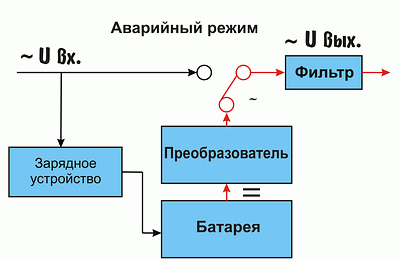
Line Interactive UPS are made according to the scheme with a switching device, supplemented by an input voltage stabilizer based on an autotransformer with switched windings. The main advantage of such devices is load protection against overvoltage or undervoltage without going into emergency mode. The disadvantage of such devices is also a non-zero (about 4 ms) switching time to batteries.


Double conversion UPS voltage differs in that in it the AC voltage entering the input is first converted by a rectifier into a DC, and then - with the help of an inverter - again into an AC. The battery is permanently connected to the output of the rectifier and the input of the inverter and supplies it in emergency mode. Thus, a sufficiently high stability of the output voltage is achieved regardless of voltage fluctuations at the input. In addition, interference and disturbances that are abundant in the supply network are effectively suppressed.
In practice, this UPS class behaves like a linear load when connected to AC power. The advantage of this design is zero switching time to battery power, the disadvantage is the decrease in efficiency due to losses during double voltage conversion.


Physics
All reference books on electrical engineering distinguish four types of power: instant, active, reactive and complete. Instant power is calculated as the product of the instantaneous voltage value and the instantaneous current value for an arbitrarily chosen moment in time, that is
![]()
Since in a circuit with resistance r u \u003d ir, then

The period average power P of the circuit under consideration is equal to the constant component of the instantaneous power

The average AC power over the period is called active ... The unit of active power, volt-ampere, is called watt (W).
Accordingly, the resistance r is called active. Since U \u003d Ir, then

Usually, it is the active power that is understood as the power consumption of the device.
Reactive power - a value characterizing the loads created in electrical devices by fluctuations in the energy of the electromagnetic field. For a sinusoidal current, it is equal to the product of the effective current and voltage by the sine of the phase angle between them.
![]()
Full power - the total power consumed by the load (both active and reactive components are taken into account). Calculated as the product of the rms input current and voltage. The unit of measurement is VA (Volt-Ampere). For sinusoidal current is

Almost any electrical device has a label indicating either the total power of the device or the active power.
Testing
The main purpose of testing - demonstrate the behavior of the tested UPS in real conditions, give an idea of \u200b\u200badditional characteristics that are not reflected in the general documentation for the device, in practice, determine the influence of various factors on the operation of the UPS and, possibly, help determine the choice of one or another uninterruptible power supply.
Despite the fact that there are currently a great many recommendations for choosing a UPS, during testing we expect, firstly, to consider a number of additional parameters that should be inquired before purchasing equipment, and secondly, if necessary, adjust the set of selected methods and parameters testing and develop a basis for future analysis of the entire power path of systems.
The general plan for testing is as follows:
- Specifying the device class
- Indication of the manufacturer's declared characteristics
- Description of the scope of delivery (availability of a manual, additional cords, software)
- Short description appearance UPS (functions located on the control panel and list of connectors)
- Battery type (indicating the capacity of the batteries, serviced / non-serviced, name, possibly - interchangeability, the ability to connect additional battery blocks)
- "Energy" component of the tests
During testing, it is planned to check the following parameters:
- The input voltage range at which the UPS operates on utility power without transferring to batteries. Larger input voltage range reduces UPS transfers to battery and extends battery life
- Time to switch to battery power. The shorter the transfer time, the lower the risk of failure of the load (device connected via the UPS). The duration and nature of the switching process largely determine the possibility of the normal continuation of the equipment operation. For a computer load, the permissible power interruption time is 20-40 ms.
- Oscillogram of switching to battery
- Switching time from battery to external power supply
- Oscillogram of switching from battery to external power supply
- Battery life. This parameter is solely determined by the capacity of the batteries installed in the UPS, which in turn increases as the maximum output power of the UPS increases. To provide autonomous power supply for two modern SOHO computers of a typical configuration for 15-20 minutes, the maximum output power of the UPS should be about 600-700 VA.
- Output voltage parameters for battery operation
- Pulse shape at the beginning of battery discharge
- Pulse shape at the end of battery discharge
- UPS output voltage range when input voltage changes. The narrower this range, the less the effect of changes in the input voltage on the supplied load.
- Output voltage stabilization
- Output voltage filtering (if any)
- UPS behavior during output overload
- UPS behavior in the event of a load failure
- Calculation of UPS efficiency. Defined as the ratio of the device's output power to the power consumption from the power source
- Total Harmonic Distortion, which characterizes the degree to which a voltage or current waveform differs from a sinusoidal one
- 0% - sinusoid
- 3% - distortion is not noticeable to the eye
- 5% - distortion is visible to the eye
- up to 21% - trapezoidal or stepped waveform
- 43% - the signal is rectangular
During testing, we will use not real workstations and servers, but equivalent loads, which have a stable consumption pattern and a power utilization factor close to 1. The following set is currently being considered as the main equipment that will be used during testing:
 Bibliography
- GOST 721-77 Power supply systems, networks, sources, converters and receivers of electrical energy. Rated voltages over 1000 V
- GOST 19431-84 Energy and Electrification. Terms and Definitions
- GOST 21128-83 Power supply systems, networks, sources, converters and receivers of electrical energy. Rated voltages up to 1000 V
- GOST 30372-95 Electromagnetic compatibility of technical equipment. Terms and Definitions
- Theoretical Electrical Engineering, ed. 9th, revised, M.-L., Energiya publishing house, 1965
- Company promotional materials
- Internet resource
Requirements for the quality of electricity are legally prescribed by state standards and rather strict regulations. Electricity supplying organizations make a lot of efforts to comply with them, but they are not always implemented.
In our apartments, and in production, periodically there are:
complete power outages for an indefinite period;
aperiodic short-time (10 ÷ 100 ms) high-voltage (up to 6 kV) voltage pulses;
surges and voltage drops with different duration;
high-frequency noise pads;
frequency drifts.
All these malfunctions negatively affect the work of residential and office electricity consumers. Particularly affected by the quality of power supply are microprocessor and computer devices, which not only fail, but can also completely lose their performance.
Purpose and types of uninterruptible power supplies
To reduce the risks of faults in the power supply network, redundant devices are used, which are commonly called uninterruptible power supplies (UPS) or UPS (derived from the abbreviation of the English phrase "Uninterruptible Power Supply").
They are manufactured in different designs to meet specific customer needs. For example, powerful UPSs with helium batteries are able to keep an entire cottage on power for several hours.

Their batteries receive charge from a power line, wind generator, or other carriers of electricity through an inverter rectifier device. They also feed the electrical consumers of the cottage.
When the external source is disconnected, the batteries are discharged to the load connected to their network. The larger the battery capacity and the lower their discharge current, the longer they work.
Medium power uninterruptible power supplies can back up indoor climate control systems and similar equipment.
At the same time, the simplest UPS models can only complete the computer emergency shutdown program. Moreover, the duration of the entire process of their work will not exceed 9-15 minutes.
Computer uninterruptible power supplies are:
built into the device case;
external.
The first designs are common in laptops, netbooks, tablets and similar mobile devices powered by a built-in battery, which is equipped with a power and load switching circuit.
Laptop battery with built-in controller is an uninterruptible power supply. Its circuit automatically protects operating equipment from power failures.

UPS external structures, intended for the normal completion of programs of a stationary computer, are manufactured in a separate unit.

They are connected via network adapter plug into an electrical outlet. Only those devices that are responsible for the operation of programs are powered from them:
system unit with a connected keyboard;
monitor displaying ongoing processes.
Rest peripherals: Scanners, printers, speakers and other equipment are not powered by UPS. Otherwise, in the event of an emergency termination of programs, they will take on part of the energy stored in the batteries.
Options for building UPS operating circuits
Computer and industrial UPS are manufactured in three main options:
power supply redundancy;
interactive scheme;
double conversion of electricity.
In the first method backup scheme, denoted by the English terms "Standby" or "Off-Line", the voltage is supplied from the network to the computer through the UPS, in which electromagnetic interference is eliminated by built-in filters. It is also installed here, the capacity of which is maintained by the charge current regulated by the controller.

When the external power supply disappears or goes beyond the established standards, the controller directs the battery energy to power the consumers. A simple inverter is connected to convert DC to AC.

UPS Standby Benefits
Uninterruptible power supplies of the Off-Line circuit have high efficiency, when the voltage is applied to them, they operate quietly, generate little heat and are relatively cheap.
disadvantages
UPS Standby stand out:
long transition to battery power 4 ÷ 13 ms;
a distorted form of the output signal produced by the inverter in the form of a square wave, and not a harmonic sinusoid;
lack of voltage and frequency adjustment.
Such devices are most common on personal computers.
UPS interactive circuit
They are designated by the English term "Line-Interactive". They are performed according to the previous, but more complicated scheme by turning on a voltage stabilizer using a step-controlled autotransformer.

This provides a correction for the value of the output voltage, but they are not able to control the signal frequency.


Noise filtering in normal mode and the transition to inverter power in case of emergencies occurs according to the UPS Standby algorithms.

The addition of a voltage stabilizer of various models with control methods made it possible to create inverters with a waveform of not only a square wave, but also a sinusoid. However, a small number of control stages based on relay switching does not allow full stabilization functions.
This is especially true for cheap models, which, when switching to battery power, not only overestimate the frequency above the nominal, but also distort the shape of the sinusoid. Interference is introduced by the built-in transformer, in the core of which hysteresis processes occur.
In expensive models, inverters operate on semiconductor switches. UPS Line-Interactive have a faster transition to battery power than Off-Line UPS. It is provided by the operation of the synchronization algorithms between the input voltage and the output signals. But at the same time, there is some underestimation of the efficiency.
Line-Interactive UPS cannot be used to power induction motors that are massively installed throughout household appliances, including heating systems. They are used to operate devices with where the power is filtered and rectified at the same time: computers and consumer electronics.
Double conversion UPS
This UPS scheme is named after the English phrase "On-line" and operates on equipment that requires high quality power supply. It performs a double conversion of electricity, when the sinusoidal harmonics of the alternating current are constantly converted by the rectifier to a constant value, which is passed through the inverter to create a repeated sinusoid at the output.
Here the battery is constantly connected to the circuit, which eliminates the need for its commutation. This method practically eliminates the period of preparation of the uninterruptible power supply for switching.
The operation of the UPS On-line according to the battery condition can be divided into three stages:
charging stage;
waiting state;
discharge on the computer.
Charge period
The sine wave input and output circuits are interrupted by an internal UPS switch.

The battery connected to the rectifier receives charge energy until its capacity is restored to optimal values.
Ready period
After the end of the battery charging, the automatic power supply unit closes the internal switch.
The battery maintains a standby state.
Discharge period
The battery is automatically transferred to the power supply of the computer station.
Uninterruptible power supplies operating on the double conversion method have a lower efficiency when powered from the line than other models due to the energy consumption for generating heat and noise. But in complex structures, techniques are used to increase efficiency.
UPS On-line is able to correct not only the voltage value, but also its oscillation frequency. This distinguishes them favorably from previous models and allows them to be used to power various complex devices with asynchronous motors. However, the cost of such devices is much higher than previous models.
UPS composition
Depending on the type of working scheme, the uninterruptible power supply kit includes:
accumulators for accumulating electricity;
Ensuring maintenance of the battery performance;
inverter for sine wave formation,
process control scheme;
software.
For remote access a local network can be used to the device, and the reliability of the circuit can be increased due to its redundancy.
In separate uninterruptible power supplies, the "Bypass" mode is used, when the load is powered by the filtered mains voltage without the operation of the main circuit of the device.
Part of the UPS has a “Booster” step voltage regulator, controlled by automatic equipment.
Depending on the need to carry out complex technical solutions, uninterruptible power supplies can be equipped with additional special functions.