Connecting a consumer to a household or industrial electric network, whose power is greater than that for which a cable or wire is designed, is fraught with the most unpleasant, and sometimes catastrophic, consequences. With the correct organization of the electrical wiring inside the living room, circuit breakers will constantly operate or fuses (plugs) will blow.
If the protection is not performed correctly or is absent altogether, this may result in:
- burnout of the supply wire or cable;
- melting of insulation and short circuit between wires;
- overheating of copper or aluminum cable cores of the wire and fire.
Therefore, before connecting the consumer to the mains, it is desirable to know not only its nameplate electric power, but also the current consumed from the network.
Power consumption calculation
The formula for calculating power in current and voltage is familiar from the school physics course. Calculation of electric current power (in watts) for a single-phase network is carried out according to the expression:
- in which U is the voltage in volts
- I is the current in amperes;
- Cosφ - power factor, depending on the nature of the load.

A question may arise - why do we need a formula for calculating current power when it can be found from the passport of the connected device? Determination of electrical parameters, including power and current consumption is necessary at the design stage of wiring. The maximum current flowing in the network determines the cross section of the wire or cable. To calculate the current by power, you can use the converted formula:
The power factor depends on the type of load (active or reactive). In household calculations, it is recommended to take its value equal to 0.90 ... 0.95. However, when connecting electric stoves, heaters, incandescent lamps, the load of which is considered active, this coefficient can be considered equal to 1.
The above formulas for calculating current and voltage power can be used for a single-phase network with a voltage of 220.0 volts. For a three-phase network, they have a slightly modified look.
Calculation of the power of three-phase consumers
The definition of power consumption for a three-phase network has its own specifics. The formula for calculating the electric current power of three-phase household consumers is:
P \u003d 3.00.5 × U × I × Cosφ or 1.73 × U × I × Cosφ,
Features of the calculation
The above formulas are intended for simplified household calculations. When determining the effective parameters, the real connection must be taken into account. A typical example is the calculation of power consumption from a battery. Since the current in the circuit flows constant, the power factor is not taken into account, since the nature of the load does not affect the power consumption. And for active and reactive consumers, its value is taken equal to 1.0.
The second nuance that should be taken into account when conducting household electrical calculations is the real value of the voltage. It is no secret that in rural areas the network voltage can fluctuate over a wide range. Therefore, using the calculation formulas in them, it is necessary to substitute the real values \u200b\u200bof the parameters.
Even more difficult is the task of calculating three-phase consumers. When determining the flowing current in the network, it is necessary to additionally take into account the type of connection - “star” or “triangle”.
When designing any electrical circuits, a power calculation is performed. Based on it, the selection of the main elements is made and the allowable load is calculated. If the calculation for the DC circuit is not difficult (in accordance with Ohm's law, it is necessary to multiply the current strength by the voltage - P \u003d U * I), then with the calculation of the AC power it is not so simple. For an explanation, you will need to turn to the basics of electrical engineering, without going into details, here is a brief summary of the main points.
Full power and its components
In AC circuits, power is calculated taking into account the laws of sinusoidal changes in voltage and current. In this regard, the concept of full power (S) was introduced, which includes two components: reactive (Q) and active (P). A graphical description of these quantities can be made through the power triangle (see Fig. 1).
The active component (P) means the power of the payload (the irreversible conversion of electricity into heat, light, etc.). This value is measured in watts (W), at the household level it is customary to calculate in kilowatts (kW), in the manufacturing sector - megawatts (mW).
The reactive component (Q) describes the capacitive and inductive electric load in the AC circuit, the unit of measurement of this value is Var.
Fig. 1. The triangle of powers (A) and voltages (B)In accordance with the graphical representation, the relations in the power triangle can be described using elementary trigonometric identities, which makes it possible to use the following formulas:
- S \u003d √P 2 + Q 2, - for full power;
- and Q \u003d U * I * cos\u2061 φ, and P \u003d U * I * sin φ - for the reactive and active components.
These calculations are applicable for a single-phase network (for example, domestic 220 V), for calculating the power of a three-phase network (380 V), it is necessary to add a factor of √3 (with a symmetrical load) or sum the powers of all phases (if the load is asymmetric) in the formulas.
For a better understanding of the process of exposure to the components of full power, let us consider the “pure” manifestation of the load in an active, inductive and capacitive form.
Active load
Let us take a hypothetical circuit in which a “pure” active resistance and an appropriate source of alternating voltage are used. A graphical description of the operation of such a circuit is shown in Figure 2, which displays the main parameters for a specific time range (t).
 Figure 2. Power of ideal active load
 We can see that voltage and current are synchronized both in phase and frequency, while power has a double frequency. Please note that the direction of this quantity is positive, and it is constantly increasing.
Capacitive load
As can be seen in Figure 3, the graph of capacitive load characteristics is slightly different from the active one.
 Figure 3. Graph of ideal capacitive load
 The oscillation frequency of the capacitive power is twice the frequency of the sinusoid voltage. As for the total value of this parameter, during one period of harmonic it is equal to zero. Moreover, an increase in energy (∆W) is also not observed. This result indicates that its movement occurs in both directions of the chain. That is, when the voltage increases, the charge accumulates in the capacitance. When a negative half-cycle occurs, the accumulated charge is discharged into the circuit.
In the process of energy storage in the load capacitance and subsequent discharge, useful work is not performed.
Inductive load
The graph below shows the nature of the “pure” inductive load. As you can see, only the direction of power has changed, as for the build-up, it is zero.

Negative reactive load
In the above examples, options where a “pure” reactive load was present were considered. The impact factor of the active resistance was not taken into account. Under such conditions, the reactive effect is zero, which means that you can not take it into account. As you know, in real conditions this is impossible. Even if such a load would hypothetically exist, the resistance of the copper or aluminum conductors of the cable necessary for its connection to the power source cannot be ruled out.
The reactive component can manifest itself in the form of heating of the active components of the circuit, for example, a motor, transformer, connecting wires, power cable, etc. A certain amount of energy is spent on this, which leads to a decrease in the main characteristics.
Reactive power acts on the circuit as follows:
- does not produce any useful work;
- causes serious losses and abnormal loads on electrical appliances;
- may cause a serious accident.
That is why, making the appropriate calculations for the electrical circuit, one cannot exclude the influence factor of inductive and capacitive loads and, if necessary, provide for the use of technical systems to compensate for it.
Power consumption calculation
In everyday life, one often has to deal with the calculation of power consumption, for example, to check the permissible load on the wiring before connecting a resource-intensive electric consumer (air conditioner, boiler, electric stove, etc.). Also, there is a need for such a calculation when choosing circuit breakers for a switchboard, through which the apartment is connected to electricity.
In such cases, the calculation of power by current and voltage is not necessary, it is enough to sum the consumed energy of all devices that can be turned on simultaneously. Without contacting the calculations, you can find out this value for each device in three ways:


In the calculations, it should be borne in mind that the starting power of some electrical appliances can differ significantly from the nominal. For household devices, this parameter is almost never indicated in the technical documentation, so you need to refer to the corresponding table, which contains the average values \u200b\u200bof the starting power parameters for various devices (it is advisable to choose the maximum value).
With the help of this video tutorial, you can independently study the topic "Electric current power". Using this video material, you can get an idea of \u200b\u200ba new concept - electric current power. The teacher will tell you what power is - work per unit of time - and how to use and calculate this value correctly.
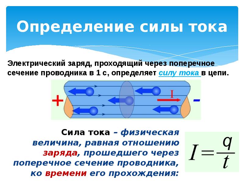
Definition
Power is the work done per unit of time.
In the documents for each electrical appliance, as a rule, two values \u200b\u200bare indicated: voltage (usually 220 V) and the power of this appliance.
To determine the electric power, it is necessary to divide the work of the electric current by the time the current flows along the electric circuit.
P - electrical power (in mechanics N - mechanical power)
What about work
Work is measured in Joules (J);
Time - in seconds (s);
Power (electrical and mechanical) is measured in Watts (W).
The device for measuring power is a wattmeter (Fig. 1).

Fig. 1. Wattmeter
Work is defined as the product of the current strength by the voltage and the time the current flows through the circuit.
In the formula for calculating the work, we substitute in the formula for calculating the power, the time t will be reduced. This means that the power does not depend on the time the electric current flows in the circuit, but is defined as the product of the voltage and the current strength.
From Ohm's law for a chain section
![]()
The power of electric current is a value that characterizes the performance of a given device. In everyday life, all devices are designed for the same voltage - 220 V. From the first equation it follows that if the power increases, the voltage is constant, then the current strength will also increase.
For example, while heating water in an electric kettle, the wire connecting the kettle to the electric circuit is heated. This means that the kettle’s power is quite large, the voltage is 220 V, and the current that flows in the circuit of the included electric kettle is also quite large.
Paying for electric energy, we pay for the work of electric current. This payment is made in kilowatt hours.
1 kW \u003d 1000 W;
1 hour \u003d 3600 s;
(work is defined as power times time);
1 kWh \u003d 3 600 000 J.
Got a unit for calculating the work of electric current - 1 kW ∙ h \u003d 3 600 000 J.
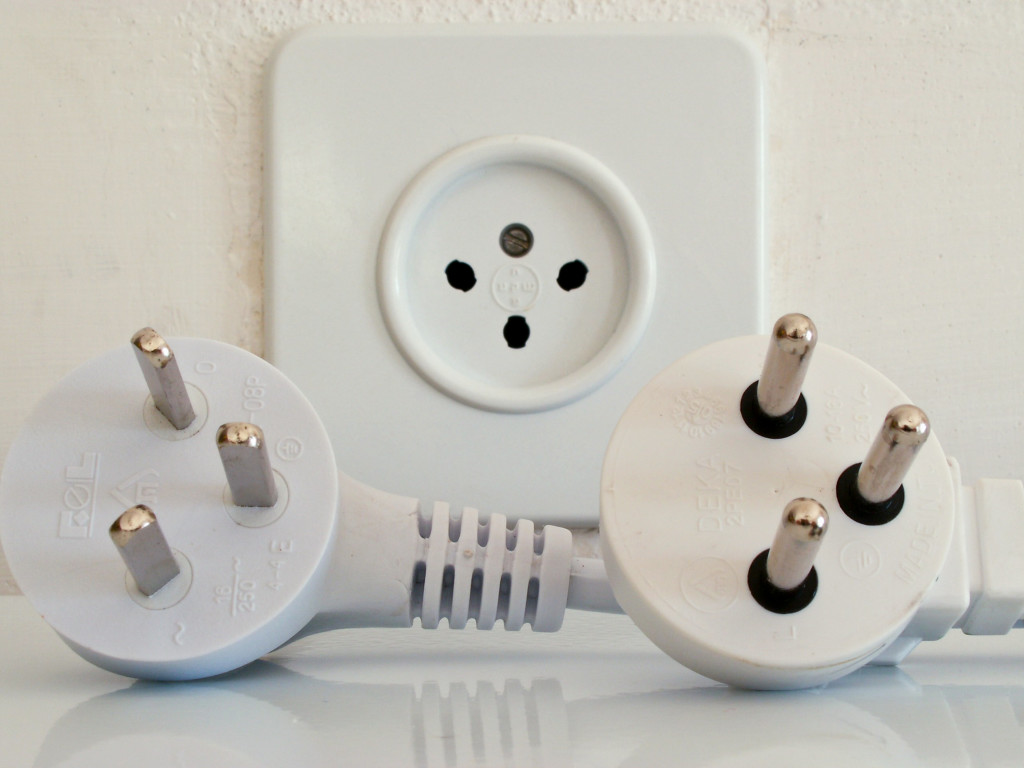
Based on the foregoing, we can conclude that it is impossible to turn on several devices at once in the same outlet. Voltage is a constant value (220 V), and the current strength in the circuit changes. The more devices are turned on, the greater the electric current in the circuit.
Bibliography
- Gendenshtein L.E., Kaydalov A.B., Kozhevnikov V.B. / Ed. Orlova V.A., Royzen I.I. Physics 8. - M.: Mnemosyne.
- Peryshkin A.V. Physics 8. - M.: Bustard, 2010.
- Fadeeva A.A., Zasov A.V., Kiselev D.F. Physics 8. - M.: Education.
- Electrono.ru ().
- Electricalschool.info ().
- Stoom.ru ().
Homework
- P. 51, 52, questions 1-6, p. 121, 1-3, p. 122, task 25 (2). Peryshkin A.V. Physics 8. - M.: Bustard, 2010.
- Find the current power in an electric lamp if the current in it is 0.4 A and the voltage in the circuit is 220 V.
- What instruments can measure the power of an electric field?
Electric current power is the speed of the work performed by the circuit. Simple definition, trouble with understanding. Power is divided into active, reactive. And it begins ...
Work electric current, power
When the charge moves along the conductor, the field performs work on it. The value is characterized by tension, in contrast to tension in free space. The charges move in the direction of decreasing potentials, an energy source is required to maintain the process. The voltage is numerically equal to the work of the field when moving on a unit charge (1 C). In the course of interactions, electrical energy passes into other forms. Therefore, it is necessary to enter a universal unit, a physical freely convertible currency. In the body, ATP acts as a measure, electricity - the work of the field.
Electric arc
In the diagram, the moment of energy conversion is displayed in the form of EMF sources. If the generators are directed in one direction, the consumer - necessarily in the other. A clear fact is reflected in the process of power consumption, selection from energy sources. EMF carries the opposite sign, often called counter-EMF. Avoid confusing the concept with the phenomenon that occurs in inductors when turning off the power. Counter-EMF means the transition of electrical energy into chemical, mechanical, and light.
The consumer wants to complete the work in a certain unit of time. Obviously, the lawn mower does not intend to wait for winter, hopes to manage by dinner. The power of the source should provide a given execution speed. The work is carried out by electric current, therefore, the concept also applies. Power is active, reactive, usable and power loss. Areas denoted by physical circuits by resistances are harmful in practice and are costs. Heat is generated on the resistors of the conductors, the Joule-Lenz effect leads to excess power consumption. An exception is heaters where a phenomenon is desired.
Useful work on physical circuits is denoted by counter-EMF (ordinary source with a direction opposite to the generator). For power, there are several analytic expressions. Sometimes it is convenient to use one, in other cases - another (see. Fig.):

Expressions of current power
- Power is the speed of work.
- Power is equal to the product of voltage and current.
- The power spent on thermal action is equal to the product of resistance per square current.
- The power spent on thermal action is equal to the ratio of the square of the voltage to the resistance.
It is easier to use the second formula for current clamp mites. Regardless of the nature of the load, we calculate the power. Only active. Power is determined by many factors, including temperature. By the nominal value for the device we mean the one developed in the steady state. For heaters, the third, fourth formula should be used. Power depends entirely on the parameters of the supply network. Designed to work with 110 volts of alternating current in European conditions, they will quickly burn out.
Three phase circuit
For beginners, three-phase circuits are complex, in fact it is a more elegant technical solution. Even electricity is supplied by the house in three lines. Inside the entrance is divided into apartments. More confusing is the fact that some devices for three phases are devoid of grounding, a neutral wire. Isolated neutral circuits. A neutral wire is not needed, the current is returned to the source through phase lines. Of course, the load on each core is increased. PUE requirements separately specify the kind of network. For three-phase circuits, the following concepts are introduced, which you need to have an idea in order to correctly calculate the power:

Three-phase insulated neutral circuit
- The phase voltage, current is called, respectively, the potential difference and the speed of movement of the charge between phase and neutral. It is clear that in the case specified above with complete isolation, the formulas will be invalid. Since there is no neutral.
- Linear voltage, current is called, respectively, the potential difference or the speed of movement of the charge between any two phases. The numbers are clear from the context. When they talk about networks of 400 volts, they mean three wires, the potential difference with neutral is 230 volts. Line voltage is higher than phase voltage.
There is a phase shift between voltage and current. What school physics is silent about. The phases coincide if the load is 100% active (simple resistors). Otherwise, a shift appears. In the inductance, the current lags the voltage by 90 degrees, in the capacitance it is ahead. Simple truth is easily remembered as follows (we gradually approach reactive power). The imaginary part of the inductance resistance is jωL, where ω is the circular frequency equal to the usual (in Hz) multiplied by 2 Pi numbers; j is the operator indicating the direction of the vector. Now we write Ohm's law: U \u003d I R \u003d I jωL.
It can be seen from the equality: the voltage must be postponed upward by 90 degrees when building the diagram, the current will remain on the abscissa axis (horizontal axis X). Rotation according to the rules of radio engineering occurs counterclockwise. Now the fact is obvious: the current lags 90 degrees. By analogy, we carry out a comparison for a capacitor. The resistance to alternating current in imaginary form looks like this: -j / ωL, the sign indicates: it will be necessary to put off the voltage down, perpendicular to the abscissa axis. Consequently, the current is 90 degrees ahead of phase.
In reality, in parallel with the imaginary part, there is a real one - called active resistance. The coil wire is represented by a resistor, being a retinue, acquires inductive properties. Therefore, the real phase angle will not be 90 degrees, slightly less.
And now you can move on to the current power formulas of three-phase circuits. Here the line forms a phase shift. Between voltage and current, and relative to another line. You must admit that without the knowledge carefully presented by the authors, a fact cannot be realized. Between the lines of an industrial three-phase network, a shift of 120 degrees (full revolution - 360 degrees). Provides uniform rotation of the field in the engines, for ordinary consumers it is indifferent. So it is more convenient for hydroelectric power generators - the load is balanced. The shift is between the lines, in each current the voltage is ahead or lags:
- If the line is symmetrical, the current shifts between any phases are 120 degrees, the formula is extremely simple. But! If the load is symmetrical. Let's see the image: the phase f is not 120 degrees, it characterizes the shift between the voltage and current of each line. It is assumed that they turned on the engine with three equivalent windings, this is the result. If the load is asymmetrical, take the trouble to calculate for each line separately, then add the results together to get the total current power.
- The second group of formulas is given for three-phase circuits with isolated neutral. It is assumed that the current of one line flows through another. Neutral is absent as unnecessary. Therefore, the voltages are taken not phase (there is nothing to count from), as the previous formula, but linear. Accordingly, the numbers indicate which parameter should be taken. Stop being scared of Greek letters - the phase between two multiplied parameters. The numbers are reversed (1.2 or 2.1) to correctly take into account the sign.
- In an asymmetric circuit, phase voltage, current again appears. Here, the calculation is carried out separately for each line. There are no options.

In practice, measure current power
Hinted, you can use current clamps. The device will determine the cruising parameters of the drill. Acceleration can be detected only with repeated experiments, the process is extremely fast, the display change frequency is not higher than 3 times per second. Current clamps show an error. Practice shows: to achieve the error indicated in the passport is difficult.
Most often, for the assessment of power, meters are used (for payments to suppliers), wattmeters (for personal and work purposes). The dial gauge contains a pair of fixed coils, along which the circuit current flows, a movable frame, to establish voltage by parallel switching on the load. The design is designed to immediately realize the full power formula (see. Fig.). The current is multiplied by the voltage and a certain coefficient taking into account the graduation of the scale, also by the cosine of the phase shift between the parameters. As mentioned above, the shift fits within 90 - minus 90 degrees, therefore, the cosine is positive, the torque of the arrow is directed in one direction.
There is no way to tell whether the load is inductive or capacitive. But in case of improper inclusion in the circuit, the readings will be negative (blockage to the side). A similar event will occur if the consumer suddenly begins to give power back to the load (it happens). In modern devices, something similar happens, the calculation is carried out by an electronic module that integrates energy consumption, or reads power readings. Instead of an arrow, there is an electronic indicator and many other useful options.
Special problems are caused by measurements in asymmetric circuits with insulated neutral, where it is impossible to directly add the power of each line. Wattmeters are divided by the principle of action:
- Electrodynamic. Described by section. Consist of one movable, two fixed coils.
- Ferrodynamic. Reminds a motor with a split pole (shaded-pole motor).
- With a quad. The amplitude-frequency characteristic of a nonlinear element (for example, a diode), resembling a parabola, is used to square the electric quantity (used in calculations).
- With a Hall sensor. If the induction is made using a coil proportional to the magnetic field voltage in the sensor, a current is applied, the EMF will be the result of multiplying two values. The desired value.
- Comparators Gradually increases the reference signal until equality is achieved. Digital instruments achieve high accuracy.
In circuits with a strong phase shift, a sine wattmeter is used to estimate losses. The design is similar to that considered, the spatial position is such that the reactive power is calculated (see. Fig.). In this case, the product of current and voltage is multiplied by the sine of the phase angle. Reactive power is measured by a conventional (active) wattmeter. There are several techniques. For example, in a three-phase symmetrical circuit, it is necessary to include a series winding in one line, parallel in two others. Then, calculations are made: the readings of the device are multiplied by a root of three (taking into account that the product is a product of current, voltage and sine of the angle between them).

For a three-phase circuit with simple asymmetry, the task is complicated. The figure shows the technique of two power meters (ferrodynamic or electrodynamic). Starts of windings are indicated by asterisks. The current passes through the series, the voltage from two phases is supplied to the parallel (one through the resistor). The algebraic sum of the readings of both wattmeters is added up, multiplied by a root of three to obtain the reactive power value.
Electric current
A constant voltage is applied to the circuit shown in Figure 1. U.
U = φ A – φ B
During t electricity flowed through the circuit Q. The forces of the electric field acting along the conductor transferred a charge during this time Q from point BUTexactly B. The work of the electric forces of the field or, equivalently, the work of the electric current can be calculated by the formula:
A = Q × ( φ A – φ B) = Q × U,
Because Q = I × t, then finally:
A= U × I × t,
where A - work in joules; I - current in amperes; t - time in seconds; U - voltage in volts.
Ohm's law U = I × r. Therefore, the formula of work can be written as follows:
A = I 2 × r × t.
Electric current power
Work performed per unit of time is called power and is denoted by the letter P.
From this formula we have:
A = P × t.
Power unit:
![]()
![]()
1 (J / s) is otherwise called a watt (W). Substituting into the power formula the expression for the electric current, we have:
![]()
![]()
P = U × I (Tue).
The formula for electric current power can also be expressed in terms of current consumption and consumer resistance:
In addition to watts, in practice, larger units of electrical power are used. Electric power is measured in:
100 W \u003d 1 hectowatt (gW);
1000 W \u003d 1 kilowatt (kW);
1,000,000 W \u003d 1 megawatt (MW).
Electric power is measured by a special device - a wattmeter. A power meter has two windings (coils): serial and parallel. The serial coil is current and is connected in series with the load on the section of the circuit where measurements are made, and the parallel coil is a voltage coil, it is accordingly connected in parallel with this load. The principle of operation of a wattmeter is based on the interaction of two magnetic fluxes generated by a current flowing through the winding of a moving coil (current coil), and a current passing through a fixed coil (voltage coil). When the measured current passes through the windings of the movable and fixed coils, two magnetic fields are formed, during the interaction of which the movable coil tends to be located so that the direction of its magnetic field coincides with the direction of the magnetic field of the fixed coil. The moment created by the coil springs, through which the measured current is conducted into the movable coil, counteracts the rotating moment. The opposing moment of the springs is directly proportional to the angle of rotation of the coil. An arrow mounted on a moving coil indicates the value of the measured value. The power meter wiring diagram is shown in Figure 2.
If you decide to measure the power consumption, what kind of load you have, and at the same time you do not have a power meter, you can "make" a power meter yourself. From the formula P = I × U it can be seen that the power consumed in the network can be determined by multiplying the current by voltage. Therefore, to determine the power consumed from the network, two devices should be used, a voltmeter and an ammeter. Having measured the current consumption with a voltmeter and the voltage of the mains with a voltmeter, it is necessary to multiply the ammeter reading by the voltmeter reading.
So, for example, the power consumed by the resistance r, with a reading of an ammeter of 3 A and a voltmeter of 220 V, it will be:
P = I × U \u003d 3 × 220 \u003d 660 watts.
For practical measurements of electrical work (energy), the joule is too small a unit.
If time t substitute not in seconds but in hours, then we will get larger units of electric energy:
1 J \u003d 1 W × sec;
1 W × h \u003d 3600 watts × seconds \u003d 3600 J;
100 W × h \u003d 1 hectowatt × hour (gW × h);
1000 W × h \u003d 1 kilowatt × hour (kW × h).
Electric energy is measured by electric energy meters.
Video 1. Work and power of electric current
Video 2. A little more about power
Example 1 Determine the power consumed by an electric motor if the current in the circuit is 8 A and the motor is connected to a 220 V network.
P = I × U \u003d 8 × 220 \u003d 1760 W \u003d 17.6 gW \u003d 1.76 kW.
Example 2 What is the power consumed by the electric tile if the tile takes a current of 5 A from the network and the resistance of the tile spiral is 24 Ohms?
P = I 2 × r \u003d 25 × 24 \u003d 600 W \u003d 6 gW \u003d 0.6 kW.
When converting mechanical power into electrical power and vice versa, it must be remembered that
1 horsepower (hp) \u003d 736 watts;
1 kilowatt (kW) \u003d 1.36 liters. with.
Example 3 Determine the energy consumed by a 600 W electric stove for 5 hours.
A = P × t \u003d 600 × 5 \u003d 3000 W × h \u003d 30 gW × h \u003d 3 kW × h
Example 4 Determine the cost of burning twelve electric lamps per month (30 days), if four of them 60 W each burn 6 hours a day, and the remaining eight lamps 25 W each burn 4 hours a day. The price for energy (tariff) is 2.5 rubles per 1 kW × h.
The power of four lamps of 60 watts.
P \u003d 60 × 4 \u003d 240 watts.
t \u003d 6 × 30 \u003d 180 hours.
A = P × t \u003d 240 × 180 \u003d 43,200 W × h \u003d 43.2 kW × h.
The power of the remaining eight lamps is 25 watts.
P \u003d 25 × 8 \u003d 200 watts.
The number of hours of burning these lamps per month:
t \u003d 4 × 30 \u003d 120 hours.
The energy spent by these lamps:
A = P × t \u003d 200 × 120 \u003d 24000 W × h \u003d 24 kW × h.
Total energy spent:
43.2 + 24 \u003d 67.2 kW × h
Cost of all energy consumed:
67.2 × 2.5 \u003d 168 rubles.