Their average capacity is 12 mAh. In order for the device to always remain in working condition, you need a charger. However, in terms of voltage, they are quite different.
Nowadays, models for 12, 14 and 18 V are produced. It is also important to note that manufacturers use various components for chargers. In order to understand this issue, you should look at the standard charger circuit.
Charging scheme
The standard electrical circuit of the screwdriver charger includes a three-channel type microcircuit. In this case, four transistors are required for a 12 V model. In terms of capacity, they can vary quite a lot. In order for the device to cope with a high clock frequency, capacitors are attached to the microcircuit. They are used for charging both pulsed and transitional types. In this case, it is important to take into account the characteristics of specific batteries.
Thyristors are directly used in devices for current stabilization. Some models have open type tetrodes. According to the current conductivity, they differ from each other. If we consider modifications to 18 V, then there are often dipole filters. These elements make it easy to deal with network congestion.

Modifications for 12V
A 12 V screwdriver (the circuit is shown below) is a set of transistors with a capacity of up to 4.4 pF. In this case, the conductivity in the circuit is provided at the level of 9 microns. Capacitors are used to ensure that the clock frequency does not increase sharply. Resistors in models are used mainly field.
If we talk about charging on tetrodes, then there is an additional phase resistor. It copes well with electromagnetic vibrations. Negative resistance with 12 V charges is maintained at 30 ohms. They are most often used for 10 mAh batteries. To date, they are actively used in models of the Makita trademark.

14V chargers
The charger circuit for a 14 V transistor screwdriver includes five pieces. Directly, the microcircuit for converting current is only suitable for a four-channel type. Capacitors for 14 V models are pulsed. If we talk about batteries with a capacity of 12 mAh, then tetrodes are additionally installed there. In this case, there are two diodes on the microcircuit. If we talk about the charging parameters, then the current conductivity in the circuit, as a rule, fluctuates around 5 microns. On average, the capacitance of the resistor in the circuit does not exceed 6.3 pF.
Directly, 14 V charging current loads can withstand 3.3 A. Triggers in such models are installed quite rarely. However, if we consider Bosch screwdrivers, then they are often used there. In turn, for Makita models, they are replaced by wave resistors. In order to stabilize the voltage, they fit well. However, the frequency of charging can vary greatly.
Model diagrams for 18 V
At 18 V, the screwdriver charger circuit assumes the use of only transition type transistors. There are three capacitors on the chip. The tetrode is directly installed with a grid trigger used in the device to stabilize the limiting frequency. If we talk about charging parameters at 18 V, then it should be mentioned that the current conductivity fluctuates around 5.4 microns.
If we consider charging for Bosch screwdrivers, then this figure may be higher. In some cases, chromatic resistors are used to improve signal conductivity. In this case, the capacitance of the capacitors should not exceed 15 pF. If we consider chargers of the Interskol trademark, then they use transceivers with increased conductivity. In this case, the maximum current load parameter can reach up to 6 A. In the end, mention should be made of Makita devices. Many of the battery models are equipped with high-quality dipole transistors. With increased negative resistance, they cope well. However, problems in some cases arise with magnetic oscillations.
Chargers "Intreskol"
The standard charger of the Interskol screwdriver (the diagram is shown below) includes a two-channel microcircuit. Capacitors are selected for her all with a capacity of 3 pF. In this case, transistors for 14 V models are used as pulse type. If we consider modifications to 18 V, then there you can find variable analogues. The conductivity of these devices can reach up to 6 microns. In this case, the batteries are used on average at 12 mAh.

Scheme for the model "Makita"
The charger circuit has a three-channel type chip. There are three transistors in the circuit. If we talk about 18 V screwdrivers, then in this case, capacitors are installed with a capacity of 4.5 pF. Conductivity is provided in the region of 6 microns.
All this allows you to remove the load from the transistors. Directly tetrodes are used open type. If we talk about modifications to 14 V, then the charges are available with special triggers. These elements allow you to perfectly cope with the increased frequency of the device. At the same time, they are not afraid of jumps in the network.

Bosch screwdriver chargers
The standard Bosch screwdriver includes a three-channel type chip. In this case, the transistors are of the pulse type. However, if we talk about 12 V screwdrivers, then transitional analogues are installed there. On average, they have a bandwidth of 4 microns. Capacitors in devices are used with good conductivity. There are two diodes in the chargers of the presented brand.
Triggers in devices are used only at 12 V. If we talk about the protection system, then transceivers are used only in an open type. On average, they are able to carry a current load of 6 A. In this case, the negative resistance in the circuit does not exceed 33 Ohms. If we talk separately about 14 V modifications, then they are produced for 15 mAh batteries. Triggers are not used. There are three capacitors in the circuit.

Scheme for the model "Skill"
The charger circuit includes a three-channel microcircuit. In this case, the models on the market are presented at 12 and 14 V. If we consider the first option, then the transistors in the circuit are used of a pulsed type. Their current reducibility is no more than 5 microns. In this case, triggers are used in all configurations. In turn, thyristors are used only for charging at 14 V.
Capacitors for 12 V models are installed with a varicap. In this case, they are not able to withstand large overloads. In this case, the transistors overheat quite quickly. There are three diodes directly in charging at 12 V.
Application of LM7805 Regulator
The charger circuit for a screwdriver with an LM7805 regulator includes only two-channel microcircuits. Capacitors are used on it with a capacity of 3 to 10 pF. You can most often meet regulators of this type with models of the Bosch brand. Directly for charging at 12 V, they are not suitable. In this case, the negative resistance parameter in the circuit reaches 30 ohms.
If we talk about transistors, then they are used in models of a pulse type. Triggers for regulators can be used. There are three diodes in the circuit. If we talk about modifications to 14 V, then tetrodes are only suitable for them of the wave type.
Using transistors BC847
The BC847 transistorized screwdriver charger circuit is quite simple. These elements are used most often by Makita. They are suitable for 12 mAh batteries. In this case, microcircuits are used three-channel type. Capacitors are used with dual diodes.
The triggers themselves are open-type, and their current conductivity is at the level of 5.5 microns. In total, three transistors are required for charging at 12 V. One of them is installed at the capacitors. The rest in this case are behind the reference diodes. If we talk about voltage, then charging at 12 V overloads with these transistors is capable of transferring 5 A.

IRLML2230 transistorized device
Charging circuits with transistors of this type are quite common. The company "Intreskol" uses them in versions for 14 and 18 V. In this case, microcircuits are used only three-channel type. Directly, the capacitance of these transistors is 2 pF.
They tolerate current overloads from the network well. In this case, the conductivity indicator in charging does not exceed 4 A. If we talk about other components, then capacitors are installed of a pulse type. In this case, you need three. If we talk about 14 V models, then they have thyristors for voltage stabilization.
Often, drill buyers complain that the “native” charger for a screwdriver charges the battery too slowly. As a result, you have to repeatedly postpone work for 2-4 hours. There are 2 options to avoid this situation. In the first case, you will need to purchase a new charger, in the second - do it yourself.
Types of batteries
To figure out how to make a charger for a screwdriver, you first need to study the types of batteries and their charge modes. There are 3 types of batteries:
Nickel-cadmium
This type is referred to as Ni-Cd, it is considered a good voltage source that is capable of delivering high power. The only drawback is that such batteries are on the list of prohibited products for environmental reasons, so this variety will now be much less common on sale.

Nickel-cadmium batteries have an energy capacity of 1200 to 1500 mAh. The total power is provided and maintained by the number of cans inside
The maximum cell voltage is 1.2 V. The battery is charged with an electric current of 0.1-1 rated capacity. It turns out that a battery with a capacity of 5 A * h is allowed to be recharged with a current of 0.5-5 A.
VIDEO: 5 rules for charging nickel-cadmium batteries
Another name is Pb with acid gel filling. They have average performance and low cost. Minus - the batteries have a large mass, due to which they make the device heavier. The main advantage is that it can be used in any position without electrolyte leaking out of the container.

Their main feature is high voltage and resistance, so that even by the end of the charge-discharge cycle, there is no sharp drop in voltage.
The maximum cell voltage level is 2 V, while the battery charging current always corresponds to 0.1 C.
Li-ion batteries for screwdriver
The most common type due to the complete tightness of the container. This option is characterized by increased power density, safety, environmental friendliness, low weight and ease of disposal.

Li-ion battery for screwdriver Li-ion 18650 Samsung 12.6V (Volt) 2400mAh
The lithium-ion cell has a maximum power of 3.3 volts. The voltage can be smoothly increased at room temperature from 0.1 to 1 C. This speeds up the charging process. But this method is only suitable for those batteries that have not been recharged.
It is important to remember here that the screwdriver is charged up to 4.2 Volts, its excess will affect the reduction of the service life, the decrease will reduce the capacity. It is very important to monitor the temperature when recharging.
When developing a do-it-yourself charger circuit for a screwdriver, it is very important to consider which battery you plan to charge. And also you need to additionally calculate its voltage - 12 Volts or 18 Volts. When using a charger for a screwdriver, it is necessary to monitor the process using a multimeter or a system with a voltage comparator that has been pre-configured for a specific type of battery.
VIDEO: Rules for choosing a battery for a screwdriver
How to assemble your own charger
Creating a homemade charger for a screwdriver requires compliance with safety regulations and work strictly according to a given scheme. You can use the drawing below, which is universal, since such charging equipment will be suitable for any type of battery. Here, only the charge current is an important parameter.

Homemade charging
When recharging, the current value fully corresponds to the current state of the battery, and when the process is completed, the indicator becomes a little larger.

Scheme of the simplest memory for a screwdriver
The charger for the screwdriver acts as an electric current generator on the transistor VT2. It, in turn, receives power through a rectifier bridge in contact with a step-down transformer. The charge current level is adjusted by the resistor R1 regulator when the battery is on. It will always remain unchanged. R3 works as a rated current limiter. VD 6 - LED, it acts as an indicator that determines whether charging is ongoing or has already been completed.
All components from the charger circuit for a screwdriver are installed on a printed circuit board; domestic devices KD202 and d242 can be used as diodes. It is required to place the elements in such a way that there is a minimum number of intersections on the board, it will be ideal if there is none. Leave at least 3 mm between parts.
The transistor is mounted on a heat sink 25-55 cm 2 . The field for connecting charging components for screwdrivers must be covered with a case. There may be difficulties with the terminals and connecting the battery. Therefore, it is better to modify the screwdriver charger by upgrading the old one:
- open the case of an obsolete charger;
- remove from it all the constituent parts and other stuffing;
- install a homemade circuit in the case.
The diagram must contain the following elements:
|
Position name |
a brief description of |
|
1N-4001 Series Rectifier Diode |
|
|
Standard LED |
|
|
Multi-colored LED of various types |
|
|
Wire type variable resistor 10 |
|
|
Resistor element of the MLT0.25 series at 330 Ohm |
|
|
Resistor MLT2.1 Ohm |
|
|
K5035 or 220 1000mF over 50 Volts |
|
|
Transistor part KT 361V |
|
|
Power transformer for 220/24 V and a power indicator of 100 W |
Stages of work:
- Choose the most optimal dimensions for the circuit, which can easily fit into the case with all the listed components.
- Draw with a thread all its paths according to the principal drawing, etch in a copper frame and unsolder all the elements.
- Mount the heatsink on the aluminum plate so that it does not come into contact with any part of the board.
- Fix the transistor securely with the M-3 nut.
- Assemble the components strictly according to the diagram and solder the terminals to all the necessary parts, observing the polarity. Bring out the electrical wire for the transformer.
- Install the transformer itself, together with a 0.5 A fuse, into the case and equip it with an adapter to turn on recharging.
VIDEO: How to charge a Li-ion battery from a screwdriver
Screwdriver charger rating
For those who do not plan to engage in self-assembly, we offer to choose from a range of ready-made chargers from different manufacturers.
DEWALT DCB118
The FLEXVOLT DEWALT DCB118 universal attachment is used to restore DEWALT 54V screwdriver batteries, any other devices with a nominal voltage of 18 volts can be charged with equal success.

FLEXVOLT DEWALT DCB118
For convenience, there is an indicator on the body, so you can control the process. Type of rechargeable batteries Li-ion. Weight 850 gr. The price of equipment is 3500 rubles.
ONE+ Ryobi RC18120
Claimed to be a highly specialized accessory for charging Ryobi ONE+ series batteries only. The advantage of having only one power supply - due to this, even the weight of the device is reduced (only 460 gr.), At the same time, the IntelliCell™ intelligent monitoring system is introduced, when each cell is charged to the maximum within 40-50 minutes, while increasing battery life .

ONE+ Ryobi RC18120
The voltage is 18 volts, the battery type is nickel-cadmium and lithium-ion. There are 4 positions of the level indicator - 25…50…75…100%. The case itself can be mounted on the wall. There is a level indicator light. The cost of the device is 4850 rubles.
DC10WC (10.8V) Makita
The device is used to restore lithium-ion batteries with a nominal voltage of 10.8 volts. There is a light indication, but there is no automatic stop. It is desirable to control the time in order to prevent overfilling of the container.

DC10WC (10.8V) Makita
Weight 1200 gr. with relatively small dimensions - only 20 cm long. There is a 1-year manufacturer's warranty. Price 2200 rub.
VIDEO: How to properly charge Li-ion
Cordless tools are more mobile and easier to use than their corded counterparts. But we must not forget about the significant drawback of the cordless tool, as you yourself understand the fragility of the batteries. Buying new batteries separately is comparable in price to purchasing a new tool.
After four years of service, my first screwdriver, or rather the batteries, began to lose capacity. To begin with, I assembled one from two batteries by choosing working "banks", but this modernization did not last long. I converted my screwdriver to a network one - it turned out to be very inconvenient. I had to buy the same, but a new 12 volt Interskol DA-12ER. The batteries in the new screwdriver lasted even less. As a result, two serviceable screwdrivers and not one working battery.
There is a lot of writing on the Internet about how to solve this problem. It is proposed to convert used Ni-Cd batteries to Li-ion batteries of size 18650. At first glance, there is nothing complicated about this. You remove the old Ni-Cd batteries from the case and install new Li-ion ones. But it turned out not to be so simple. The following describes what to pay attention to when upgrading a cordless tool.

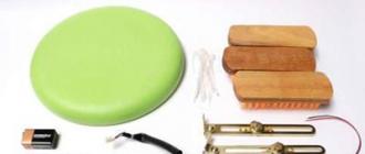
For conversion you will need:
I'll start with 18650 lithium-ion batteries. Purchased at.

The nominal voltage of the 18650 elements is 3.7 V. According to the seller, the capacity is 2600 mAh, marking ICR18650 26F, dimensions 18 by 65 mm.
The advantages of Li-ion batteries over Ni-Cd are smaller dimensions and weight, with a larger capacity, as well as the absence of the so-called "memory effect". But lithium-ion batteries have serious disadvantages, namely:
1. Negative temperatures drastically reduce capacity, which cannot be said about nickel-cadmium batteries. Hence the conclusion - if the tool is often used at low temperatures, then replacing with Li-ion will not solve the problem.
2. A discharge below 2.9 - 2.5V and overcharging above 4.2V can be critical, complete failure is possible. Therefore, a BMS board is needed to control charge and discharge, if it is not installed, then new batteries will quickly fail.
On the Internet, they mainly describe how to convert a 14 volt screwdriver - it is ideal for retrofitting. With a series connection of four 18650 cells and a nominal voltage of 3.7V. we get 14.8V. - just what you need, even when fully charged, plus another 2V, this is not scary for the electric motor. And what about the 12V tool. There are two options, install 3 or 4 18650 elements, if three then it seems to be not enough, especially with partial discharge, and if four - a bit too much. I chose four and in my opinion made the right choice.
And now about the BMS board, it is also from AliExpress.

This is the so-called charge control board, battery discharge, specifically in my case CF-4S30A-A. As can be seen from the marking, it is calculated for a battery of four "cans" of 18650 and a discharge current of up to 30A. It also has a so-called “balancer” built into it, which controls the charge of each element separately and eliminates uneven charging. For the correct operation of the board, the batteries for the assembly are taken from the same capacity and preferably from the same batch.
In general, there are a great many BMS boards with different characteristics on sale. I don’t advise you to take it for a current below 30A - the board will constantly go into protection and to restore work on some boards you need to briefly apply charging current, and for this you need to remove the battery and connect it to the charger. There is no such drawback on the board that we are considering, just release the trigger of the screwdriver and in the absence of short circuit currents, the board will turn on by itself.

To charge the converted battery, the native universal charger was perfect. In recent years, Interskol began to equip its tools with universal chargers.

The photo shows to what voltage the BMS board charges my battery together with a standard charger. The voltage on the battery after charging 14.95V is slightly higher than what is needed for a 12 volt screwdriver, but it is rather even better. My old screwdriver became faster and more powerful, and fears that it would burn out after four months of use gradually dissipated. That seems to be all the main nuances, you can start reworking.

We disassemble the old battery.

We solder the old cans and leave the terminals together with the temperature sensor. If you remove the sensor as well, then when using a standard charger, it will not turn on.

According to the diagram in the photo, we solder 18650 cells into one battery. Jumpers between the "banks" must be made with a thick wire of at least 2.5 kv. mm, since the currents during the operation of the screwdriver are large, and with a small section, the power of the tool will drop sharply. The network writes that it is impossible to solder Li-ion batteries because they are afraid of overheating, and they recommend connecting using spot welding. You can only solder a soldering iron with a power of at least 60 watts. The most important thing is to solder quickly so as not to overheat the element itself.

It should look like it fits into the battery case.
A screwdriver is an indispensable tool, but a flaw found makes us think about how to make some improvements and improve the circuitry of its charger. Leaving the screwdriver to charge overnight, the author of this video blogger AKA KASYAN the next morning I discovered the heating of the battery of unknown origin. Moreover, the heating was quite serious. This is not normal and will drastically shorten battery life. In addition, it is dangerous from the point of view of fire safety.
Having disassembled the charger, it became clear that inside is a simple circuit of a transformer and a rectifier. In the docking station, things were even worse. Indicator LED and a small circuit on a single transistor, which is only responsible for the operation of the indicator when the battery is inserted into the docking station.
No charge control nodes and auto-shutdown, only a power supply that will charge indefinitely until the latter fails.
A search for information on the problem led to the conclusion that almost all budget screwdrivers have exactly the same charge system. And only expensive devices have a processor-controlled smart charging and protection system implemented both on the charger itself and in the battery. Agree, this is not normal. Perhaps, according to the author of the video, manufacturers specifically use such a system so that the batteries fail quickly. Market economy, conveyor of fools, marketing tactics and other clever and incomprehensible words.
Let's improve this device by adding a voltage stabilization system and charge current limitation. Battery 18 volt, nickel-cadmium with a capacity of 1200 milliamp hours. The effective charge current for such a battery is no more than 120 milliamps. It will take a long time to charge, but it is safe.
Let's first figure out what this refinement will give us. Knowing the voltage of a charged battery, we will set this voltage at the output of the charger. And when the battery is charged to the required level, the charge current will drop to 0. The process will stop, and current stabilization will allow the battery to be charged with a maximum current of no more than 120 milliamps, regardless of how discharged the latter is. In other words, we automate the charging process, and also add an indicator LED that will light up during the charging process and turn off at the end of the process.
All the necessary radio components can be purchased cheaply - in this Chinese store.
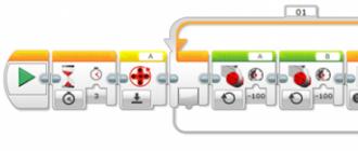
Node diagram. The scheme of such a node is very simple and easy to implement. The cost is only 1 dollar. Two lm317 chips. The first is connected according to the current stabilizer circuit, the second stabilizes the output voltage.
So, we know that about 120 milliamps of current will flow through the circuit. This is not a very large current, so there is no need to install a heat sink on the microcircuit. Such a system works quite simply. During charging, a voltage drop is formed across the resistor r1, which is enough for the LED to light up and, as the charge progresses, the current in the circuit will drop. After a certain voltage drop across the transistor, the LED will simply go out. Resistor r2 sets the maximum current. It is desirable to take it at 0.5 watts. Although it is possible and at 0.25 watts. From this link you can download the program for calculating the microcircuit.


This resistor has a resistance of about 10 ohms, which corresponds to a charging current of 120 milliamps. The second part is the threshold node. It stabilizes the voltage; the output voltage is set by selecting resistors r3, r4. For the most accurate setting, the divider can be replaced with a 10 kilo-ohm multi-turn resistor.
The voltage at the output of the unmodified charger was about 26 volts, despite the fact that the test was carried out at a 3 watt load. The battery, as mentioned above, is 18 volts. Inside are 15 1.2 volt nickel-cadmium cans. The voltage of a fully charged battery is about 20.5 volts. That is, at the output of our node, we need to set the voltage within 21 volts.

Now let's check the assembled block. As you can see, even with the output shorted, the current will not exceed 130 milliamps. And this is regardless of the input voltage, that is, the current limit works as it should. We mount the assembled board in the docking station. As an indicator of the end of the charge, we will put the native LED of the docking station, but with a transistor it is no longer needed.
The output voltage is also within the specified range. Now you can connect the battery. The LED lights up, charging has begun, we will wait for the process to complete. As a result, we can say with confidence that we have definitely improved this charge. The battery does not heat up, and most importantly, it can be charged as much as you like, since the device automatically turns off when the battery is fully charged.
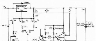
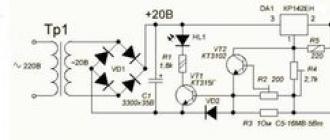
Hello dear visitors. I want to offer a simple charger circuit for sealed screwdriver batteries. The scheme is shown in Figure 1.
The basis of the circuit is a three-terminal integrated adjustable positive voltage stabilizer KR142EN12A. The stabilizer allows operation with load current up to 1.5A. This parameter limits the maximum battery charge current.
The scheme works as follows. An alternating voltage of 12.6 - 13V, taken from the secondary winding of the mains transformer, is rectified by a diode bridge VD1 - D3SBA40. It can be replaced by RC201, RS201, KBP005, BR305, KBPC1005, or a bridge can be assembled from individual diodes with a direct rectified current of at least two amperes. At the output of the rectifier there is a filter capacitor C1, which reduces the ripple of the rectified voltage. There is already a constant voltage on the capacitor equal to the amplitude value of the alternating voltage 12.6 ... 13V. Those. 12.6 √2 ≈ 17.7V. This voltage will be if ready-made incandescent transformers are used as a mains transformer, for example, TN17, TN18, TN19 with the appropriate connection of the secondary windings. I have a transformer - rewound TVK-110L1. The operating voltage of its secondary winding is 14V.
From the rectifier, the voltage is supplied to the integral stabilizer DA1, the output voltage of which is set using the resistor R4 at the level required for your particular battery. For example, you know that the voltage of a fully charged battery is 14.1V, then this voltage must be set at the output of the stabilizer. Resistor R3 serves as the charging current sensor, in parallel with which a tuning resistor R2 is connected, using this resistor, the charging current limiting level is set, which is equal to 0.1 of the battery capacity. The power dissipated on the resistor R3 is equal to I2 charge R3 = 1.52 1 = 2.25W, so you can use a two-watt resistor with a nominal value of 1 ohm, but the charging current must be slightly reduced. In general, this circuit is a voltage regulator with load current limitation. At the first stage, the battery is charged with a stable current, then, when the charge current becomes less than the limiting current, the battery will be charged with a decreasing current to the stabilization voltage of the DA1 microcircuit.
The charging current sensor for the HL1 indicator is the diode VD2. In this case, the HL1 LED will indicate the passage of current up to,? 50 milliamps. If the same R3 is used as a current sensor, then the LED will go out already at a current of ≈0.6A, i.e. the end of battery charging, judging by the extinguished LED, would have come too soon. The battery would not be fully charged. This device can also charge six-volt batteries. By the way, you can figure out whether it is possible to charge batteries with a voltage of 1.25V. The voltage at the input of the stabilizer DA1 is 20V, the charge current is allowable - 1.5A. the initial voltage on the battery is one volt, which means that in this case 20V - 1V = 19V will drop on the microcircuit. At the same time, a power equal to U I \u003d 19V 1.5A \u003d 28.5W will be released on it. The maximum allowable power dissipation for KR142EN12A is 30W. Those. provided that an appropriate heatsink is used, it is also possible to charge a separate battery cell with a voltage of 1.25V. The radiator area for a given power can be estimated from the diagram.

The charger is assembled on a printed circuit board, the drawing of which can be downloaded here. The specific details I applied are shown in photo1. Well, I think that with the layout of the board in lau format, you can apply other components by changing the pattern of the conductors. If you use TVK-110L1 as a network transformer, then the primary winding can be left completely, i.e. 3000 turns. So, in this case, the number of turns per volt will be equal to W1volt = W1/U1 = 3000/220 ≈ 13.7. The number of turns of the secondary winding will be equal to W2 = U2 W1volt = 12.6 13.7 ≈ 173 turns. Wire diameter D = 0.7√I = 0.7 √1 = 0.7mm - for a charge current of 1A. If the secondary winding is not removed in the core window, then you will have to sacrifice a small no-load current of the transformer and recalculate the number of turns of the primary winding for a different coefficient. We consider. The cross-sectional area of the TVK-110L1 core Sc = 6.4 cm2 (SHL20 × 32), W1volt = 50/Sc = 50/6.4 ≈ 8 turns per volt, then the number of turns of the primary winding will be 220 8 = 1760 turns. You will have to wind 3000 - 1760 = 1240 turns. Well, you can count the secondary winding yourself. If you have any questions, then I have a request, ask them on the forum. Perhaps the answers to them will be of interest to other visitors to the site. Goodbye. K.V.Yu.
Download the scheme and drawing of the printed circuit board.