A screwdriver is a tool that almost every home craftsman has. Like other electrical appliances, it requires a connection to the network or accumulates a charge. The last option is the most common. Removable battery requires charger. Usually it is in the kit. However, like any other device, charging for a screwdriver is not immune from breakage. To restore the tool to working capacity, you will have to purchase a replacement or make it yourself.
Kinds
There are many chargers suitable for certain brands and models of tools. All of them can be divided into main types.
Analog with built-in power supply
 Analog with built-in power supply - quite in demand. This explained by the low cost. Usually they do not belong to professional equipment, they quickly fail and "there are not enough stars from the sky." The minimum task, which, as a rule, is set by their manufacturers is to obtain a constant voltage and current load necessary for operation.
Devices work on the principle of a stabilizer. You can do it yourself using the diagram below. To work, you need to remember:
- The voltage at the output of the charging unit is greater than the battery rating.
- Suitable for any type of battery.
- You can use a regular circuit board.
- Such stabilizers apply the compensation principle: unnecessary energy, heat is removed. To dissipate it, you can take, for example, a copper radiator. Area - 20 cm².
- The input transformer (Tr1) changes the voltage from 220 to 20 V. Its power is determined by the current and voltage at the output.
- The current is rectified by a diode bridge (VD1).
- You can borrow the solution of manufacturers: the assembly of Schottky diodes.
- After rectification, the current is pulsating, which is harmful. For smoothing, an electrolytic capacitor (C1) is needed.
- KR142EN is used as a stabilizer. For 12 V, its index is 8B.
- Management - based on a transistor (VT2) and resistors (tuning).
- Automatic shutdown after charging is usually not provided. You will have to determine the required time yourself. Alternatively, you can use a circuit that includes a diode (VD2), a transistor (VT1). After charging, the LED (HL1) goes out. There are more serious options with a switch and an electronic key that turn off automatically.
If the tool is budget, the circuit of its “native” charger may be simpler. It is not surprising that such products quickly fail. Sometimes a relatively new screwdriver is left without charging. Using the scheme discussed above, you can responsibly approach the issue and the device will most likely last longer than the purchased one. Suitable transformer and stabilizer are determined individually for a particular screwdriver.
Analog with an external unit, as the name implies, consists of:

Block - regular, includes:
- transformer;
- diode bridge;
- rectifier;
- capacitor filter.
Factory builds usually don't have a heatsink. Its role can be played by a high power resistor. One of the typical causes of breakdowns is in thermal conditions.
To fix the situation, you first need to find out if the power supply is working. If it functions, it is supplemented with a control scheme, if not, another one is sought. It is quite suitable, for example, from a laptop. It has 18V output, which is quite enough. The rest of the details are usually easy to find. They cost very little, you can borrow from other equipment.
The control block diagram is shown below. The transistor KT817 is used, for amplification - KT818. Need a radiator. The approximate area is 30-40 cm². Up to 10 W will be dissipated here
Many Chinese manufacturers are trying to save on literally every little thing. This should be avoided if more or less decent quality is needed. In a homemade circuit, there is a 1 kOhm trimmer. It is needed to accurately set the current. The output is a 4.7 ohm resistor. It dissipates heat. LED will notify you when charging is complete
The resulting control board is about the size of a matchbox. It fits perfectly in the factory box. There is no need to take out the radiator for the transistor. Enough air movement inside the case
Pulse
Analog devices take a long time to charge: an average of 3-5 hours. Although for domestic purposes it is not scary. Another thing is the professional sphere, where “time is money”. There is such production - accordingly, in a set usually two accumulators.
 Professionals often use pulse chargers. They are have an intelligent process control scheme. Full charge time is impressive: about one hour. Of course, you can make the same fast analog charger, but then its weight and dimensions will be impressive.
Pulse devices are compact and safe. High quality requires a thoughtful, complex scheme. However, you can repeat it. The circuit below is suitable for NiCd batteries with a third signal pin.
The well-known MAX713 controller is used. Input voltage -25 V. Power supply - simple, so his schema is not here.
The resulting charger for a screwdriver "is distinguished by intelligence and ingenuity." It checks the voltage and turns on the boost charge mode. The battery is ready in about 1-1.5 hours. The scheme allows you to choose:
- charge voltage;
- Battery Type.
It indicates the value of the resistor (R 19) for switching modes and the position of the jumpers. Using the proposed drawing, you can repair the breakdown. An additional incentive will be a financial issue. Saving at least twice.
Charging with a defective battery
Sometimes it happens that the screwdriver itself works, but the battery is broken. There are several options for solving the problem:

Models with different voltage
It is not enough to decide on the type of charger and the brand of the manufacturer; to purchase, you also need to know the voltage of your screwdriver. The most common options are 12, 14 and 18 V.
12 V chargers
 The circuit may consist of transistors up to 4.4 pF. This can be seen on the charger diagram for a 12 volt screwdriver. Conductivity in the circuit - 9 microns. Capacitors needed to control clock spikes. The resistors used are usually field resistors. Tetrode chargers have an additional phase resistor. It protects against electromagnetic vibrations.
12V chargers work with resistance up to 30 ohms. Often they can be found on 10 mAh batteries. Among well-known manufacturers, Makita is more often used.
14 V chargers
The diagram shows that five transistors are needed for charging at 14 V. Other features of the circuit:
- the microcircuit is suitable only for four-channel;
- capacitors - impulse;
- tetrodes are needed to work with 12 mAh batteries;
- two diodes;
- conductivity - about 5 microns;
- the average capacitance of the resistor is not more than 6.3 pF.
Devices created according to the scheme can withstand current up to 3.3 A. Triggers are rarely included in the circuit. The exception is Bosch products. For Makita products, flip-flops are successfully replaced with wave resistors.
Chargers for 18 V
The 18 volt screwdriver charger uses only transition-type transistors in the circuit. Other product features include:
- three capacitors;
- tetrode and diode bridge;
- grid trigger;
- current conductivity is about 5.4 microns, sometimes chromatic resistors are used to increase it.
The use of high-conductivity transceivers is a feature of the domestic company Interskol. The current load can reach up to 6 A. Makita often uses high quality dipole transistors in its models.
Whichever manufacturer of screwdriver is chosen, the problem of replacing the charger can be easily solved. To do this, it is enough to at least know some of the features of your instrument.
Their average capacity is 12 mAh. In order for the device to always remain in working condition, you need a charger. However, in terms of voltage, they are quite different.
Nowadays, models for 12, 14 and 18 V are produced. It is also important to note that manufacturers use various components for chargers. In order to understand this issue, you should look at the standard charger circuit.
Charging scheme
The standard electrical circuit of the screwdriver charger includes a three-channel type microcircuit. In this case, four transistors are required for a 12 V model. In terms of capacity, they can vary quite a lot. In order for the device to cope with a high clock frequency, capacitors are attached to the microcircuit. They are used for charging both pulsed and transitional types. In this case, it is important to take into account the characteristics of specific batteries.
Thyristors are directly used in devices for current stabilization. Some models have open type tetrodes. According to the current conductivity, they differ from each other. If we consider modifications to 18 V, then there are often dipole filters. These elements make it easy to deal with network congestion.

Modifications for 12V
A 12 V screwdriver (the circuit is shown below) is a set of transistors with a capacity of up to 4.4 pF. In this case, the conductivity in the circuit is provided at the level of 9 microns. Capacitors are used to ensure that the clock frequency does not increase sharply. Resistors in models are used mainly field.
If we talk about charging on tetrodes, then there is an additional phase resistor. It copes well with electromagnetic vibrations. Negative resistance with 12 V charges is maintained at 30 ohms. They are most often used for 10 mAh batteries. To date, they are actively used in models of the Makita trademark.

14V chargers
The charger circuit for a 14 V transistor screwdriver includes five pieces. Directly, the microcircuit for converting current is only suitable for a four-channel type. Capacitors for 14 V models are pulsed. If we talk about batteries with a capacity of 12 mAh, then tetrodes are additionally installed there. In this case, there are two diodes on the microcircuit. If we talk about the charging parameters, then the current conductivity in the circuit, as a rule, fluctuates around 5 microns. On average, the capacitance of the resistor in the circuit does not exceed 6.3 pF.
Directly, 14 V charging current loads can withstand 3.3 A. Triggers in such models are installed quite rarely. However, if we consider Bosch screwdrivers, then they are often used there. In turn, for Makita models, they are replaced by wave resistors. In order to stabilize the voltage, they fit well. However, the frequency of charging can vary greatly.
Model diagrams for 18 V
At 18 V, the screwdriver charger circuit assumes the use of only transition type transistors. There are three capacitors on the chip. The tetrode is directly installed with a grid trigger used in the device to stabilize the limiting frequency. If we talk about charging parameters at 18 V, then it should be mentioned that the current conductivity fluctuates around 5.4 microns.
If we consider charging for Bosch screwdrivers, then this figure may be higher. In some cases, chromatic resistors are used to improve signal conductivity. In this case, the capacitance of the capacitors should not exceed 15 pF. If we consider chargers of the Interskol trademark, then they use transceivers with increased conductivity. In this case, the maximum current load parameter can reach up to 6 A. In the end, mention should be made of Makita devices. Many of the battery models are equipped with high-quality dipole transistors. With increased negative resistance, they cope well. However, problems in some cases arise with magnetic oscillations.
Chargers "Intreskol"
The standard charger of the Interskol screwdriver (the diagram is shown below) includes a two-channel microcircuit. Capacitors are selected for her all with a capacity of 3 pF. In this case, transistors for 14 V models are used as pulse type. If we consider modifications to 18 V, then there you can find variable analogues. The conductivity of these devices can reach up to 6 microns. In this case, the batteries are used on average at 12 mAh.

Scheme for the model "Makita"
The charger circuit has a three-channel type chip. There are three transistors in the circuit. If we talk about 18 V screwdrivers, then in this case, capacitors are installed with a capacity of 4.5 pF. Conductivity is provided in the region of 6 microns.
All this allows you to remove the load from the transistors. Directly tetrodes are used open type. If we talk about modifications to 14 V, then the charges are available with special triggers. These elements allow you to perfectly cope with the increased frequency of the device. At the same time, they are not afraid of jumps in the network.

Bosch screwdriver chargers
The standard Bosch screwdriver includes a three-channel type chip. In this case, the transistors are of the pulse type. However, if we talk about 12 V screwdrivers, then transitional analogues are installed there. On average, they have a bandwidth of 4 microns. Capacitors in devices are used with good conductivity. There are two diodes in the chargers of the presented brand.
Triggers in devices are used only at 12 V. If we talk about the protection system, then transceivers are used only in an open type. On average, they are able to carry a current load of 6 A. In this case, the negative resistance in the circuit does not exceed 33 Ohms. If we talk separately about 14 V modifications, then they are produced for 15 mAh batteries. Triggers are not used. There are three capacitors in the circuit.

Scheme for the model "Skill"
The charger circuit includes a three-channel microcircuit. In this case, the models on the market are presented at 12 and 14 V. If we consider the first option, then the transistors in the circuit are used of a pulsed type. Their current reducibility is no more than 5 microns. In this case, triggers are used in all configurations. In turn, thyristors are used only for charging at 14 V.
Capacitors for 12 V models are installed with a varicap. In this case, they are not able to withstand large overloads. In this case, the transistors overheat quite quickly. There are three diodes directly in charging at 12 V.
Application of LM7805 Regulator
The charger circuit for a screwdriver with an LM7805 regulator includes only two-channel microcircuits. Capacitors are used on it with a capacity of 3 to 10 pF. You can most often meet regulators of this type with models of the Bosch brand. Directly for charging at 12 V, they are not suitable. In this case, the negative resistance parameter in the circuit reaches 30 ohms.
If we talk about transistors, then they are used in models of a pulse type. Triggers for regulators can be used. There are three diodes in the circuit. If we talk about modifications to 14 V, then tetrodes are only suitable for them of the wave type.
Using transistors BC847
The BC847 transistorized screwdriver charger circuit is quite simple. These elements are used most often by Makita. They are suitable for 12 mAh batteries. In this case, microcircuits are used three-channel type. Capacitors are used with dual diodes.
The triggers themselves are open-type, and their current conductivity is at the level of 5.5 microns. In total, three transistors are required for charging at 12 V. One of them is installed at the capacitors. The rest in this case are behind the reference diodes. If we talk about voltage, then charging at 12 V overloads with these transistors is capable of transferring 5 A.

IRLML2230 transistorized device
Charging circuits with transistors of this type are quite common. The company "Intreskol" uses them in versions for 14 and 18 V. In this case, microcircuits are used only three-channel type. Directly, the capacitance of these transistors is 2 pF.
They tolerate current overloads from the network well. In this case, the conductivity indicator in charging does not exceed 4 A. If we talk about other components, then capacitors are installed of a pulse type. In this case, you need three. If we talk about 14 V models, then they have thyristors for voltage stabilization.
A screwdriver is one of the most versatile power tools. Many people have experienced this.
However, even such a wonderful tool has its drawbacks. One of them is a charger. When it breaks, it can be difficult to find a suitable one for the model you need. And even if there is one, the price is high, and it's easier to buy a new screwdriver. Another problem can be slow battery charging.
Many users decide to make a charger with their own hands. In this article, you will learn what is needed for this, and how to make such a device for 12 and 18 volts.
Homemade screwdriver charger
Before starting work, you need to determine what type of battery your screwdriver is using. They are lead, nickel, lithium, others. Depending on the type of battery, different designs of chargers are needed. After all, each battery has its own characteristics and operating rules.
Lithium-ion batteries are the most commonly used today. Batteries of this kind are considered the safest and most environmentally friendly. When using them, you need to accurately consider the voltage. Increasing or decreasing the voltage dramatically reduces the duration and capacity of such batteries.
Carefully! Heating a lithium-ion battery above 60 degrees can cause a fire or even an explosion.
Before you get started, make sure that you have all the necessary knowledge in the field of electrical circuits and soldering.
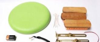
For work you will need:
- charging glass;
- a battery that doesn't work;
- knife and blades;
- drill;
- soldering iron;
- wires with a length of at least 15 cm;
- screwdriver;
- thermal gun.
Most often there are screwdrivers that use batteries with a voltage of 12 and 18 volts.
To do the alteration of the charger, you need to understand the design. The unit consists of a current generator on a composite transistor, which receives current from the rectifier bridge. It, in turn, is connected to a step-down transformer with the required output voltage.
It is necessary that the transformer produces the necessary power. This is important for the continued operation of the device. Otherwise, it will burn out. The current is regulated by a resistor when the battery is inserted. The current is constant during the entire charge. And the higher the power of the transformer, the more stable the charge.
DIY 12 volt screwdriver charger
Such a unit is suitable for lithium-ion batteries from 900 mAh and more. To make it, you need to follow these steps:
- First you need to take the charging glass and carefully open it.
- After that, peel off the terminals and all electronics with a soldering iron.
- Then you need to unsolder the terminals from the plus and minus in the non-working battery, again using the soldering iron. In order not to confuse the polarity, mark the pros and cons with a marker or pen.
- In the disassembled charging glass, you need to mark where the wires will be.
- Then you need to drill holes. The diameter can be increased using a knife.
- After that, the wires are inserted into the holes drilled under them and soldered to the prepared glass, while observing the polarity.
- Using a thermal gun, attach the battery cover to the charging cup.
- And at the end of all the operations done, the bottom cover is attached back to the charging glass.
So you yourself made a charger.
Charging for a 18 volt screwdriver with your own hands

You can make an 18 volt charger according to the scheme described above. If the native block is in good condition, you can use it for rework. If not, you can take the power supply from the laptop as a basis. It puts out just the right 18 volts.
You can make the unit according to the scheme, often found on the Internet. This alteration allows you to speed up the charging time of the battery. According to the scheme, the current flows into the battery, and the control is carried out using a transistor. It affects the indicator readings. Then the current decreases as it charges, and the LED goes out.
As you can see, the device is far from the most complicated. Any master can improve the charging unit for his screwdriver. Thus, you will make the charger more reliable, with the possibility of accelerated recharging of batteries.
There is a screwdriver in every home where elementary repairs are performed. Any electrical appliance requires stationary electricity or a power supply. Since cordless screwdrivers are the most popular, a charger is also required.
- 1 Types of chargers
- 1.1 Analog with built-in power supply
- 1.2 Analog with external power supply
- 1.3 Pulse
- 2 Power supply for a screwdriver - diagram and assembly procedure
- 2.1 How to use the appliance
It comes with a drill, and like any electrical appliance can fail. So that you do not encounter the problem of non-working equipment, we will study a general description of chargers for a screwdriver.
Types of chargers
Analog with built-in power supply
Their popularity is due to their low cost. If the drill (screwdriver) is not intended for professional use, the duration of work is not the very first question. The task of a simple charger is to obtain a constant voltage with a current load sufficient to charge the battery.
Important! To start charging, the voltage at the output of the power supply must be higher than the nominal value of the battery.
Such charging works on the principle of a conventional stabilizer. For example, consider a charger circuit for a 9-11 volt battery. The type of batteries doesn't matter.
Such a power supply (aka charger) can be assembled with your own hands. You can solder the circuit on a universal circuit board. To dissipate the heat of the stabilizer microcircuit, a copper radiator with an area of 20 cm² is sufficient.
Pay attention Stabilizers of this type work according to the compensation principle - excess energy is removed in the form of heat.
The input transformer (Tr1) lowers the 220 volt alternating voltage to 20 volts. The power of the transformer is calculated from the current and voltage at the output of the charger. Further, the alternating current is rectified using the diode bridge VD1. Usually manufacturers (especially Chinese ones) use an assembly of Schottky diodes.

After rectification, the current will be pulsating, this is harmful to the normal functioning of the circuit. The ripples are smoothed out by a filtering electrolytic capacitor (C1).
The role of the stabilizer is performed by the KR142EN chip, in amateur radio slang - “roll”. To obtain a voltage of 12 volts, the microcircuit index must be 8B. The control is assembled on a transistor (VT2) and trimmers.
Automation on such devices is not provided, the battery charging time is determined by the user. To control the charge, a simple circuit was assembled on a transistor (VT1) and a diode (VD2). When the charge voltage is reached, the indicator (LED HL1) goes out.
More advanced systems incorporate a switch that turns off the voltage at the end of the charge in the form of an electronic key.
Complete with economy class screwdrivers (produced in the Middle Kingdom), there are chargers and simpler ones. No wonder the failure rate is quite high. The owner has the prospect of being left with a relatively new, inoperable screwdriver. According to the attached scheme, you can assemble a charger for a screwdriver with your own hands, which will last longer than the factory one. By changing the transformer and stabilizer, you can choose the right value for your battery.
Analog with external power supply
By itself, the charger circuit is as primitive as possible. The kit includes a mains power supply, and the charger itself, in the case of the battery module retainer.

There is no point in considering the power supply, its circuit is standard - a transformer, a diode bridge, a capacitor filter and a rectifier. The output is usually 18 volts, for classic 14 volt batteries.
The charge control board occupies the area of a matchbox:

As a rule, there is no heat sink on such assemblies, except perhaps a high power load resistor. Therefore, such devices often fail. The question arises: how to charge a screwdriver without a charger?
The solution is simple for a person who knows how to hold a soldering iron in his hands.
- The first condition is the presence of a power source. If the "native" unit is working, it is enough to assemble a simple control circuit. In case of failure of the entire kit, you can use the power supply for the laptop. The required output is 18 volts. The power of such a source is enough for the eyes for any set of batteries
- The second condition is elementary skills in assembling electrical circuits. The parts are the most affordable, you can solder them from old household appliances, or buy them on the radio market literally for a penny.
Schematic diagram of the control unit: 
At the input is a 18 volt zener diode. The control circuit is based on a KT817 transistor, the amplification is provided by a powerful KT818 transistor. It must be equipped with a radiator. Depending on the charge current, it can dissipate up to 10 watts, so you need a radiator with an area of 30-40 cm².
It is the savings "on matches" that makes Chinese chargers so unreliable. A 1 KΩ trimmer is needed to accurately set the charge current. The 4.7 ohm resistor at the output of the circuit should also dissipate enough heat. Power not less than 5 watts. The LED indicator will notify the end of the charge, it will turn off.
The assembled circuit is easy to place in the standard charging case. It is not necessary to take out the transistor radiator, the main thing is to ensure air circulation inside the case.
The savings lies in the fact that the power supply from the laptop is still used for its intended purpose.
Important! A common disadvantage of analog chargers is the long charging process.
For a household screwdriver, this is not scary. I left it to charge overnight before starting work - enough to assemble the cabinet. The average charge time for a Chinese cordless drill is 3-5 hours.
Pulse
Let's move on to heavy weapons. Professional screwdrivers are used intensively, and downtime due to a dead battery is unacceptable. We omit the price issue, any serious equipment is expensive. Especially since there are usually two batteries in the kit. While one is in operation - the second is on recharging.
The switching power supply, complete with an intelligent charge control circuit, fills the battery by 100% in just 1 hour. You can also assemble an analog charger with the same power. But its weight and dimensions will be comparable to a screwdriver.
All these shortcomings are deprived of impulse chargers. Compact size, high charge currents, thoughtful protection. There is only one problem: the complexity of the circuit, and as a result, the high price.
However, such a device can also be assembled. Saving at least 2 times.
We offer an option for "advanced" nickel-cadmium batteries equipped with a third signal contact.
The circuit is assembled on the popular MAX713 controller. The proposed implementation is designed for an input voltage of 25 volts DC. It is not difficult to assemble such a power supply, so we omit its circuit.

The charger is intelligent. After checking the voltage level, the accelerated discharge mode starts (to prevent the memory effect). Charging takes 1-1.15 hours. A feature of the circuit is the ability to select the charge voltage and battery type. The description in the figure indicates the position of the jumpers and the value of the resistor R19 for changing modes.
If the branded charging of a professional screwdriver fails, you can save on repairs by assembling the circuit yourself.
Screwdriver power supply - diagram and assembly procedure
Many are familiar with the situation: the screwdriver is alive and well, and the battery pack ordered to live a long time. There are many ways to restore the battery, but not everyone likes to mess with toxic elements.
How to use the electrical appliance
The answer is simple: connect an external power supply. If you have a typical Chinese device with 14.4 volt batteries, you can use a car battery (handy for working in a garage). And you can pick up a transformer with an output of 15-17 volts, and assemble a full-fledged PSU.

The set of parts is the most inexpensive. Rectifier (diode bridge) and thermostat for overheat protection. The remaining elements have a service task - an indication of the input and output voltage. No stabilizer required - your screwdriver's electric motor is not as demanding as the battery.
Note As you can see, reviving a cordless drill is not so difficult. The main thing is not to make a hasty decision: “throw away and buy a new electrical appliance”
If your screwdriver batteries are completely out of order, then you can convert it to a network one, see how to make such a power supply in this video
Here you can download the printed circuit board in lay format
This is how the charger conversion scheme looks like. 
The use of power tools greatly facilitates our work and reduces assembly time. Currently, battery-operated screwdrivers have gained great popularity. In the framework of this article, we will consider a diagram of a typical charger for a screwdriver. As well as repair tips and options for amateur radio designs.

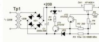
The power part of the screwdriver charger is a power transformer of the GS-1415 type, designed for a power of 25 watts.

A reduced alternating voltage with a nominal value of 18V is removed from the secondary winding of the transformer; it follows from 4 diodes VD1-VD4 type 1N5408, through a fuse. Diode bridge. Each 1N5408 semiconductor element is rated for forward current up to three amps. The electrolytic capacitance C1 smooths out the ripples that appear in the circuit after the diode bridge.
Management is implemented on a microassembly HCF4060BE, which combines a 14-bit counter with the components of the master oscillator. It controls type S9012. It is loaded on relay type S3-12A. Thus, a timer is implemented in circuitry, which turns on the relay for a battery charge time of about an hour. When the charger is turned on and the battery is connected, the relay contacts are in the normally open position. The HCF4060BE is powered by a 1N4742A at 12 volts, since the rectifier output is about 24 volts.
When the "Start" button is closed, the voltage from the rectifier begins to follow to the zener diode through the resistance R6, then the stabilized voltage goes to the 16th output of U1. The transistor S9012 opens, which is controlled by the HCF4060BE. The voltage through the open transitions of the transistor S9012 follows the relay winding. The contacts of the latter are closed, and the battery begins to charge. The protective diode VD8 (1N4007) shunts the relay and protects VT from a reverse voltage surge that occurs when the relay winding is de-energized. VD5 prevents the battery from discharging when the mains voltage is turned off. With the opening of the contacts of the "Start" button, nothing will happen because the power goes through the diode VD7 (1N4007), the zener diode VD6 and the quenching resistor R6. Therefore, the microcircuit will receive power even after the button is released.
Interchangeable typical battery from a power tool assembled from separate series-connected nickel-cadmium Ni-Cd batteries, each 1.2 volts, so there are 12 of them. The total voltage of such a battery will be about 14.4 volts. In addition, a temperature sensor has been added to the battery pack - SA1 it is glued to one of the Ni-Cd batteries and fits snugly against it. One of the terminals of the thermostat is connected to the battery negative. The second output is connected to a separate, third connector.
When the "Start" button is pressed, the relay closes its contacts, and the battery charging process begins. The red LED lights up. An hour later, the relay breaks the battery charge circuit of the screwdriver with its contacts. The green LED lights up and the red LED goes out.
The thermal contact monitors the temperature of the battery and breaks the charge circuit if the temperature is above 45°. If this happens before it works, this indicates the presence of a "memory effect".
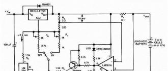
The basis of the design is an adjustable positive voltage stabilizer. It allows operation with a load current of up to 1.5A, which is quite enough to charge the batteries.

An alternating voltage of 13V is taken from the secondary winding of the transformer, rectified by a diode bridge D3SBA40. At its output is a filter capacitor C1, which reduces the ripple of the rectified voltage. From the rectifier, a constant voltage is supplied to the integrated stabilizer, the output voltage of which is set by the resistance of the resistor R4 at the level of 14.1V (Depends on the type of screwdriver battery). The charging current sensor is the resistance R3, in parallel to which the tuning resistor R2 is connected, with the help of this resistance the level of the charging current is set, which corresponds to 0.1 of the battery capacity. At the first stage, the battery is charged with a stable current, then, when the charging current becomes less than the limiting current, the battery will be charged with a lower current to the stabilization voltage DA1.

The charging current sensor for the HL1 LED is VD2. In this case, HL1 will indicate current up to 50 milliamps. If R3 is used as a current sensor, the LED will turn off at 0.6A, which would be too early. The battery would not have time to charge. This device can also be used for six-volt batteries.