This article shows different options for controlling relays in arduino sketches. The examples were tested on the Arduino Uno, but they can be easily applied to other Arduino boards: Uno, Mega, Nano.
Wiring diagram
In this example, a standard one is used, on which all the necessary elements for connecting to are already installed. The connection diagram is very simple: the relay module is connected to pin 5 of the Arduino board. At the same time, for simplicity, we can not even connect a real load - the relay will click with each state change, we will hear these clicks and we will understand that the sketch is working.
Sketch for working with relays
/* * Sketch for relay control using arduino * Use SONGLE SRD-05VDC relay * Relay OPEN when LOW signal is applied to the control pin. * Relay CLOSE when HIGH signal is applied to the control pin. * * In this example, we simply open and close the relay every 5 seconds. * * PIN_RELAY contains the pin number to which the relay is connected, which we will control * * In the setup function, set the initial position of the relay (closed) * If a load (for example, a light bulb) is connected to the relay, then after starting the sketch, it will turn on and off every 5 seconds * * To change the blinking period, you need to change the parameter of the delay() function: by setting 1000 milliseconds, you get 1 second of delay * * In real projects, the relay turns on in response to the detection of any external events through the connection of sensors * */ #define PIN_RELAY 5 // Define the pin used to connect the relay // In this function, define the initial settings void setup() ( pinMode(PIN_RELAY, OUTPUT); // Declare the relay pin as an output digitalWrite(PIN_RELAY, HIGH); // Turn off the relay - send high signal ) void loop() ( digitalWrite(PIN_RELAY, LOW); // Turn on the relay - send a low signal level delay(5000); digitalWrite(PIN_RELAY, HIGH); // Turn off the relay - send a high signal delay(5000); )Relay control sketch with motion sensor
In real projects, the change in the state of the relay should occur in response to some reaction of the environment. For example, in response to a signal from a triggered motion sensor, you can turn on the light by closing the circuit using a relay. In this sketch, we will consider such a connection option.
Relay connection diagram

It should be understood that in real projects they do without an arduino at all - simply by connecting the signal output of the sensor to the relay.
Sketch example
In this example, we will add a PIR status check to the loop using the digitalRead() function. If we get HIGH, then this means the sensor is triggered and we perform an action - turn on the relay. If you attach a light bulb to it, it will light up. But, as in the previous example, you can just listen for clicks.
/* Sketch for controlling an Arduino relay using a PIR sensor PIN_RELAY contains the number of the pin to which the relay is connected, which we will control PIN_PIR contains the number of the pin with the connected PIR sensor In the setup function, set the initial position of the relay (closed) In the body of the loop function, check for the presence high signal level from the sensor using the digitalRead function To debug the current value of the sensor, display the current value of the sensor in the port monitor */ #define PIN_RELAY 8 // Define the pin used to connect the relay #define PIN_PIR 5 // Define the pin used to connect the PIR sensor / / In this function, we define the initial settings void setup() ( Serial.begin(9600); pinMode(PIN_RELAY, OUTPUT); // Declare the relay pin as an output digitalWrite(PIN_RELAY, HIGH); // Turn off the relay - send a high signal ) void loop() ( int val = digitalRead(PIN_PIR); // Read the value from the motion sensor into a separate variable if (val == HIGH) ( Serial. println("Sensor triggered"); digital Write(PIN_RELAY, LOW); // Turn on the relay - send a low signal level ) else ( digitalWrite(PIN_RELAY, HIGH); // Turn off the relay - send a high signal level ) delay(1000); // Check values once per second. )
/*
*
* ArduinoKit Experiment Kit
* Program code for experiment No. 13: sketch 13
*
* Relay
*
* Written for http://site
*
*
* Help from the Arduino community.
* Visit http://www.arduino.cc
*
*
*
* USING A TRANSISTOR TO CONTROL A RELAY
*
* A relay is an electrically controlled mechanical switch.
* Relay can handle much more voltage and current than ports
* An Arduino, or let's say a transistor, included in the kit. If
* you want to use an Arduino to control an incandescent lamp,
* coffee maker or other electronic device powered by 220V,
* Relay is a great way to do this.
* The relay can easily cope with switching, switching, large
* voltages much higher than the Arduino port can offer.
* We will use a transistor to drive a relay,
* just like we used the transistor to drive
* engine in experiment No. 12 (Starter kit, programmer and robotics).
*
* The relay consists of a coil, wire, metal core and
* switching contacts. When power is applied to the coil, the core
* magnetized, and attracts the anchor (lever), thereby
* toggles contacts. Since the relay contacts are completely isolated
* from Arduino, you can safely use the relay to control
* dangerous voltage, BUT! Please do so if you are already
* know and know how to work safely with high voltage!
*
* The relay has three contacts, - COM (common), NC (normally closed)
* and NO (normally open). When the relay is off, COM output
* connected to the NC (normally closed) terminal, and when enabled,
* COM pin is connected to NO (normally open).
*
* This code is very simple - it turns on the relay for one second, then
* turns off, waits a second and turns on again, as in the experiment with a blinking
* LED!
*
* Equipment connection:
*
* Transistor:
* The transistor has three outputs. Looking at the flat side
* pins down, the pin assignments are as follows (left
* on the right): COLLECTOR, BASE, EMITTER.
*
* Connect the BASE through a 1K resistor to digital port 2.
*
* Connect EMITTER to ground (GND).
*
* Relay coil:
*
* The relay has coil contacts that can be used to control
* relays and contacts for load control. on the top or
* the lower part of the relay must have a picture, or a symbol,
* indicating coil contacts.
*
* Connect one side of the coil to the collector of the transistor.
*
* Connect the other side of the coil to a +5 Volt supply.
*
* Diode:
*
* The relay has a coil that you energize in order to
* pull anchor. When the power is turned off, the coil generates
* voltage surge that can damage the transistor. This
* The diode protects the transistor from voltage surge.
*
* Connect the diode lead, CATHODE, to the +5 Volt supply.
*
* Connect the other end of the diode, the ANODE, to the COLLECTOR of the transistor.
*
* Relay and LED contacts:
*
* Relay contacts can switch everything that can be turned on or
* turn off, but we will use relay contacts in this lesson
* to turn the LEDs on and off.
*
* Connect the common output of the relay contact group COMMON to the resistor
* 330 Ohm. The second output of the resistor is +5 volts.
*
* Connect the output of the relay contact group NC (normally closed)
* to the positive (long) terminal of LED 1.
*
* Connect the output of the relay contact group NO (normally open)
* to the positive (long) output of the second LED - LED 2.
*
* Connect the negative leads (short legs) of both LEDs
* to ground (GND).
*
*
*
* Comment to the program written
* November 26, 2014
* specially for http: // site
*
*
*/
const int relayPin = 2; // port for transistor control
const int timeDelay = 1000; // delay in ms, between on. and off.
// You can reduce the delay time, but note that
// the relay, being a mechanical device, will wear out
// faster if switching frequency is too fast.
void setup()
{
pinMode(relayPin, OUTPUT); // set port as outgoing
}
void loop()
{
digitalWrite(relayPin, HIGH); // enable relay
digitalWrite(relayPin, LOW); // turn off the relay
delay(timeDelay); // pause 1 second
The article describes such an electronic device as a relay, briefly explains the principles of its operation, and also considers connecting a module with a DC relay to Arduino using the example of controlling LEDs.
We will need:
- Arduino UNO (or compatible board);
- personal computer with Arduino IDE or other development environment;
- a module with a relay (for example, such);
- 4 resistors of 220 ohms (I recommend purchasing a set of resistors with values from 10 ohms to 1 megohm);
- 4 LEDs (for example, from such a set);
- connecting wires (like these).
1 Operating principle and types of relays
A relay is an electromechanical device for closing and opening an electrical circuit. In the classic version, the relay contains an electromagnet that controls the opening or closing of contacts. If in the normal position the relay contacts are open, and when the control voltage is applied, they close, such a relay is called closing. If in the normal state the relay contacts are closed, and when the control voltage is applied, they open, this type of relay is called a NC relay.
In addition, there are many other types of relays: switching, single-channel, multi-channel, DC or AC relays, and others.
2 Wiring diagram relay module SRD-05VDC-SL-C
We will use a module with two identical relays of the type SRD-05VDC-SL-C or similar.
The module has 4 connectors: power connectors K1 and K2, a control connector and a connector for external power supply (with a jumper).
Relay type SRD-05VDC-SL-C has three contacts for connecting the load: two extreme fixed ones, and the middle one - switching. It is the middle contact that is a kind of “key” that switches the circuits in one way or another. There is a hint on the module which relay contact is normally closed: the marking "K1" and "K2" connects the middle contact with the leftmost one (pictured). Applying a control voltage to input IN1 or IN2 (low-voltage control connector) will cause the relay to switch the middle contact of the contact group K1 or K2 with the right one (power connector). The current sufficient to switch the relay is about 20mA, the Arduino digital pins can supply up to 40mA.

The external power connector is used to provide electrical isolation between the Arduino board and the relay module. By default, there is a jumper on the connector between the JD-VCC and VCC pins. When it is installed, the module uses the voltage supplied to the VCC pin of the control connector for power, and the Arduino board is not galvanically isolated from the module. If you need to provide galvanic isolation between the module and the Arduino, you must supply power to the module through the external power connector. To do this, the jumper is removed, and additional power is supplied to the JD-VCC and GND pins. At the same time, power is also supplied to the VCC pin of the control connector (from +5 V Arduino).
By the way, the relay can switch not only a low-current load, as in our example. With the help of a relay, you can close and open quite large loads. Which ones - you need to look in the technical description for a specific relay. For example, this SRD-05VDC-SL-C relay can switch networks with current up to 10 A and voltage up to 250 V AC or up to 30 V DC. That is, it can be used, for example, to control the lighting of an apartment.
Where did the relay get its name from?
From the name of the British scientist Lord Rayleigh - 28.6%
From the procedure for changing tired mail horses - 57.1%
From the name of the physical quantity of brightness measurement - 0%
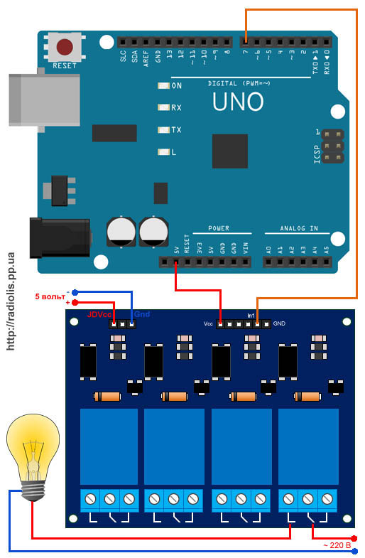
In this example, we do not need a galvanic isolation of the Arduino and the relay module, so we will power the module directly from the Arduino board, and leave the jumper in place. Let's assemble the circuit, as shown in the figure. Resistors used - 220 Ohm, any LEDs.

If the LEDs should never turn off, you can connect the center point of the relay not to the pins D4 And D5 Arduino, but directly to +5 V.
3 Relay control sketch using Arduino
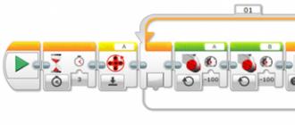
We will alternately light a pair of LEDs of the same color, and every second switch to a pair of a different color. Let's write a sketch like this.
const int relay1 = 2; // control pin of the 1st relay const int relay2 = 3; // control pin of the 2nd relay const int led1 = 4; // switched output - power supply of the 1st LED const int led2 = 5; // switched output - power supply of the 2nd LED void setup() ( pinMode(relay1, OUTPUT); pinMode(relay2, OUTPUT); pinMode(led1, OUTPUT); pinMode(led2, OUTPUT); // set both relays to their original position: digitalWrite(relay1, HIGH); digitalWrite(relay2, HIGH); // supply power to the LEDs: digitalWrite(led1, HIGH); digitalWrite(led2, HIGH); ) void loop() ( // toggle both relays: digitalWrite (relay1, LOW); digitalWrite(relay2, LOW); delay(1000); // switch both relays back: digitalWrite(relay1, HIGH); digitalWrite(relay2, HIGH); delay(1000); )
If you assembled not according to the above scheme, but instead of D4 and D5 connected the central point of the relay directly to the + 5V supply, then from the constants led1 And led2 and all the code associated with them in the sketch can be completely painless to get rid of.
Now let's upload the sketch to the Arduino memory. Here's what it looks like for me. The relays click loudly once a second, and the LEDs blink merrily.

By the way, there are other types of switching devices, for example, optocouplers. These devices do not have mechanical parts, which significantly increases their wear resistance and response speed. In addition, they are smaller and consume less power.
Download technical description (datasheet) relay SRD-05VDC-SL-C
Relays are used to switch various power equipment and other devices using a relatively small voltage. In the classical version, the simplest relay consists of a coil to which a control voltage is applied, and a contact that closes or opens the circuit of the control object. In addition to the control function, the relays also provide protection for the control circuit due to galvanic isolation, since there is a gap between the coil and the contact that does not allow voltage to flow from one circuit to another. Beginning hams who may have recently become familiar with the now popular Arduino board are interested in using relays in their projects but don't know where to start.
Therefore, this material shows the ease of use of Arduino and relays. First of all, it is designed for beginners who get acquainted with Arduino and collect on the basis of this board.
To create a relay circuit, we need an Arduino, one 1KΩ resistor, one 10KΩ resistor, one BC547 transistor, one 6V or 12V relay, one 1N4007 diode, and take a 12V fan as a control object. :

After pressing the button, the fan should turn on and rotate until the button is pressed again. Sketch for such an algorithm:
int pinButton = 8; int Relay = 2; int stateRelay = LOW; int stateButton; int previous = LOW; long time = 0; long debounce = 500; void setup() ( pinMode(pinButton, INPUT); pinMode(Relay, OUTPUT); ) void loop() ( stateButton = digitalRead(pinButton); if(stateButton == HIGH && previous == LOW && millis() - time > debounce) ( if(stateRelay == HIGH)( stateRelay = LOW; ) else ( stateRelay = HIGH; ) time = millis(); ) digitalWrite(Relay, stateRelay); previous == stateButton; )
So how does our scheme work? After pressing the button, the Arduino will put pin 2 in a logic high state, that is, the pin will have a voltage of 5 V. This voltage is used to turn on the transistor, which will turn on the relay, after which our load (in this case, the fan) will be powered by the main power supply.
You can't use the 5V USB port to power the transistor and load because there won't be enough current. Therefore, you need to use an external 7-12V Vcc supply to power both the Arduino and the transistor-relay circuit. The load uses its own power supply. You can, for example, use a lamp as a load and power it from 220 V. And in no case do not connect the Arduino power and the load power!
Now let's complicate our program a little by adding a delay when the relay is turned off. The stayON variable here will be used to set the delay period in milliseconds (default is 5 seconds). As a result, after pressing the button, the relay will turn on and after 5 seconds it will turn off. The code:
int pinButton = 8; int Relay = 2; int stateRelay = LOW; int stateButton; int previous = LOW; long time = 0; long debounce = 500; int stayON = 5000; //5000ms delay void setup() ( pinMode(pinButton, INPUT); pinMode(Relay, OUTPUT); ) void loop() ( stateButton = digitalRead(pinButton); if(stateButton == HIGH && previous == LOW && millis() - time > debounce) ( if(stateRelay == HIGH)( digitalWrite(Relay, LOW); ) else ( digitalWrite(Relay, HIGH); delay(stayON); digitalWrite(Relay, LOW); ) time = millis (); ) previous == stateButton; )
Now, thanks to the information provided in this example, you can safely add relays to your new Arduino projects.
Another fan control circuit using Arduino is possible.
Connecting a powerful load directly to the Arduino, such as a lighting lamp or an electric pump, will not work. The microcontroller does not provide the necessary power to operate such a load. The current that can flow through the Arduino outputs does not exceed 10-15 mA. A relay comes to the rescue, with which you can switch a large current. In addition, if the load is powered by alternating current, for example 220v, then you can’t do without a relay at all. To connect powerful loads to the Arduino via relays, relay modules are usually used.
Depending on the number of switched loads, one-, two-, three-, four- and more-channel relay modules are used.
I bought my one and four channel modules on Aliexpress for $ 0.5 and $ 2.09, respectively.
Module relay device for Arduino, using the example of a 4-channel HL-54S V1.0 module.
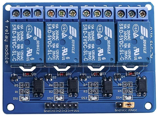
Let us consider in more detail the device of this module, according to this scheme, all multichannel modules are usually built.
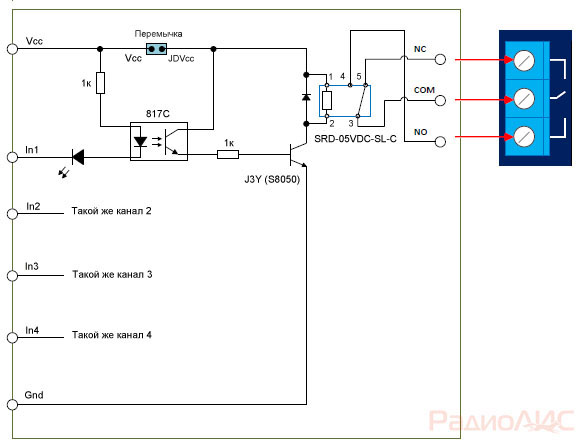
Schematic diagram of the module.
To protect the Arduino outputs from voltage surges in the relay coil, a J3Y transistor and an 817C optocoupler are used. Pay attention, the signal from the pin In applied to the cathode of the optocoupler. This means that in order for the relay to close the contacts, you need to apply to the pinIn logical 0 (inverted signal).
There are also modules that have a signal from the pin In applied to the anode of the optocoupler. In this case, you need to submit logic 1 per pinIn, to operate the relay.
The load power that the modules can turn on / off is limited by the relays installed on the board.
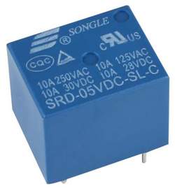
In this case, electromechanical relays are used. Songle SRD-05VDC-SL-C, which has the following characteristics:
Operating voltage: 5 V
Coil working current: 71 mA
Maximum switching current: 10A
Maximum switched DC voltage: 28 V
Maximum switched AC voltage: 250 V
Operating temperature:-25 to +70°C

The Songle SRD-05VDC-SL-C relay has 5 pins. 1 And 2 relay power. Contact group 3 And 4 are normally open contacts ( NO), contact group 3 And 5 - normally closed NC).
Similar relays come in various voltages: 3, 5, 6, 9, 12, 24, 48 V. In this case, a 5-volt version is used, which allows you to power the relay module directly from the Arduino.
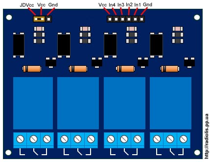
The board has a jumper ( JDVcc), to power the relay either from the Arduino or from a separate power supply.
Pinami In1,In2,In3,In4 the module is connected to the digital pins of the Arduino.
Connecting the relay module HL-54S V1.0 to Arduino.

Since we have a module with 5-volt relays, we will connect it according to this scheme, we will take power from the Arduino itself. In the example, I will connect one relay, I will use a 220 V light bulb as a load.
To power the relay module from the Arduino, the jumper must close the pins " Vcc" And " JDVcc”, usually by default it is installed there.
If your relay is not 5 volts, you cannot power the module from Arduino, you need to take power from a separate source.
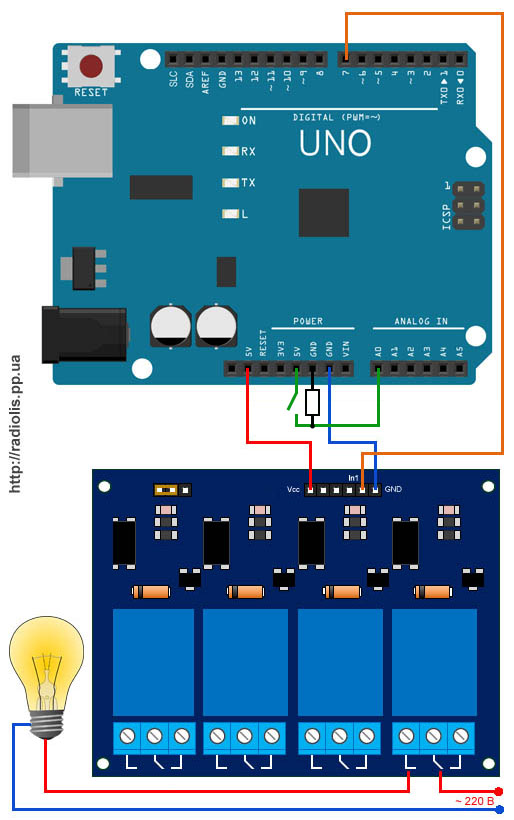
The diagram below shows how to power the module from a separate source. According to this scheme, you need to connect a relay designed to be powered by more or less than 5 V. For 5-volt relays, this scheme will also be more preferable.
With this connection, you need to remove the jumper between the pins " Vcc" And " JDVcc". Next pin " JDVcc» connect to « + » external power supply, pin « Gnd» connect to « - » power supply. Pin " Gnd", which in the previous circuit was connected to the pin" Gnd»Arduino is not connected in this circuit. In my example, the external power supply is 5 V, if your relay is designed for a different voltage (3, 12, 24 V), select the appropriate external power supply.
Sketch for controlling a relay module via Arduino.
Let's upload a sketch to Arduino, which will turn on and off the light bulb (flashing light) itself.
| int relayPin = 7; void setup()( void loop() ( |
In line int relayPin = 7; specify the number of digital pin Arduinoto which the pin was connected In1
module relay. You can connect to any digital pin and specify it in this line.
In line delay(5000); you can change the value of the time at which the light will be on and at which it will be extinguished.
In line digitalWrite(relayPin, LOW); specified, when applying a logical zero ( LOW), the relay module will close the contacts and the light will be on.
In line digitalWrite(relayPin, HIGH); specified, when applying a logical unit ( HIGH), the relay module will open the contacts and the light will go out.
As you can see, in the line digitalWrite(relayPin, LOW); left parameter LOW. If the relay closes the contacts and the light turns on, then the pin In1 you need to feed a logical zero, like me. If the light does not light up, upload the sketch in which we will replace the parameter LOW on the HIGH.
The result of the sketch on the video.
Now let's add a clock button to the circuit and when you click on it, the relay module will turn on the light bulb.

We connect the button together with a 10k pull-up resistor, which will not allow external pickups to affect the operation of the circuit.
Uploading the sketch
In line if(digitalRead(14)==HIGH) set the number of the digital pin on which the button is connected. You can connect to any free. In the example, this analog pinA0, it can also be used as a digital 14 pin.
In line delay(300); the value is given in milliseconds. This value specifies how long after pressing or releasing the button, actions should be performed. This is protection against contact bounce.
For information! All analog inputsfrom A0 ( numbered as 14) to A5 (19), can be used as digital ( digital PWM).
In conclusion, the result of the sketch on the video.
Cheaper relay modules may not contain an optocoupler in their circuit, as, for example, in my case with a single-channel module.
Scheme of a single-channel relay module. The manufacturer saved on an optocoupler, which is why the Arduino board lost its galvanic isolation. For the operation of such a board, on pin In must be a logical zero.
Connecting the module relay to the Arduino Due.
The Arduino Due runs on 3.3 volts, which is the maximum voltage it can have on its inputs/outputs. If there is a higher voltage, the board may burn out.
The question arises, how to connect a module to the relay?

Remove the JDVcc jumper. Connect pin " Vcc» on the relay board of the module to pin "3.3V» Arduino. If the relay is rated for 5 volts, connect the pin " GND» module relay board, with pin « GND» Arduino Due. Pin " JDVcc» connect to pin « 5V» on the Arduino Due board. If the relay is designed for a different voltage, then we connect the power to the relay as in the figure, in the example it is 5 volts. If you have a multi-channel relay module, please check that « JDVcc » connected to one side of all relays. The optocoupler is activated by a 3.3V signal, which in turn activates the transistor used to turn on the relay.
Triac solid state relay for switching a powerful load via Arduino