Sumo- one of the most exciting Lego Ev3 robot competition. In this competition, the robot must push the opponent's robot out of the circle while not leaving the circle itself.
At the very beginning of the competition, the robots are placed in the center of the circle, after the stratum the programs are launched and the robots must wait 3 seconds, after which the robots must reach the border of the circle and only then they have the opportunity to attack the enemy. The portal contains schemes of robots for Lego sumo and assembly instructions
Let's describe Sumo algorithm and program for EV3 robot
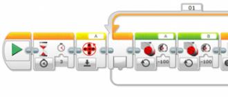
1 Action.
The robot waits 3 seconds, we drive away from the center of the circle to the border, we go forward, we spin, we look for the enemy, we go to the enemy, if we drive from the border, then we drive back.
Set the wait to 3 seconds.
2 Action. We drive back to the border.

3 action. After the robot has driven to the border, it must move forward. Progress.

4 Action. We set up an infinite loop. The robot will attack the enemy until it is pushed out or until the competition time is over.
We put a rotation cycle with an ultrasonic sensor into it. (you can also use an infrared sensor)

5 Action. We go forward until the color sensor sees a black line, the border of the circle.

6. Action After seeing the border, we drive back.
The task.
Write the departure back yourself using lesson 1.
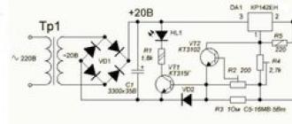
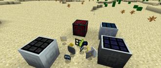
It is the simplest robot, which is made of available materials. With the help of such robots, competitions are held in SUMO, specifically in this homemade product, only one engine is used, there is no printed circuit board, and the body is made of paper.

Video of the robot
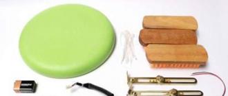
Materials and tools for creating a robot:
- dry glue stick;
- transparent adhesive tape;
- two-output non-fixed button;
- one flashing LED type ARL-513URC-B;
- transistor type KP505A;
- two resistors with a nominal value of 1MΩ and 270Ω;
- clip-connector for connection to the battery type "Krona";
- motor model RF-300CA-D/C 3V or similar.


Functionality and characteristics of the robot:
In the photo you can see the already assembled robot. To move the device, only one motor is used, it is installed vertically, but at a certain angle. When moving on a short segment, the robot moves in a straight line, and on a longer segment it makes an arc.
To turn on the robot, one button is used, when it is pressed, the robot turns on for 20 seconds. After that, an automatic shutdown occurs, and the robot is in standby mode until the next activation.
Another feature of the robot is that it automatically stops at the edge of the ring. The fulfillment of this condition is possible if the weight of the opponent will not be less than the weight of the robot, and the thickness of the ring will not be less than 3 mm.
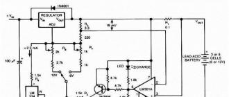
A 9 volt battery is used as a power source, it is installed on top of the robot. Thanks to the extra weight, the robot accumulates the necessary kinetic energy for the necessary actions.

In the picture, the components of the robot are marked with numbers:
1. Clip for battery connection.
2. Battery lock.
3. Power supply (9V battery).
4. Engine.
5. Flashing LED (indicates that power is connected).
6. Button to turn on the robot.
7. Resistor, thanks to it you can set the time of the robot.
8. Capacitor, he is also responsible for the time of the robot.
9. Transistor type KP505A, it is a motor driver.
Robot assembly process:
Step one. We make the case
For the manufacture of the case, the author uses corrugated cardboard, you need to apply a contour on it according to the template. The template can be printed on the printer, it is attached to the article. Further, having made the necessary folds, the template can be cut along thick lines. To install the engine, you need to cut a semicircle in the cardboard, and then bend it a little, as shown in the photo.


Step two. Installation of radioelements
The next step is to install all the necessary radio elements. To do this, you need to take an awl and make holes in the cardboard, they need to be made in round marks. To secure the components, after installation, their leads need to be bent slightly. You can also see a mark in the form of a sight on the cardboard, here you need to make a large hole, a power wire will pass through it.
After that, you can take a soldering iron and start connecting the contacts of the radio elements in accordance with the diagram.


Step three. Fasten the bottom side surfaces
At this stage, you can connect the lower side surfaces. To do this, you need to bend the lower planes and then fix them with transparent tape. Even in the picture you can see the elements of the case turned upwards, they are needed to fix the battery.


Step four. We connect peripherals
To connect power to the battery, you need to use a clip-connector. The wire must be passed through the hole, the red one is soldered to the positive contact of the LED, and the black one to the minus of the capacitor C1.
Then you need to connect the left and right side surfaces, the result should be the letter "P". For reliable fixation of the elements, a staple from the stapler is used. Where to install the brackets is indicated by a white arrow. You can clamp the staples with pliers.


Step five. Installing and connecting the engine
For the robot to move straight, its shaft must be at a certain angle to the surface. In other words, the robot will stand on the side parts, and its shaft will only be in contact with the surface. In order for the robot shaft to have a good grip, you need to put on an elastic band on it, it can be a cambric or a rubber retainer from a helium pen.
The motor is mounted on glue, the lubrication point is marked with a white arrow. After applying the glue, you need to wait a little for it to become viscous, otherwise the liquid glue can get into the engine and ruin it.
For additional fixation, the motor is wrapped with tape.


As for the angle of inclination of the robot, this is all perfectly visible in the pictures. After installation, the motor must be connected. One output is connected to the negative, and the other to the drain of the transistor VT1.
Hey Geektimes!
Introduction
We have long known that robots are our future. There are many branches of robotics. Military development, social, entertainment and just working robots.But this time I want to tell on behalf of the College team at MIREA about the competitive component, but exactly about sumo robots.
A little about our team
We have been in existence since 2014. Winners and prize-winners of most competitions Robofinist, Robofest, the MIPT Spartakiad and smaller tournaments, and we are also the absolute champions of Russia for 2016-2017 in the mini-sumo nomination.Who are these sumo robots anyway?
Initially, when we first learned about such competitions, sumo wrestlers were made mainly from Lego. But this is a pretty bad idea, more on that later.At the moment, the correct sumo wrestler is described very simply: a completely autonomous piece of iron on wheels, with brains and a pair of sensors, which knocks a similar piece of iron out of the ring.
There are 4 types:
1. Mega sumo wrestler
2. Mini sumo wrestler
3. Micro sumo wrestler
4. Nano sumo wrestler
Everyone is different not only externally, but also internally.
Mega - the largest and most dangerous robots. The maximum weight is up to 3 kg, the ability to put various "suckers", which is not allowed to do with other robots.
Mini - pleasant, small robots up to 500 grams 10 by 10 cm. Not difficult to solder, easy to set up and assemble. They are the most popular nomination in sumo.
Micro and nano - reduced mini copies. Micro 5x5x5, nano 2.5x2.5x2.5. Difficult to solder and pick up parts. More popular than mega sumo.
What are they made of?
Let's get back to Lego. Most likely, many of you have tried to do something with a programmable Lego constructor, or at least have seen how it is done. There is even a separate nomination for such robots 15 by 15, but it is terribly boring and suitable only for very beginners or small roboticists. Compared to homemade samples, this one loses in everything except the complexity of assembly.First, it's low speed. Secondly, the size is huge. Thirdly, the low response speed of the sensors. And also the controller itself leaves much to be desired.
More about assembly and packaging
Sumo wrestlers who compete are doing on arduino. They use textolite boards, soldering sensors, a controller, a driver, etc. to it. There is also a wide selection of sensors for detecting an enemy, but it is worth using infrared or laser ones, because sonars are very slow and bulky. Of course, engines and wheels are needed for the robot to move around. You can put them in an unlimited number, but practice shows that the robot rides best on two wheels placed at the back. And, of course, the robot cannot live without a bucket and a hook. The bucket is just a case, a wrapper and protection for the board and elements. Most often steel or iron. The hooks are made from blades for stationery knives, but there are instances with a non-standard approach, for example, a sharpened wooden ruler or cotton wool, but this approach is of little use.The most difficult thing (besides programming) is to design a robot.
First step

This is what is called the very first stage - the placement of engines and sensors. You can also observe here two small sensors in front of the hook, so these are the line sensors.
They are used to detect a white line on the range to avoid accidental falls out of the ring, but are not a required component and are not actually used very often. High speeds often do not allow time to stop.
Second phase

And here the controller, driver, switches and battery connector are already applied.
All that remains is to print the trace and transfer it to a textolite board, and then work out the tracks.
Here's what it looks like on the finished board:
Finished board

Robot ready to run:

As you can see, there is nothing particularly complicated here. About the problems below.
Let's move on to programming
The easiest way is to use arduino or arduino-compatible controllers. Also, Arduino IDE to help us. According to the standard scheme, the robot has 5 sensors. So the states can beWe exclude the situation when the side sensors see the enemy at the same time (because this cannot happen, and if it does, then there is a malfunction in one of the sensors), as well as the situation in which the side and two front sensors give 0 (i.e. . see), because this also cannot be, or the chance is too small.
To make it go to the enemy, we just need to install the pins, apply voltage to the motors and read the sensor readings:
Robot code
// Setting pins for sensors int pin_left=10; int pin_center_left=11; int pin_center_right=4; int pin_center=12; int pin_right=7; // Pins to motors int pin_motor_left_forward=9; int pin_motor_left_back=6; int pin_motor_right_forward=3; int pin_motor_right_back=5; // Variables for storing the result of polling sensors int cl,cc,cr,l,r; // Function for polling sensors void GLAZ() ( cl = digitalRead(pin_center_left); cc = digitalRead(pin_center); cr = digitalRead(pin_center_right); l = digitalRead(pin_left); r = digitalRead(pin_right); ) // Function movement, accepting speeds from 0 to 255 to feed each motor void MOVE(int a, int b) ( if(a<0)
{
digitalWrite(pin_motor_left_forward,LOW);
analogWrite(pin_motor_left_back,0-a);
}
else
{
analogWrite(pin_motor_left_forward,a);
digitalWrite(pin_motor_left_back,LOW);
}
if(b<0)
{
digitalWrite(pin_motor_right_forward,LOW);
analogWrite(pin_motor_right_back,0-b);
}
else
{
digitalWrite(pin_motor_right_back,LOW);
analogWrite(pin_motor_right_forward,b);
}
}
void setup()
{
pinMode (pin_center,INPUT);//центральный
pinMode (pin_right, INPUT);//правый датчик
pinMode (pin_left,INPUT);//левый датчик
pinMode (pin_center_right, INPUT);//передний правый датчик
pinMode (pin_center_left,INPUT);//передний левый датчик
pinMode (pin_line_left, INPUT);
pinMode (pin_line_right, INPUT);
pinMode (pin_start,INPUT);//старт
pinMode (13,OUTPUT);//старт
digitalWrite(13,HIGH);
pinMode (pin_motor_left_back, OUTPUT);//мотор лево назад
pinMode (pin_motor_right_forward, OUTPUT);//мотор право вперед
pinMode (pin_motor_right_back, OUTPUT);//мотор правый назад
pinMode (pin_motor_left_forward,OUTPUT);//мотор лево вперед
// ожидание сигнала к началу схватки
while(!digitalRead(pin_start))continue;
MOVE(200,200);
}
void loop()
{
GLAZ();
if(l && r)
{
if((cl + cc + cr) < 2 || !cc){
MOVE(255,255);
}
if(cc)
{
if(!cl && cr) MOVE(0-180,180);
if(cl && !cr) MOVE(180,0-180);
}
}
else if(cc + cr + cl == 3)
{
if(!l && r) MOVE(0-200,200);
if(!r && l) MOVE(200,0-200);
}
else if(cc)
{
if(!l && !cl && cr && r) MOVE(0-150,150);
if(l && cl && !cr && !r) MOVE(150,0-150);
}
if(!digitalRead(pin_start))while(1){MOVE(0,0);}
}
You just have to improve the code.
Important!
Sensors return 1 if they see nothing and 0 if there is an obstacle.
After downloading the code via usb, the robot is ready to compete.
Worth considering
First, there are the elements. The sensors we use (sharp 340) are quite rare or non-existent. Therefore, if possible, then you need to take a lot at once or find an analogue that is suitable in terms of parameters.Secondly, you can not cause any critical damage to the enemy robot or use, for example, magnets to pick up. This slightly limits us in the choice of means for the struggle.
Also, don't forget the wheels. Curves, thin and sliding will not work, you simply will not be able to maneuver and there will not be enough moment of force. Be sure to test the tires.
When working with engines, keep in mind that they will have to work under maximum load and they will burn quite often.
It also makes sense to make removable batteries, because. The robot is discharged quite quickly, and it takes a long time to charge.
List of necessary purchases:
1. Soldering iron, solder, flux (optional)2. Textolite boards (to etch, you need to close all the tracks, then put it all in a solution of hydrogen peroxide + citric acid + salt for several hours, and then tear off the paper, for example, under which the tracks were hidden)
3. Sharp 340 sensors
4. Engines, choose to taste, the more rpm, the better.
It is worth choosing one of these: polulu. (added)
5. Batteries (I advise you to take lithium polymer) + charging station
6. Key (switch button, soldered to the board) and electrical elements (there is in the picture with a trace)
7. Driver
8. Controller, for starters, you can try Polulu A-Star 32u4 micro and upload the arduino bootloader there
9. Metal sheet for the body
10. Drill for holes in the board
11. Launcher and starter module
P.S. If I missed something - write, I will correct it.
Competitions
The next competitions will be held in St. Petersburg, Robofinist, so now we are intensively preparing for them and if you want to take part, then you need to do everything clearly and quickly.But these competitions are not the only ones, there are quite a lot of them in Russia, the largest ones are held in Moscow. About once a month or two, you can experience happiness and compete.
Such competitions abroad are not uncommon and we also want to get there. Here is an approximate map of competitions around the world:

We really hope that robot sumo will only develop in our country and we invite everyone to participate in the creation of our robot. It looks very epic when pieces fly off from some robot.
This is the end of our introductory article and we wish you all success in robotics, we will be glad to see you at the competitions!
In this competition, participants need to prepare an autonomous robot that can most effectively push the opponent robot out of the black line of the ring.
1. Competition conditions
1.1. The competition takes place between two robots. The goal of the competition is to push the opponent robot beyond the black line of the ring.
1.2. If any part of the robot touches the field outside the black line, the robot loses the round (if a podium-shaped field is used, then the loss is counted if any part of the robot touches the surface outside the podium).
1.3. If at the end of the round no robot is pushed out of the circle, then the robot closest to the center of the circle is considered the winner of the round.
1.4. If the winner cannot be determined by the methods described above, the decision on victory or a replay is made by the judge of the competition.
1.5. During the round, team members must not touch the robots.
2. Field
2.1. White circle with a diameter of 1 m with a black border 5 cm thick.
2.2. In the circle, red stripes mark the starting zones of the robots.
2.3. The red dot marks the center of the circle.
2.4. The field can be in the form of a podium with a height of 10-20 mm.
3. Robot
3.1. There are no restrictions on the use of any components on robots, except for those prohibited by existing rules.*
3.2.1. Throughout the competition:
- The size of the robot should not exceed 250x250x250 mm.
- The weight of the robot must not exceed 1 kg.
3.2.2. Before the start of the round, the robot must satisfy the condition: A triangular plate with an angle of 45 degrees, pressed against the surface of the field, and brought from any side of the robot, must touch the robot at a point above 3 cm from the field. The touch point is fixed with any part of the robot, including: wheels, tracks, rubber bands, wires...

3.2.3. Dispute between the participant and the judge on points of rules 3.2. during the check of the robot, is always decided not in favor of the participant.
3.3. The robot must be autonomous.
3.4. A robot that, in the opinion of the judges, deliberately damages or soils other robots, or otherwise damages or contaminates the surface of the field, will be disqualified for the entire duration of the competition.
3.5. Before the match, the robots are checked for dimensions, weight, and the distance of parts from the field.
3.6. Structural restrictions:
- It is forbidden to use any adhesive devices on the wheels and the body of the robot.
- Do not use any lubricants on exposed surfaces of the robot.
- It is forbidden to use any devices that give the robot increased stability, for example, creating a vacuum environment.
- It is forbidden to interfere with the IR and other sensors of the rival robot, as well as interfere with electronic equipment.
- It is forbidden to use devices that throw something at the rival robot.
- It is forbidden to use liquid, powder and gas substances as a weapon against a rival robot.
- It is forbidden to use flammable substances.
- It is forbidden to use structures that can cause physical damage to the ring or the rival robot.
Robots that violate the above prohibitions are removed from the competition.
3.8. Participants have the right to promptly constructive change of the robot between rounds (including repair, replacement of batteries, choice of program, etc.), if the changes made do not contradict the requirements for the design of the robot and do not violate the rules of the competition. The time for the operational constructive change of the robot is controlled by the judge, but cannot exceed 1 minute.
3.9. Between matches, it is allowed to change the design and programs of robots.*
4. Conducting competitions.
4.1. Competitions consist of a series of matches. The match determines the strongest of the two robots participating in it. The match consists of 3 rounds of 30 seconds. Rounds are held in a row.*
4.2. Competitions consist of at least two attempts (the exact number is determined by the organizing committee). An attempt is a collection of all matches in which each robot participates at least 1 time.*
4.3. Before the first attempt and between attempts, teams can adjust their robot.
4.4. Teams must place their robots in a "quarantine" area prior to starting an attempt. After the judge confirms that the robots meet all requirements, the competition can begin.*
4.5. If during the inspection a violation in the design of the robot is found, the judge gives 3 minutes to eliminate the violation. However, if the violation is not corrected within this time, the team will not be able to compete.
4.6. After placing the robot in "quarantine" can not be modified(for example: download a program, change batteries)or change robots until the end of the attempt.*
4.7. Judges and robot operators participate directly in the duel - one from each team.
4.8. After starting the robots, operators must move away from the field by more than 1 meter within 5 seconds.
4.9. Each operator once during the entire match can stop the start of the round without penalty, but no later than 1 second before the end of the 5-second countdown. Start delay is allowed no more than 30 seconds. A delay for a longer time may be carried out only with the special permission of the judge. After fixing the problem, the robots are set to start again.*
4.10. If during the round any electrical part of the robot is not firmly fixed (torn off or hanging on wires), then this robot is considered the loser in the round.
4.11. If during the match, the design of any robot was unintentionally damaged, and requires more than 50 seconds to repair, then the match may be interrupted and the team is allowed to fix the design of the robot, at this time matches with other teams can take place, after repairing the robot and completing the current match, the interrupted match continues.*
4.12. The match is won by the robot that wins the most rounds. The judge may use an additional round to clarify disputed situations.
4.13. The round is played by the robot if:
- One of the parts of the robot touched the area beyond the black border of the ring.
- If the robot is further from the center of the ring than the opponent's robot. If the time of the round has expired and not one of the robots has gone beyond the boundaries of the ring.
5. Competition Options
5.1. The rules provide for three levels of difficulty. The organizer of the competition is obliged to warn the participants in advance about the chosen level of difficulty.
5.2. Level #1: No maneuvers. For beginners. It is solved mainly mechanically.
5.2.1. After the judge announces the start of the round, the robots are placed by the operators in front of the red lines.
5.2.2. When the robots are set to their starting positions, the judge asks about the readiness of the operators, if both operators are ready to start the robot, then the judge gives a signal to start the robots.
5.2.2. After the signal to start the robots, the operators start the program.
5.2.3. Robots must drive in a straight line and collide with each other.
5.2.4. Robots are not allowed to intentionally maneuver around the ring.
5.3. Level #2: Limited maneuverability. Requires experience. Provides the ability to maneuver across the field.
5.3.1. After the judge announces the start of the round, the robots are placed by the operators in front of the red lines.
5.3.2. When the robots are set to their starting positions, the judge asks about the readiness of the operators, if both operators are ready to start the robot, then the judge gives a signal to start the robots.
5.3.3. After the signal to start the robots, the operators start the program.
5.3.4. The robots must drive straight and collide with each other, after the collision, the robots can maneuver around the ring as they please. The time from the beginning of the round to the collision of robots should not exceed 5 seconds.
5.3.5. If the robots do not collide within 5 seconds after the start of the round, then the robot due to which, in the opinion of the judge, there is no collision, is considered the loser of the round.
5.3.6. If the robots go straight and do not have time to collide in 5 seconds, then the robot located further from the center of the field is considered the loser of the round.
5.4. Level #3: Increased maneuverability. Requires good skills. Forces the robot to navigate in space.
5.4.1. The robot, in its design, must have a clearly visible start button that performs the function of turning the robot on and off.
5.4.2. After the judge announces the start of the round, the robots are prepared by the operators, after preparation, the operator must inform the judge that the robot is ready, after that, until the end of the round, the operator cannot enter any data into the robot, and the robot program must be launched by pressing the start button.
5.4.3. After the robots are ready, the judge determines the arrangement of the robots at the beginning of the round by drawing lots.
Examples of robot placement:


5.4.4. The judge puts the robots on the starting positions.*
5.4.5. At the command of the judge, by pressing the start button, the operators start the robots.
6. Refereeing
6.1. The organizing committee reserves the right to make any changes to the competition rules if these changes do not give advantages to one of the teams.
6.2. Control and summing up is carried out by the panel of judges in accordance with the above rules.
6.3. Judges have full powers throughout all competitions; all participants must abide by their decisions.
6.4. The judge may use additional rounds to clarify disputes.
6.5. If there are any objections regarding refereeing, the team has the right to orally appeal the decision of the referees to the Organizing Committee no later than the end of the current match.
6.6. The replay of the round can be carried out by the decision of the judges in the event that there was an outside interference in the work of the robot, or when the malfunction occurred due to the poor condition of the playing field, or due to an error made by the panel of judges.
6.7. Team members and the leader must not interfere with the actions of the robot of their team or the robot of the opponent, either physically or from a distance. Interference leads to immediate disqualification.
7. Winner Selection Rules
7.1. According to the decision of the organizing committee, the ranking of robots can take place according to different systems, depending on the number of participants and the rules of the event within which the competition is held. Recommended system:
o The first attempt, in which all participants participate in the Olympic system (elimination) until 3-5 (number of finalists announced in advance) finalists are determined. Participants are grouped into pairs in turn: the first with the second, the third with the fourth, etc.
o The second attempt, in which all participants participate according to the Olympic system (elimination) until the determination of 3-5 (number of finalists announced in advance) finalists. Participants are grouped into pairs through one: the first with the third, the second with the fourth, etc.
o All finalists of the previous attempts participate in the final and compete according to the system each with each. The ranking is based on the number of matches won. In disputable situations, additional matches are held.
* the noted points of the regulations can be canceled or changed by the organizing committee of a particular stage of the competition.
Tips for the organizing committee:
- At least 2 referees are required for the competition: The first referee conducts the matches, the second one checks the robots before the matches.
- If the ring is made in the form of a round platform, then the competition will be more spectacular and it will be easier for the judges to determine the robot that has fallen out of the ring.
Order of conduct.
Competitions consist of a series of matches. The match determines which of the two robots participating in it is the strongest. Depending on the number of participants, the match consists of 3 or 5 rounds of 30 seconds. The match is won by the robot that wins the most rounds. The judge may use an additional round to clarify disputed situations.
By decision of the organizing committee, the ranking of robots can take place according to different systems, depending on the number of participants and the rules of the event within which the competition is held.
- 6-26 participants - 5 rounds per match, 20-40 participants - 3 rounds per match.
- The first attempt in which all participants participate in the Olympic system (eliminating) until the determination of 3-5 (the number of finalists is announced in advance) finalists. Participants are grouped into pairs in turn: the first with the second, the third with the fourth, etc.
- The second attempt in which all participants participate in the Olympic system (elimination) until the definition of 3-5 (the number of finalists is announced in advance) finalists. Participants are grouped into pairs through one: the first with the third, the second with the fourth, etc.
- All the finalists of the previous attempts participate in the final and compete according to the system, each with each. The ranking is based on the number of matches won, but at the beginning of the final, all finalists are considered equal. In disputable situations, additional matches are held.
- 3 rounds in a match. Breaks between attempts 30 min.
- First, the participants are divided into 4 equal groups. In the first attempt, groups 1 and 2 participate in the first field, and groups 3 and 4 participate in the second field. Each participant plays on his field according to the "each with each" system. This ensures 50% of the meetings of each team with opponents.
- In the second attempt, groups 1 and 3 participate on the first field, and groups 2 and 4 participate on the second field. Each participant wins back on his field according to the "each with each" system, without repeated meetings held in the last attempt. This ensures 75% of the meetings of each team with opponents.
- The third attempt is carried out with sufficient time and is not mandatory. In the third attempt, groups 1 and 4 participate on the first field, and groups 2 and 3 participate on the second field. Each participant wins back on his field according to the "each with each" system, without repeated meetings held in previous attempts. This ensures 100% of the meetings of each team with opponents.
- 5-7 teams that win the most matches participate in the final. Finalists compete according to the system each with each. The ranking is based on the number of matches won, but at the beginning of the final, all finalists are considered equal. In disputable situations, additional matches are held.
Note: keep in mind that the Olympic ranking system may unfairly evaluate participants if equal opponents meet in pairs. In this regard, we advise you to rank "each with each" among as many participants as possible. one
- Operators can set up the robot at any time except for their match and up to 5 minutes before it.
- If during the inspection a violation is found in the design of the robot, the judge will give 3 minutes to eliminate the violation. However, if the violation is not corrected within this time, the team will not be able to participate in the competition.
- Teams cannot request extra time before a match.
- Before the start of the round, operators can choose a program and must place the robots in the strat zone (behind the red line). Further, the judge confirms the readiness of the participants and gives a signal to start the round, while the robot operators must run the program on the robots and move away from the field by more than 1 meter within 5 seconds. In the same 5 seconds, the robots must travel in a straight line and collide with each other. After the collision, the robots can maneuver around the ring as they please.
- During a match, one of the judges calls a couple of contestants to the next round and checks their robots.
- Before the start, the robot must be completely in the stratum zone (behind the line).
Competition time calculation:
Approximate match time in 5 rounds:
~ calling a team and checking robots (3 min) + 5 * (setting robots (10 sec) + round (30 sec) = 3-4 min.
Competition time T when playing each with each for N teams:
T=((N*N-1)/2)*4 min
Example with 10 commands:
((10*9)/2)*4 min = 3 hours.
An example with 10 teams in a mixed (each with each + Olympic) system:
((5)+(5*4)/2)*4 min = 1 hour.
Indicative Schedule for a two-run competition with 20 teams:
- 9:00 – 9:30 Registration of teams.
- 9:30 – 9:45 Meeting with the participants (Clarification of the rules).
- 9:45 – 10:30 Robot preparation.
- 10:30 – 11:30 Holding 1 attempt at competitions according to the Olympic system ((10+5)*4min=1hour)
- 11:30 – 12:00 Break.
- 12:00 – 13:00 Conducting 2 attempts at competitions according to the Olympic system ((10 + 5) * 4min = 1 hour)
- 13:00 – 14:00 Break. (Holding additional matches if many teams are in the top five in the first attempts)
- 14:00 – 15:00 Final. Everyone with everyone.
- 15:00 – 16:00 Summing up.
- 16:00 – 17:00 Rewarding.
PROGRAM "MINI-SUMO ROBOT. The final article on assembling a mini-sumo robot. In the first part of the article "Chassis for a mini-sumo robot" it was described in detail how to make a robot chassis. In this article, we will analyze in detail the compilation of a program for a robot. Our robot ready. It has a chassis, the function of "brains" will be performed by a microcontroller, and communication with the outside world will be carried out by sensors. But, despite all this, it will still stand motionless on the table. And to prevent this from happening, it's time to breathe into our creation life, so to speak, to feel like a "creator" completely.The program that we will create will not only revive the robot, but also make it behave meaningfully and logically in the ring.
1. The basis of the program is the algorithm.
As before, we cannot do without a plan. In the previous article, our plan was a circuit diagram. In programming, a plan is called an algorithm. Some of you know what it is, someone just heard, but there are those who did not know and hear for the first time.
I will not use scientific terms, I will simply say that an Algorithm is a description of a sequence of certain actions. Our whole life is various actions; we walk, we talk, we move our arms and legs, we turn our heads. All this has its own meaning - an algorithm, a sequence that determines our behavior, and it can be compiled and described. For clarity, I will give an example from life. You brush your teeth every morning. Try to describe how you do it, how to write a program for yourself. Here's what happens: “We take a toothbrush. Squeeze out the paste. We brush our teeth with left-right movements. I rinse my mouth. My brush."
In principle, everything is correct, but we can perform this small program at lunchtime, in the evening, or after every meal. But we did not take into account important factors that can nullify all our efforts. Initially, we talked about the morning. This is an important factor, and if you do not take it into account, then you will have to brush your teeth while lying in bed and with your eyes closed. Therefore, any program must always have some kind of beginning and end with the possibility of repeating the cycle. The repeating cycle for a person is the next day, where it will be morning again, and teeth will need to be brushed again. Therefore, we add the following algorithm (sequence of actions) to our program.
"Wake up. Get out of bed...” If you stop creating the algorithm at this stage and go straight to brushing your teeth, the program will stall (hang). Why? Because we again did not take into account all the factors. You are standing in the middle of your bedroom and unable to execute the next command; “We take a toothbrush”, since the brush is in the bathroom, and you still need to get into it. Well, if you sleep in the bathroom, then no problem - the program will run! But in most cases, normal people sleep in another room. This approach is called logical, that is meaningful. All our actions must be reasonable and contain a certain meaning, otherwise the goal will not be achieved. So "Wake up. Get up. Go to the bathroom" would be the best option.
Let's get back to work. Now how do we plan the actions of the mini-sumo robot in the ring? We have rules where the goal is clearly marked - "Push the opponent out of the ring." But to achieve it, certain factors must be taken into account. The main factor is not to go beyond the circle itself, or to be more precise, not to go beyond the white border of the circle. Here's what we got:
Rice. 1 Algorithm of the robot's behavior in the ring.
In Figure 1 you see a block diagram. By all rights, this is how it is customary to compose algorithms. Clear and understandable.
The first block is "Start". From this moment, the program starts executing the actions of the robot after it is turned on. The first thing he will have to do is to find the enemy, the "Target Search" block. The next block of our scheme is in the form of a rhombus “Target found?”. This means that we will have a choice of actions to achieve a certain event. If the target is found (Yes), then we will continue the execution of the program and move on to the next part of the “Attack” program, but if the target is not found (No), then it is most logical to continue searching for it. The program will loop on this moment until the robot detects the enemy. When attacking, the robot moves forward towards the opponent, trying to push him out of the ring, at this moment the “Did you reach the edge of the ring?” proceeds to the next block "Drive back" and "Reversal". After the turn, the cycle of the main program is repeated, that is, it starts from the very beginning and the robot is again looking for the enemy. It was done so for a reason. If at the time of the attack, the enemy managed to escape from our robot, then we must return to his search without leaving the edge of the ring. Everything with theory. Let's move on to practice.
2. Rules for writing programs for Arduino.
Although I said that the theoretical part is over, we should study the principle of building a program for Arduino microcontrollers, although these principles will be true for other MKs of the AVR family.

Rice. 2 Method of writing a program for Arduino.
This flowchart clearly shows us what important points, and in what order, should be observed when writing a program.
At the very beginning of the program, if necessary, additional modules are connected. Then the global variables are declared. Next comes the controller initialization block. It defines the port assignments, whether it is an input or an output, and other settings. Additional auxiliary routines can also be called from this block. To be brief, in this place the program makes preliminary settings for the controller. This block is executed once when starting or rebooting the controller. Please note that the line "delay 5 seconds" has been added to the block. This does not apply to the general rules for writing a program, but it is necessary for a mini-sumo robot. The rules say that after the referee's command, the robots must start moving after 5 seconds. This delay cannot be performed in the main loop of the program, as it will be constantly repeated, and the behavior of the robot will not change for the better.
In the block of the main cycle of the program, the main algorithm of the robot's behavior in the ring will be executed, which we have considered in Fig. 1. During the operation of the main loop, it will be possible to access subroutines. Programmers very often use subroutines to optimize and reduce code. For example, it is more logical to single out a program for moving forward or backward into separate modules and not include it in the main body of the program. From this it will become huge, completely unreadable, and it will be very problematic to find an error or make a small change.
3. Arduino IDE development tool.
Download the latest Arduino IDE from Arduino.ru. The program does not require any special installation, it is enough to unpack the contents of the archive to the right place. At the end of this article is the Ultrasonic rangefinder library file. It should be unpacked into the Libraries folder.
We launch the application. We check the correct installation of the library, go to the menu, "File" - "Examples". Almost at the very bottom, the Ultrasonic item should appear as in fig. 3.

Rice. 3 Verify that the Ultrasonic library is installed correctly.
If everything is fine, go to the "Service" - "Pay" item. We need to choose our board - Arduino Pro Mini 5v.

Rice. 4 controller board setup
The serial port must be selected the one that appears after connecting the Arduino to the computer. A little should be said about the Arduino Pro Mini. Unlike other controllers in the Arduino family, the Pro Mini does not have a built-in computer connection module. It is supplied separately as a USB to UART(TTL) adapter board and is connected to the controller board using four wires.

Rice. 5 USB-UART (TTL) adapter.
On fig. 6 shows how to properly connect the controller and adapter.

Rice. 6. Connecting the controller to the USB-UART adapter.
Unlike the received connection of signal lines, instead of RX-TX and TX-RX, these lines need to be connected directly: RX-RX, TX-TX. The first time you connect the adapter to your computer, the device drivers will automatically start installing. You should wait for the installation to finish. Another feature of the controller is the absence of a software reset Reset at the time of programming. This is of course a little inconvenient, but not enough to refuse the Pro Mini. It is enough to press the Reset button on the controller after the inscription "Compiling" changes to "Download", Fig. 7.

Rice. 7. Displaying information about the progress of programming MK.
4. We write the code.
In this chapter, I will not dwell on the description of commands, directives and operators. It is assumed that you already have some basic knowledge. Otherwise, you need to refer to the documentation on the official website or other sources on the network. We will write the program code clearly according to the plan or algorithm that we have compiled. I added code to certain blocks of the algorithm, which we will now consider in more detail in Fig. 8.

Rice. 8. Writing the initial block of the program.
The first block: the directive # connects the module control library to our project.
Second block: We declare variables and write initial values equal to zero into them. Please note that we will not create names for the output ports of the MK. I deliberately left them in digital form so that you can easily refer to the circuit diagram. In this block, we declare only three variables - these are the left and right sensors of the ring (_ and _), they will store the ADC values. As well as the distance variable of the ultrasonic rangefinder (_), it will record the distance in centimeters to the obstacle.
The line Ultrasonic ultrasonic (4, 2) is nothing more than a declaration of a variable for the ultrasonic rangefinder, taken from the example of the included library. In parentheses are the ports to which the sensor legs and are connected.
The third block: (), in it we configure all the inputs and outputs of the microcontroller. We will receive incoming signals on ports 15, 17, so we assign (Input) to them. We have four ports controlling the engines: 3.5 for the left engine and 6.9 for the right engine, we assign them as an output.
Why do we use two ports for one engine? Everything is simple; If voltage is applied to the motor contacts, it will begin to spin in one of the directions, say clockwise. But if you change the polarity, i.e. change the "plus" and "minus" - the motor shaft will spin in the other direction. We will use this property for full-fledged maneuvers.
5. The main loop loop.
In this cycle, the main program of the controller is executed. You can't get out of it completely or complete it. From it, only calls to external procedures, the so-called subroutines, are possible.
Consider the structure of our cycle based on the algorithm in Fig. nine

Rice. 9. Algorithm of the main loop Loop.
From the very beginning, we need to get the readings of all sensors, for this we call the subroutine:
void check_sensor() // Subroutine for checking sensors.
R_Sensor=analogRead(15); // read the right sensor readings
L_Sensor=analogRead(17); // read the readings of the left sensor
delay(10); //delay to finish ADC conversion
dist_cm = ultrasonic.Ranging(CM); // read the readings of the ultrasonic rangefinder
delay(10); // Delay to finish conversion
After receiving the data, we need to process it. First we must determine our location, whether we are in the ring or not. If we check the presence of an opponent within 40 cm in the ring. If there is no opponent, we are looking for him by turning to the left procedure:
void go_left() // search for a target or go left
analogWrite(5, 100); //LEFT MOTOR
analogWrite(6, 100); //RIGHT MOTOR
The value of the power of the motors is almost halved, if we spin too fast, we can slip through the detected target by inertia.
If the target is detected, we must attack it, moving forward at full speed.
void go_forward() //Attack - moving forward
analogWrite(3, 0); //LEFT MOTOR
If at the time of the attack we ran into the edge of the ring and found a white stripe, then we need to stop, back out, turn around and drive a little forward, then resume the search again. To do this, call the procedures in order:
go_stop(); // stop
delay(100); //wait 10ms
go_back(); // Move back
delay(1000); //1 second.
go_right(); //Turn right
delay(300); //300ms
go_forward(); //Move forward
delay(300); //300ms
void go_stop() //stop
analogWrite(5, 255); //LEFT MOTOR
analogWrite(9, 255); //RIGHT MOTOR
void go_back () //go back
analogWrite(3, 255); //LEFT MOTOR
analogWrite(6, 255); //RIGHT MOTOR
analogWrite(9, 0); //RIGHT MOTOR
void go_right () //search for a target or move to the right
analogWrite(3, 100); //LEFT MOTOR
analogWrite(5, 0); //LEFT MOTOR
analogWrite(6, 0); //RIGHT MOTOR
analogWrite(9, 100); //RIGHT MOTOR
void go_forward() //Attack forward movement
analogWrite(3, 0); //LEFT MOTOR
analogWrite(5, 255); //LEFT MOTOR
analogWrite(6, 0); //RIGHT MOTOR
analogWrite(9, 255); //RIGHT MOTOR
Time delays between procedures determine the duration of the engines in different directions of movement. If you increase or decrease it, then you can achieve different angles of rotation or the distance that the robot will travel before the next command is executed.
The full sketch for download is at the end of the article.
The presented code, of course, is not the final or most correct option, each of you has the right to supplement or correct it to suit your requirements, because the general essence of the article is to teach beginner roboticists to think logically and systematically, to solve the tasks correctly using all available resources.
Archive 1
Archive 2 to the article "Program of the minisumo robot".
If YOU have any questions, write on the FORUM or in the Online chat on robotics, we will discuss them!
Attention! Full or partial copying of material without the permission of the administration is prohibited!
Hey! Would you like to assemble a robot that is not difficult to assemble? You've come to the right place! =) It is on our site that you can find detailed articles on step-by-step assembly of your first robot, as well as many other robots, and even for competitions.
We are very glad that our articles will help you, a beginner in robotics, to master this most interesting area and pump your skills in this direction. We also want to note that according to these articles, we, the developers of the SERVODROID website, conduct classes in free circles of robotics, and we really like to teach and tell everyone what BEAM robotics is.
Help our project! Register on our website and come to our Online chat or forum and share your crafts and your progress - after all, it is your activity that attracts more and more attention to robotics for beginners - they look at your success and want to become just as cool, and we really It's nice to see that everything works out for you. And if something doesn't work out - we will help;)