The circuit design of these power supplies is approximately the same for almost all manufacturers. A small difference applies only to AT and ATX power supplies. The main difference between them is that the AT power supply does not support the advanced power management standard in software. You can turn off this power supply only by stopping the supply of voltage to its input, and in ATX power supplies it is possible to programmatically turn it off using a control signal from the motherboard. As a rule, an ATX board is larger than an AT board and is elongated vertically. 
In any computer power supply, the +12 V voltage is intended to power the disk drive motors. The power supply for this circuit must provide a large output current, especially in computers with many drive bays. This voltage is also supplied to the fans. They consume current up to 0.3A, but in new computers this value is below 0.1A. +5 volt power is supplied to all components of the computer, therefore it has very high power and current, up to 20A, and the +3.3 volt voltage is intended exclusively for powering the processor. Knowing that modern multi-core processors have a power of up to 150 watts, it is not difficult to calculate the current of this circuit: 100 watts/3.3 volts = 30A! Negative voltages -5 and -12V are ten times weaker than the main positive ones, so there are simple 2-amp diodes without radiators.
The tasks of the power supply also include suspending the functioning of the system until the input voltage reaches a value sufficient for normal operation. Each power supply undergoes internal checks and output voltage testing before being allowed to start the system. After this, a special Power Good signal is sent to the motherboard. If this signal is not received, the computer will not work

The Power Good signal can be used for manual reset if applied to the clock generator chip. When the Power Good signal circuit is grounded, clock generation stops and the processor stops. After opening the switch, a short-term processor initialization signal is generated and normal signal flow is allowed - a hardware reboot of the computer is performed. In computer power supplies of the ATX type, there is a signal called PS ON; it can be used by the program to turn off the power source.To check the functionality of the power supply, you should load the power supply with lamps for car headlights and measure all output voltages with a tester. If the voltage is within normal limits. It is also worth checking the change in the voltage supplied by the power supply with a change in load.
The operation of these power supplies is very stable and reliable, but in the event of combustion, powerful transistors, low-resistance resistors, rectifier diodes on the radiator, varistors, transformer and fuse most often fail.


For our purposes, absolutely any computer power supply will be suitable. At least 250 watts, at least 500. The current that it will provide is enough for an amateur radio power supply.

The modification of an ATX computer power supply is minimal and can be repeated even by novice radio amateurs. The main thing is to remember that the ATX switching computer power supply has many elements on the board that are under 220V mains voltage, so be extremely careful when testing and configuring!The changes affected mainly the output part of the ATX power supply.


The fact is that the computer power supply contains not only the main powerful 300-watt converter with +5 and +-12V buses, but also a small auxiliary power supply for the standby mode of the motherboard. Moreover, this small switching power supply is completely independent from the main one.

It is so independent that it can be safely cut out from the main board and, by selecting a suitable box, used to power some electronic devices.The modification affected only the wiring of the microcircuitTL431, first assembled the divider,but then he acted more simply - an ordinary trimmer. With it, the adjustment limit is from 3.6 to 5.5 volts.


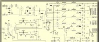
Here is a typical diagram of an ATX computer power supply, and below is a diagram of the section of the auxiliary standby converter.


Naturally in each specific power supply ATXthe scheme will be different. But I think the principle is clear.
We carefully cut out the required section of the printed circuit board with a ferrite transformer, transistor and other necessary parts and connect it to a 220V network and test the functionality of this unit.


In this case, the output voltage was set to exactly 4 volts, the protection response current was 500 mA, since this UPS is used to test mobile phones.

The power of the resulting UPS is not great, but it is definitely higher than standard pulse charges from mobile phones. Absolutely any computer power supply is suitable for this power supply conversion.ATX.
For ease of use, this laboratory power supply can be equipped with a digital indication of current and voltage. This can be done either on a microcontroller or on a specialized chip.


provides the following parameters and functions:
1. Measurement and indication of the output voltage of the power supply in the range from 0 to 100V, with a resolution of 0.01V
2. Measurement and indication of the output load current of the power supply in the range from 0 to 10A with a resolution of 10 mA
3. Measurement error - no worse than ±0.01V (voltage) or ±10mA (current)
4. Switching between voltage/current measurement modes is carried out using a button that is locked in the pressed position.
5. Output of measurement results to a large four-digit indicator. In this case, three digits are used to display the value of the measured value, and the fourth is used to indicate the current measurement mode.
6. A special feature of my voltammeter is the automatic selection of the measurement limit. The idea is that voltages 0-10V are displayed with an accuracy of 0.01V, and voltages 10-100V with an accuracy of 0.1V.
7. In reality, the voltage divider is designed with a reserve, if the measured voltage increases more than 110V (well, maybe someone needs less, you can fix this in the firmware), overload symbols are displayed on the indicator - O.L (Over Load). The same is done with the ammeter; when the measured current exceeds 11A, the voltammeter goes into overload indication mode.
The device measures and displays only positive current and voltage values, and a shunt in the negative circuit is used to measure the current.
The device is made on the DD1 microcontroller (MK) ATMega8-16PU.

Technical parameters of ATMEGA8-16PU:
AVR core
Bit size 8
Clock frequency, MHz 16
8K ROM capacity
RAM capacity 1K
Internal ADC, number of channels 23
Internal DAC, number of channels 23
Timer 3 channels
Supply voltage, V 4.5…5.5
Temperature range, C 40...+85
Housing type DIP28
The number of additional circuit elements is minimal. (More complete data on the MK can be found in the datasheet for it).The resistors in the diagram are type MLT-0.125 or imported analogues, an electrolytic capacitor type K50-35 or similar, with a voltage of at least 6.3V, its capacity may differ upward. Capacitor 0.1 µF - imported ceramic. Instead of DA1 7805, you can use any analogues. The maximum supply voltage of the device is determined by the maximum allowable input voltage of this microcircuit. The type of indicators is described below. When processing a printed circuit board, it is possible to use other types of components, including SMD.
Resistor R... imported ceramic, resistance 0.1 Ohm 5W, it is possible to use more powerful resistors if the dimensions of the signet allow installation.You also need to study the power supply current stabilization circuit; perhaps there is already a 0.1 Ohm current-measuring resistor in the negative bus. It will be possible to use this resistor if possible.To power the device, either a separate stabilized +5V power supply can be used (then the microcircuit power stabilizer DA1 is not needed), or an unstabilized source of +7...30V (with the mandatory use of DA1). The current consumed by the device does not exceed 80mA. Please note that the stability of the supply voltage indirectly affects the accuracy of current and voltage measurements.The indication is an ordinary dynamic one, at a certain moment in time only one digit is lit, but due to the inertia of our vision, we see all four indicators glowing and perceive it as a normal number.
I used one current-limiting resistor per indicator and abandoned the need for additional transistor switches, since the maximum current of the MK port in this circuit does not exceed the permissible 40 mA. By changing the program, it is possible to realize the possibility of using indicators with both a common anode and a common cathode.The type of indicators can be any - both domestic and imported. My version uses two-digit VQE-23 green indicators with a digit height of 12 mm (these are ancient, low-brightness indicators found in old stocks). Here I will provide its technical data for reference;
Indicator VQE23, 20x25mm, OK, green
Two-digit 7-segment indicator.
Type Common cathode
Color green (565nm)
Brightness 460-1560uCd
Decimal points 2
Rated segment current 20mA
Below is the location of the pins and the dimensional drawing of the indicator:
1. Anode H1
2. Anode G1
3. Anode A1
4. Anode F1
5. Anode B1
6. Anode B2
7. Anode F2
8. Anode A2
9. Anode G2
10. Anode H2
11. Anode C2
12. Anode E2
13. Anode D2
14. Common cathode K2
15. Common cathode K1
16. Anode D1
17. Anode E1
18. Anode C1
It is possible to use any indicators, both one-, two-, and four-digit with a common cathode; you only have to do the wiring of the printed circuit board for them.The board is made of double-sided foil fiberglass,but it is possible to use one-sided, you just need to solder a few jumpers. Elements on the board are installed on both sides, so the order of assembly is important:
First you need to solder the jumpers (vias), of which there are many under the indicators and near the microcontroller.
Then microcontroller DD1. You can use a collet socket for it, but it must not be installed all the way into the board so that you can solder the pins on the side of the microcircuit. Because There was no collet socket under the paw, it was decided to solder the MK tightly into the board. I don’t recommend it for beginners; in case of unsuccessful firmware, it is very inconvenient to replace a 28-legged MK.
Then all the other elements.
The operation of this voltammeter module does not require explanation. It is enough to correctly connect the power and measuring circuits.An open jumper or button – voltage measurement, a closed jumper or button – current measurement.The firmware can be uploaded to the controller in any way available to you. From Fuse bits, what needs to be done is to enable the built-in 4 MHz oscillator. Nothing bad will happen if you don’t flash them, the MK will just work at 1 MHz and the numbers on the indicator will flicker a lot.

I cannot give specific recommendations, other than the above, on how to connect a device to a specific power supply circuit - there are so many of them! I hope this task really turns out to be as easy as I imagine.P.S. This circuit has not been tested in a real power supply; it was assembled as a prototype; in the future it is planned to make a simple adjustable power supply using this voltammeter. I would be grateful to those who test this voltammeter in operation and point out significant and not so significant shortcomings.The basis is the circuit from ARV Modding power supply from the radiocat website. Firmware for the ATmega8 microcontroller with source codes for CodeVision AVR C Compiler 2.04, and the board in ARES Proteus format can be downloaded from here. Also attached is a working draft in ISIS Proteus. Material provided by i8086.
All main and additional parts of the power supply are mounted inside the ATX power supply case. There is enough space there for them, and for a digital voltammeter, and for all the necessary sockets and regulators.

The last advantage is also very important, because enclosures are often a big problem. Personally, I have a lot of devices in my desk drawer that never got their own box.

The body of the resulting power supply can be covered with decorative black self-adhesive film or simply painted. We make the front panel with all the inscriptions and designations in Photoshop, print it on photo paper and paste it onto the body.


Long-term tests of the laboratory power supply have shown its high reliability, stability and excellent technical characteristics. I recommend everyone to repeat this design, especially since the limit is quite simple and the end result will be a beautiful compact power supply.
LABORATORY POWER SUPPLY FROM COMPUTER ATX
Every year, it becomes more and more difficult to get a good transformer for a power supply. So that the voltage and current are required. Recently I needed to assemble an adapter for one device, so it turns out that the prices for ordinary transformers in radio stores are in the range of 5-15 euros! Therefore, when it was necessary to make a good laboratory power supply, with voltage and protection current adjustments, the choice fell on a computer one as the basis of the design. Moreover, its price is now not much more than the price of a conventional transformer.

For our purposes, absolutely any computer power supply will be suitable. At least 250 watts, at least 500. The current that it will provide is enough for an amateur radio power supply.

The modification is minimal and can be repeated even by novice radio amateurs. The main thing is to remember that the ATX switching computer power supply has many elements on the board that are under 220 V mains voltage, so be extremely careful when testing and configuring!The changes affected mainly the output part of the ATX power supply.


For ease of operation, this laboratory power supply can be supplied with current and voltage. This can be done either on a microcontroller or on a specialized chip.


All main and additional parts of the power supply are mounted inside the ATX power supply case. There is enough space there for them, and for a digital voltammeter, and for all the necessary sockets and regulators.

The last advantage is also very important, because enclosures are often a big problem. Personally, I have a lot of devices in my desk drawer that never got their own box.

The body of the resulting power supply can be covered with decorative black self-adhesive film or simply painted. We make the front panel with all the inscriptions and designations in Photoshop, print it on photo paper and paste it onto the body.
In this article I will tell you how to make a laboratory power supply from an old computer power supply that is very useful for any radio amateur.
You can buy a computer power supply very cheaply at a local flea market or beg it from a friend or acquaintance who has upgraded his PC. Before you start working on a power supply, you should remember that high voltage is dangerous to life and you need to follow safety rules and exercise extreme caution.
The power supply we made will have two outputs with a fixed voltage of 5V and 12V and one output with an adjustable voltage of 1.24 to 10.27V. The output current depends on the power of the computer power supply used and in my case is about 20A for the 5V output, 9A for the 12V output and about 1.5A for the regulated output.
We will need:

1. Power supply from an old PC (any ATX)
2. LCD voltmeter module
3. Radiator for the microcircuit (any suitable size)
4. LM317 chip (voltage regulator)
5. electrolytic capacitor 1uF
6. Capacitor 0.1 uF
7. LEDs 5mm - 2 pcs.
8. Fan
9. Switch
10. Terminals - 4 pcs.
11. Resistors 220 Ohm 0.5W - 2 pcs.
12. Soldering accessories, 4 M3 screws, washers, 2 self-tapping screws and 4 brass posts 30mm long.
I want to clarify that the list is approximate, everyone can use what they have on hand.
General characteristics of the ATX power supply:
ATX power supplies used in desktop computers are switching power supplies using a PWM controller. Roughly speaking, this means that the circuit is not a classic one, consisting of a transformer, rectifierand voltage stabilizer.Its work includes the following steps:A) The input high voltage is first rectified and filtered.
b) At the next stage, the constant voltage is converted into a sequence of pulses with variable duration or duty cycle (PWM) with a frequency of about 40 kHz.
V) Subsequently, these pulses pass through a ferrite transformer, and the output produces relatively low voltages with a fairly large current. In addition, the transformer provides galvanic isolation between
high-voltage and low-voltage parts of the circuit.
G) Finally, the signal is rectified again, filtered and sent to the output terminals of the power supply. If the current in the secondary windings increases and the output voltage drops, the PWM controller adjusts the pulse width andThis way the output voltage is stabilized.
The main advantages of such sources are:
- High power in small size
- High efficiency
The term ATX means that the power supply is controlled by the motherboard. To ensure the operation of the control unit and some peripheral devices, even when turned off, a standby voltage of 5V and 3.3V is supplied to the board.
To the disadvantages This may include the presence of pulsed and, in some cases, radio frequency interference. In addition, when operating such power supplies, fan noise is heard.
Power supply power
The electrical characteristics of the power supply are printed on a sticker (see figure) which is usually located on the side of the case. From it you can get the following information:
Voltage - Current
3.3V - 15A
5V - 26A
12V - 9A
5 V - 0.5 A
5 Vsb - 1 A
For this project, voltages of 5V and 12V are suitable for us. The maximum current will be 26A and 9A, respectively, which is very good.
Supply voltages
The output of the PC power supply consists of a wire harness of various colors. The wire color corresponds to the voltage:It is easy to notice that in addition to the connectors with supply voltages +3.3V, +5V, -5V, +12V, -12V and ground, there are three additional connectors: 5VSB, PS_ON and PWR_OK.
5VSB connector used to power the motherboard when the power supply is in standby mode.
PS_ON connector(power on) is used to turn on the power supply from standby mode. When 0V voltage is applied to this connector, the power supply turns on, i.e. to run the power supply without a motherboard, it must be connected tocommon wire (ground).
POWER_OK connector in standby mode it has a state close to zero. After turning on the power supply and generating the required voltage level at all outputs, a voltage of about 5V appears at the POWER_OK connector.
IMPORTANT: In order for the power supply to work without connecting to a computer, you need to connect the green wire to the common wire. The best way to do this is through a switch.

Power supply upgrade
1. Disassembly and cleaning

You need to disassemble and clean the power supply thoroughly. A vacuum cleaner turned on for blowing or a compressor is best suited for this. Great care must be taken because... even after disconnecting the power supply from the network, life-threatening voltages remain on the board.
2. Prepare the wires

We unsolder or bite off all the wires that will not be used. In our case, we will leave two red, two black, two yellow, lilac and green.
If you have a sufficiently powerful soldering iron, solder off the excess wires; if not, cut them off with wire cutters and insulate them with heat shrink.
3. Making the front panel.

First you need to choose a location to place the front panel. The ideal option would be the side of the power supply from which the wires come out. Then we make a drawing of the front panel in Autocad or another similar program. Using a hacksaw, drill and cutter, we make a front panel from a piece of plexiglass.
4. Rack placement

According to the mounting holes in the drawing of the front panel, we drill similar holes in the power supply housing and screw in the racks that will hold the front panel.
5. Voltage regulation and stabilization
To be able to adjust the output voltage, you need to add a regulator circuit. The famous LM317 chip was chosen due to its ease of inclusion and low cost.The LM317 is a three-terminal adjustable voltage regulator capable of providing voltage regulation in the range from 1.2V to 37V at currents up to 1.5A. The wiring of the microcircuit is very simple and consists of two resistors, which are necessary to set the output voltage. Additionally, this microcircuit has overheating and overcurrent protection.
The connection diagram and pinout of the microcircuit are given below:

Resistors R1 and R2 can adjust the output voltage from 1.25V to 37V. That is, in our case, as soon as the voltage reaches 12V, further rotation of resistor R2 will not regulate the voltage. In order for the adjustment to occur over the entire range of rotation of the regulator, it is necessary to calculate the new value of resistor R2. To calculate, you can use the formula recommended by the chip manufacturer:
![]()
Or a simplified form of this expression:
Vout = 1.25(1+R2/R1)
The error is very low, so the second formula can be used.
Taking into account the resulting formula, the following conclusions can be drawn: when the variable resistor is set to the minimum value (R2 = 0), the output voltage is 1.25V. As you rotate the resistor knob, the output voltage will increase until it reaches the maximum voltage, which in our case is slightly less than 12V. In other words, our maximum should not exceed 12V.

R2=(Vout-1.25)(R1/1.25)
R2=(12-1.25)(240/1.25)
R2=2064 Ohm
The standard resistor value closest to 2064 ohms is 2 kohms. The resistor values will be as follows:
R1= 240 Ohm, R2= 2 kOhm
This concludes the calculation of the regulator.
6. Regulator assembly
We will assemble the regulator according to the following scheme:
Below is a schematic diagram:

The regulator can be assembled by surface mounting, soldering the parts directly to the pins of the microcircuit and connecting the remaining parts using wires. You can also etch a printed circuit board specifically for this purpose or assemble a circuit on a circuit board. In this project, the circuit was assembled on a circuit board.
You also need to attach the stabilizer chip to a good radiator. If the radiator does not have a hole for a screw, then it is made with a 2.9mm drill, and the thread is cut with the same M3 screw with which the microcircuit will be screwed.
If the heatsink will be screwed directly to the power supply case, then it is necessary to insulate the back of the chip from the heatsink with a piece of mica or silicone. In this case, the screw that secures LM317 must be insulated using a plastic or getinaks washer. If the radiator will not be in contact with the metal case of the power supply, the stabilizer chip must be mounted on thermal paste. In the figure you can see how the radiator is attached with epoxy resin through a plexiglass plate:

7. Connection
Before soldering, you need to install the LEDs, switch, voltmeter, variable resistor and connectors on the front panel. LEDs fit perfectly into holes drilled with a 5mm drill, although they can additionally be secured with superglue. The switch and voltmeter are held tightly on their own latches in precisely cut holes. The connectors are secured with nuts. Having secured all the parts, you can start soldering the wires in accordance with the following diagram:

To limit the current, a 220 Ohm resistor is soldered in series with each LED. The joints are insulated using heat shrink. The connectors are soldered to the cable directly or through adapter connectors. The wires must be long enough so that the front panel can be removed without problems.
In this article you will learn how to make a laboratory power supply yourself from what you have on hand. Today, there are quite a lot of devices that require different power supplies - 5, 3, and 12 volts. And some are even powered by high-frequency current (these devices will be discussed separately). But it’s worth starting with a classic circuit - on a transformer. Of course, the design will be cumbersome, and the circuit will be outdated, but the reliability is high.
Power supply transformer
For a laboratory power supply, it is necessary to use transformers of the TS-270 type (double-coil, from old tube color TVs). But they will have to be slightly modernized. The primary windings remain in their places, the secondary windings are completely removed. This is how a laboratory power supply is made, the diagram of which is given in the article. New windings are wound based on existing needs. The simplest option is to make stepwise regulation of the output voltage. To do this, you need to calculate how many turns are needed to remove one Volt:
- Wind 10 turns of wire instead of the secondary winding.
- Turn on the transformer and measure the voltage on the secondary winding.
- Let's say we get 2 V. Therefore, 5 turns produce 1 V.
- To make "steps" of 1 V, you need to make taps every five turns.
Such a design will be massive, and you will have to use either several sockets or a special toggle switch to switch operating modes. It will be much easier to wind the secondary winding in such a way that the output is approximately 30 volts of alternating voltage.
Voltage adjustment

An example of step adjustment was given above. But the laboratory power supply, the diagram of which is given in the article, has one big advantage - it has a solid secondary winding, without taps. The adjustment is made using a special circuit based on semiconductor elements. Using a variable resistor, the transition parameters of the semiconductor are changed. As a result, the circuit parameters and output voltage change.
The point is that you get a regulated laboratory power supply. And to monitor the output voltage, you will need to connect a voltmeter to it. The easiest way is to use a pointer, the main thing is that the scale is correctly graduated. But you can spend a little money and buy a digital voltmeter (its price is about one hundred rubles), whose measurement range is in the range of 0...30 volts. It will be much easier to work with it, because you will always see the voltage value at the output of your power supply.
Computer power supply

To put it bluntly, this is an ideal device. You can make any constant voltage source from it. True, not everyone knows how to run it without a motherboard. This is very simple to do - look for one green wire in the wiring harness and connect it to any black one. That's it, you can see the fans spinning. Now let’s learn more about how to make a laboratory power supply from a computer power supply with your own hands.
Voltages in a computer power supply
The fact is that you can find several types of voltages in a computer power supply:
- 3.3 V.
- 12 V.
As you understand, these are the most “popular” voltage values. They are sufficient to power microcircuits, controllers, and actuators. Please note that even a complex electronic mechanism can be powered from just one computer power supply. If only there was a decent supply of power.
High frequency currents

What is most important is that you can make a laboratory power supply from a computer power supply with a high-frequency current at the output. Some devices, such as monitor backlight inverters, require RF current. As you know, a computer power supply is built using an inverter circuit. Therefore, somewhere in it you can find a voltage of 12 volts with a high frequency. To do this you need to do the following:
- Disassemble the power supply housing (first disconnect it from the network).
- Find the largest transformer. This is a high-frequency transformer; it is on it that the high-frequency current will be located.
- Solder two wires to the primary winding and lead them out of the housing.
Now all that remains is to arrange everything beautifully - make the front panel, install the required number of sockets and label them so as not to get confused. When making a laboratory power supply from a computer power supply, you get one big advantage - the output voltage is always stable. No additional stabilization circuits are required. And the 0-30V laboratory power supply considered at the very beginning turns out to be much worse in terms of parameters than those from a computer power supply.
Conclusion

You can argue about the advantages and disadvantages of various circuits, but the highest quality product will be a power source from a computer power supply. But it has a drawback - a short circuit at the output causes the power supply to go into protection mode. In fact, this is a complete stop of work. Only rebooting the device will return the output voltage. But if the laboratory power supply is made according to a classic transformer circuit, you can avoid such problems - but you will have to think about short circuit protection (at least a 16 or 25 ampere fuse at the device output).
Analysis of information on the modification of computer switching power supplies (hereinafter referred to as UPS), posted on the Internet, gave rise to the idea of converting the UPS for amateur radio purposes. Due to the wide variety of power supply options, we had to develop our own conversion method.
Once I came across two outwardly completely identical UPSs, but the manufacturer did not include two dozen parts on the board of one of them! In general, more than a dozen UPSs were rebuilt. The UPS with the TL494 PWM controller (or its corresponding analogues) succumbed to the alteration.
Conventionally, UPS can be divided into two categories:
— UPS of early release (without VSB and PS-ON pins), which do not start without load on the +5 V bus (I have often encountered cases of loading this bus with a 5 Ohm/10 W resistor, and this is an additional heat source in the UPS case), voltage stabilization -only via +5 V bus, start immediately after mains voltage is applied;
— UPSs of late release have VSB, PS-ON, PG, +3.3 V pins, a high level of stabilization on the +12 V bus and start only after the PS-ON pin is closed to the case (GND).
So, after opening the UPS, the first thing you need to do is clean it from dust. Then remove the cooling fan and lubricate it with machine oil; to do this, peel off the branded sticker and pick out the rubber plug.
We also remove the connectors for connecting the power cord and monitor, as well as the 115/230 V switch - an ammeter and an output voltage adjustment resistor will be placed in this place. The power cord should be soldered directly to the board. We replace the electrolytic capacitors on the +12 V bus with 25 V ones.

Solder the variable resistor
On the printed circuit board, solder a variable resistor Rreg to pin 1 of the TL494 PWM controller (Fig. 1 a or b - depending on the UPS version) and the common wire. resistance 47 kOhm. By decreasing the resistance of the resistor Rper, we are trying to increase the +12 V bus voltage, but at a voltage of 12.5 - 13 V, the UPS protection should trigger and it should turn off. This is responsible for the protection unit against exceeding the output voltage, usually starting with a zener diode (Fig. 2a or b - depending on the version of the UPS).

It must be found on the board and unsoldered for the duration of the experiments. If the zener diode is located elsewhere in the circuit, then you can find it by measuring the voltage drop across it (about 4 -5 or 10-12 V).
Next, we start the UPS and reduce the resistance of the resistor Rper. raise the voltage on the +12 V bus to the maximum (+16 - 20 V, depending on the specific UPS). On the board we solder all the resistors connected to pin 1 of the PWM controller and assemble the output voltage regulation circuit (Fig. 3).

Using resistor R2 we select the upper limit of adjustment (usually +16 V).
Let's return to protection against overvoltage.

There are two options:
— select a chain of low-power diodes connected in series with a zener diode (Figure 4a);
— assemble a circuit on a thyristor (Fig. 4b), the main condition of protection is operation at a voltage 1 - 1.5 V higher than the voltage of the upper control limit.
Next, to reduce acoustic noise, we connect a resistor with a resistance of 10 -15 Ohms and a power of 1 W in series with the positive wire of the fan (Fig. 5).

We mount the output terminals.
To improve the operation of the UPS, we include a chain of a resistor and two capacitors, according to the figure. We connect an ammeter to the gap in the positive (orange) wire.
I made a VHF power amplifier using the KT931 transistor, and to power it, a voltage of 20 - 27 V was required. I propose the option of connecting two UPSs into one (Fig. 6).

Everything here is simple, I won’t dwell on the details, the only thing is that in UPS 1 you must remember to cut the tracks to GND at the places where board 1 is attached to the case and install diodes VD1 - VD4. The ammeter is not shown in the figure.