Under the President of the Russian Federation"
Bryansk branch
Department of Mathematics and Information Technologies
Direction of training 230700.62 - Applied computer science
COURSE WORK
Design of a local computer network for an educational institution
Option 5
in the course “Computing systems, networks and telecommunications”
Kiryushin R.O.
group POO-12
Scientific director
Kvitko B.I.,
Ph.D. tech. sciences, prof. departments
Bryansk 2014
INTRODUCTION 3
1. DESCRIPTION OF THE PROPOSED DESIGN SOLUTION 9
1.1 DESCRIPTION OF THE LAN COMMUNICATION SCHEME 9
1.2 PLACEMENT OF ACTIVE LAN EQUIPMENT 11
2. CALCULATION OF SKS 23 COMPONENTS
2.1 CABLES AND CABLE SYSTEM 30
2.2 CABLE CHANNELS AND INSTALLATION EQUIPMENT 36
3.FINAL COST 39
CONCLUSION 49
LIST OF SOURCES AND REFERENCES 40
Introduction
Local area networks are networks designed for processing, storing and transmitting data, and is a cable system of an object (building) or a group of objects (buildings). Today it is difficult to imagine the work of a modern office without a local computer network; now more than one enterprise can do without an information and computer network.
The reason for creating a local network is:
· Control of access to important documents;
· Joint information processing;
· File sharing.
The relevance of this work lies in the fact that providing a company with computers with a local area network and Internet access gives employees:
· Perform rapid processing of paper information and its storage;
· Maintain an electronic database of your clients;
· Have access to the latest new articles, laws, etc. located on the Internet;
· Use local and secure email.
An object research – computer networks.
Item research – local area network.
Target The course work is to acquire practical skills in analyzing technical specifications and designing a LAN standard IEEE 802.3 (Ethernet).
Most often, local networks are built on Ethernet or Wi-Fi technologies. To build a simple local network, routers, switches, wireless access points, wireless routers, modems and network adapters are used. Less commonly used are media converters, signal amplifiers (various types of repeaters) and special antennas.
To carry out the work, we will need to become thoroughly familiar with the LAN and learn all its nuances. For this task we will need to analyze the literature on this topic.
The layout of the buildings is shown in Figure 1.
The premises in which the workplaces connected by the created LAN will be located are presented in Table 1.
| Building | Floor | Room number | Number of computers |
| Total: 40 computers + server | |||
| Total: 51 computers + server in room 216 | |||
| Total: 91 computers + 2 servers |
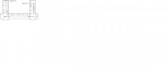
The floor plans of the premises under consideration are shown in Fig. 2, 3, 4.


Figure 4. Layout of the third floor of building 2
The premises presented on the construction plans have the following dimensions: one “window step” (width of a single-window room) – B 0 = 4 m; depth of all rooms (from the entrance to the window) – L 0 = 6 m; width of a multi-window room – B j =B 0 m, where m is the number of windows, j is the room number; corridor width – B to = 2m; the height of all rooms is H=3m.
Workstations and server equipment must be connected to the LAN using IEEE 802.3 1000BASE-T technology. Neighboring buildings must be connected using IEEE 802.3ab technology (gigabit networks based on fiber optic cable), the fiber optic cable installation method is underground. HP active hardware is recommended. The maximum power supply time from UPS drives is 20 minutes. The project should provide for the allocation of special premises for organizing the network administrator’s workplace and placing active LAN equipment. The purpose of the designed LAN is to ensure communication between the specified floors of two buildings in which the educational institution is located, as well as information exchange between classes within the floor. The course work is carried out according to a unified technical specification (TOR) for the design of a local computer network of an educational institution.
1. Description of the proposed design solution
Description of the LAN communication scheme
The network topology is star. The star topology is the fastest of all computer network topologies because data transfer between workstations passes through a central node (if its performance is good) over separate lines used only by these workstations. The frequency of requests to transfer information from one station to another is low (compared to that achieved in other topologies). Network throughput is determined by the computing power of the node and is guaranteed for each workstation. There are no data collisions. Cabling is quite simple as each workstation is connected to a node. In a network built using a star topology, each workstation is connected by a cable (twisted pair) to a hub. The hub provides a parallel connection between PCs and thus all computers connected to the network can communicate with each other.
Data from the network transmitting station is transmitted through the hub along all communication lines to all PCs. Information arrives at all workstations, but is received only by those stations for which it is intended.
However, this topology also has its drawbacks, for example, the performance of a computer network primarily depends on the power of the central file server. It can be a bottleneck in the computer network. If the central node fails, the entire network is disrupted. Cabling costs are high, especially when the central node is not geographically located in the center of the topology.
In accordance with the technical specifications, the following technologies will be used in the design:
· Gigabit Ethernet (IEEE 802.3ab 1000Base T). We will use this technology to connect LAN subscribers and to connect a server to a LAN instead of Gigabit Ethernet IEEE 802.3 1000Base X technology. The IEEE 802.3ab specification was proposed in 1999 in order to ensure data transfer at a speed of 1000 Mbit/s over a UTP 5e category cable and at the same time increase the maximum length of a network segment to 100 m.
· IEEE 802.3ab 1000Base-SX. We will use this technology to connect buildings and switches within the same building (located far from each other), since it allows you to connect network segments located at a distance of up to 550 m, transmission speed 1000 Mbit/s, fiber optic cable (multi-mode fiber) is used for connection ) 50 or 62.5 µm.
To organize a horizontal subsystem (subsystems of this type correspond to the floors of a building), it is best to use shielded twisted pair cable of category 5e. Although it is not as convenient for installation indoors as unshielded twisted pair (and is much more expensive), a network built on shielded components operates much more reliably and meets the emission and noise immunity requirements set by the European standards EN 55022 (Class B) and EN 50082- 1. It allows you to transfer data at a speed of 1000 Mbit/s.
To organize a vertical cable system that connects the floors of the building, fiber optic cable will be used, intended for installation indoors. Advantage of the FOC: transmits data over long distances, is not sensitive to electromagnetic and radio frequency interference. The main disadvantage of a FOC is its cost and the cost of installation.
The function of the campus subsystem will be to connect the subsystems of two buildings into a network. The vertical and campus subsystems will use 1000 Base-SX technology.
Local computing networks enable users of a unified organizational system to carry out high-speed data exchange in real time. And the task of LAN engineers is to provide a stable and well-protected data transmission environment for the use of common application programs, databases, accounting systems, unified communications, etc.
Proper construction of a computer network allows you to avoid many problems that lead to disruption in the working system and unscheduled repair work, so it is better to entrust the installation of a computer network to experts.
What does the physical transmission medium include?
The formation of a transport backbone of an information system at the physical level determines the method of combining all workstations, communication and peripheral equipment for transmitting information signals based on the principle of bit-by-bit conversion of digital data into transmission medium signals (electrical, light, radio signals and other impulses). The logical organization of transmission, encoding and decoding of data is carried out by modems and network adapters. The process of converting signals to synchronize the reception and transmission of data over a network is called physical encoding, and the reverse conversion is called decoding.
Types of data transmission media
The main types of data transmission media between devices can be wired and wireless, so-called Wi-Fi.
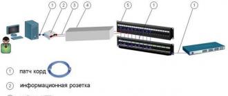
Wireless LAN transmits signals via radio channel ( WiFi) from an access point (Hot-spot) to any active equipment. Certain conveniences, the absence of unnecessary cables, mobility, compatibility with wired networks and simple installation of wireless networks were appreciated by the owners of small offices, cafes, clubs, etc.4. Marking of cables, patch panels, sockets.
- A mandatory element required to perform operational switching during network operation. For convenience, the markings should coincide with the designations on the sketch. project. The markings should be intuitive to the operating personnel even after several years.
5. Installation of active equipment (switches, server, router)
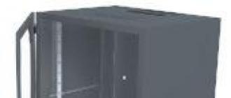
- It is advisable to place it in one place, which will simplify the operation of the entire network. Recommended installation location in a 19" telecommunications cabinet.
5. Acceptance and delivery work
 By contacting the SVIAZ-SERVICE company to perform installation work, you will receive a professional approach at competitive prices:
Tel. 645-35-99
Principles of building a local area network
Consider a typical small office. Let's assume that it employs several managers (let there be three), a secretary, an accountant and a director. Each workplace has a computer, and the office also has one dedicated Internet channel with a permanent real IP address (for example 195.34.10.134) and the domain name myoffice.ru.
Now let's decide what we want to do.
- connect all computers into a local network (LAN);
- organize printing from all workstations to a network printer;
- connect and configure an Internet channel;
- organize Internet access from all computers on the local network;
- protect the local network from external intrusions;
- install and configure network services: WEB server, mail server, file, FTP, proxy, etc.;
- organize remote modem access to the office network from home with the ability to use the office Internet channel
Now let's start designing the network structure.
We will solve the task of building a simple local network based on a stack (set) of TCP/IP protocols.
First, let's select a range of IP addresses for our local network. Let's focus on the addresses reserved for use in private networks: 192.168.0.0-192.168.255.255. For our local network we use addressing 192.168.20.0/24, where “/24” is a shortened form of the subnet mask 255.255.255.0. Each such network (class “C”) can use up to 254 unique hosts, which is quite enough for us. A permanent IP address (195.34.10.134) on the Internet was provided to us by the provider according to the terms of the task.
In a simple case, our network could have the following topology:
As can be seen from Figure 1, most of the network services are located on one computer, which is connected to the Internet through one network interface, to the office local network through another, and to the home computer through a modem connection. Each network interface of this computer has its own IP address: 195.34.10.134 - on the Internet, 192.168.20.1 - on the local network, 192.168.40.1 - for a remote connection. Thus, this computer plays the role of a router and a firewall and servers: web, mail, database, etc. (The router - in our case, plays the role of a gateway to the Internet. You may ask: why is it needed, what does it do? I’ll answer like a teapot: a router deals with routing... packets between subnets, but in our case it will simply “distribute” the Internet to all computers on our local network). But such a structure has disadvantages: firstly, it is dangerous to “put all your eggs in one basket” (such a network is very vulnerable to attacks and is not very reliable - the loser loses everything), secondly, it does not optimally distribute the load, and thirdly, it is inconvenient to administer - any failure or malfunction of the main server almost completely paralyzes the operation of the entire local network. Despite the shortcomings of this option, in the future we will mainly use it, because Here we are looking at the simplest and cheapest solutions for small offices and homes. The following two diagrams are provided for reference only and do not need to be delved into.
Now let’s change the network topology a little to eliminate some of the shortcomings (see Fig. 2).

Here the router only acts as a gateway to the Internet and a firewall, and network services are located inside the local network, ideally, each on a separate computer. Now the failure of one server does not paralyze others. But this network topology also has a disadvantage: workstations and servers are located on the same network segment, which potentially reduces its reliability and performance.
Therefore, it may be better to separate Internet servers into a separate segment (see Fig. 3).

In this case, the local network is located in one network segment, and the Internet servers are in another.
There may be other local network topologies, it all depends on the specific goals and conditions, but to simplify the task we will focus on the first network topology (Fig. 1), despite its shortcomings, because for experiments - this is not important.
Now it’s time to think about what equipment and software (software) we should use to implement our simple local network. Specific implementations will be described in the following articles, but here we will touch on general issues.
The time has passed when company management could not think about the legality of installed programs. Nowadays, copyright violations are considered serious crimes, so out of harm’s way (in order to minimize risks) we will consider only licensed software. Cost optimization when switching to licensed programs for small organizations will be discussed in a separate article 146 of the Criminal Code (just kidding:)))).
You can use the following as a gateway to the Internet:
- computer with Windows (expensive solution);
- computer with FreeBSD/Linux;
- hardware router (the simplest and cheapest solution - from $50).
From some cool gurus working in large organizations, you will most likely hear a recommendation to install MS Windows 2003 Server on the server, install ISA on it (for organizing Internet access), MS Exchange mail server, install Windows XP Pro on client computers and connect them to the domain , and use 1C in terminal mode.
In principle, this is the functionally optimal option... for large organizations, but we are not monsters, we are a small office with 3-10 PCs. Using the price list of Microsoft partners, calculate how many thousands (tens of thousands) of dollars such a solution will cost you. Therefore, in the following articles we will consider mainly cheap options, where free FreeBSD or Linux will be used on the server (gateway), and on client machines Windows XP HomeEdition (or Professional)... or even Linux Ubuntu.
A structured cabling system is a set of switching elements (cables, connectors, cross-connect panels and cabinets), as well as a technique for using them together, which allows you to create regular, easily expandable connection structures in computer networks.
A structured cabling system is a kind of “constructor” with the help of which the network designer builds the configuration he needs from standard cables connected by standard connectors and switched on standard cross-connect panels. If necessary, the connection configuration can be easily changed - add a computer, segment, switch, remove unnecessary equipment, and also change connections between computers and switches.
When building a structured cabling system, it is understood that every workplace in the enterprise must be equipped with sockets for connecting a telephone and computer, even if this is not necessary at this moment. That is, a good structured cabling system is built redundant. This can save money in the future, since changes in the connection of new devices can be made by reconnecting already laid cables.
According to the assignment, the structural diagram of the location of buildings, each of which has its own subnetwork, is shown in Fig. 2.1.
Figure 2.1 – Structural diagram of the location of buildings
The block diagram of the subnetworks of each building is shown in Fig. 2.2 – 2.3. Since there are two 5-story buildings, and they have the same amount of switching equipment and PCs, their structural diagrams are identical.

Figure 2.2 – Block diagram of the subnetwork of a 5-story building

Figure 2.3 – Block diagram of the subnetwork of a 4-story building
A block diagram of connecting subnets into one network is shown in Fig. 2.4.

Figure 2.4 – General block diagram of the network
The technology in buildings is FastEthernet, between buildings is FDDI, Internet access from each building via a radio channel.
3 Selection of equipment and cable
3.1 Selecting switches
Switch is a device designed to connect several nodes of a computer network within one or more network segments. The switch operates at the data link layer of the OSI model. Unlike a hub, which distributes traffic from one connected device to all others, a switch transmits data only directly to the recipient. This improves network performance and security by freeing other network segments from having to process data that was not intended for them.
In this course project, in each room of the buildings there are room switches - workgroup switches, on each floor - a floor switch that unites the workgroup switches of its floor, and a root switch located in the server room on the first floor, to which switches of all floors are connected.
Switching equipment (switches, routers) was selected from the manufacturer Cisco. According to Dell'Oro Group, Cisco occupies 60% of the global network equipment market, that is, more than all other competitors. This manufacturer has the widest range of all network solutions, a wide range of technologies, protocols, ideologies, both standard and and their own, allowing you to expand the capabilities of the network, the broadest troubleshooting capabilities built into almost all Cisco devices.
Based on the optimal balance between price, performance and functionality, the switch models presented below were selected from the Cisco 300 series, designed specifically for small businesses. The line includes a range of low-cost managed switches that provide a powerful foundation for supporting an enterprise network.
Cisco 300 Series Switch Features
Provide the high availability and performance needed for business-critical applications while reducing potential downtime.
allow you to monitor network traffic using such modern functions as quality of service analysis, static third-level routing, and support for the IPv6 protocol.
have clear tools with a web interface; possibility of mass deployment; similar functions in all models.
allow you to optimize energy consumption without affecting performance.
3.1.1 Workgroup switches
According to the assignment for the course work, in a 4-story building in three rooms on each floor there are 35 computers, and in two 5-story buildings in one room on each floor there are 31 computers, for connecting which the SG300-52 switch is selected, which has 48 ports (Fig. 3.1).

Figure 3.1 – Workgroup switch SG300-52
The SG300-52 switch (price: 7522 UAH), manufactured by Cisco, is equipped with 48 10/100/1000 Mbit/s ports for Ethernet networks with automatic speed negotiation for RJ45 ports, which makes installation of the device easier.
This switch provides good performance and can improve workgroup performance and network and master throughput while ensuring easy and flexible installation and configuration. Thanks to the compact size of the case, the device is ideal for placement in limited desktop space; The device can also be rack mounted. Dynamic LEDs display switch status in real time and allow basic diagnostics of device operation.
The main technical characteristics of the SG300-52 switch are presented in Table 3.1.
Table 3.1 – Technical characteristics of the SG300-52 switch
|
Managed Switch |
|
|
Interface |
4 x SFP (mini-GBIC), 48 x Gigabit Ethernet (10/100/1000 Mbps) |
|
SNMP 1, RMON 1, RMON 2, RMON 3, RMON 9, Telnet, SNMP 3, SNMP 2c, HTTP, HTTPS, TFTP, SSH, |
|
|
Routing protocol |
Static IPv4 routing, 32 routes |
|
MAC address table |
16000 records |
|
128 MB (RAM), Flash memory – 16 MB |
|
|
Encryption algorithm | |
|
Additional features |
Up to 32 static routes and up to 32 IP interfaces Layer 3 DHCP translation User Datagram Protocol (UDP) translation Smartports simplifies configuration and security management Built-in configuration utility, web-based access (HTTP/HTTPS) Dual protocol stack IPv6 and IPv4 Upgrade software |
|
Supported Standards |
IEEE 802.3 10BASE-T Ethernet, IEEE 802.3u 100BASE-TX Fast Ethernet, IEEE 802.3ab 1000BASE-T Gigabit Ethernet, IEEE 802.3ad LACP, IEEE 802.3z Gigabit Ethernet, IEEE 802.3x Flow Control, IEEE 802.1D (STP, GARP, and GVRP), IEEE 802.1Q/p VLAN, IEEE 802.1w RSTP, IEEE 802.1s Multiple STP, IEEE 802.1X Port Access Authentication, IEEE 802.3af, IEEE |
|
Internal power supply. 120-130 VAC, 50/60 Hz, 53 W. |
|
|
Ambient conditions environment |
Operating temperature: 0°C ~40°C |
|
Dimensions (WxDxH) |
440*260*44 mm |
For two 5-storey buildings, in which the remaining rooms on each floor have 18 and 25 computers, respectively, 18 computers are selected for connection - a switch with 24 ports - SF300-24P (price: 4042 UAH), and for connection 25 computers - two switches, each with 16 ports - SG300-20 (price: 3023 UAH), which are shown in Fig. 3.2. The remaining ports are for reserve.


Figure 3.2 – Workgroup switch SF300-24P (a) and SG300-20 (b)
The SF300-24P is a 24-port managed network switch. These switches provide everything you need to run business-critical applications, protect sensitive information, and optimize bandwidth for more efficient network transfer. Plug-and-play support and auto-negotiation allow the switch to automatically detect the type of device being connected (such as an Ethernet network adapter) and select the most appropriate speed. LED indicators are used to monitor cable connections and standard diagnostics. The switch can be desktop-mounted or rack-mounted.
The SG300-20 switch is designed for small workgroups and is equipped with 18 10/100/1000BASE-TX Ethernet ports and 2 mini-GBICs. The functionality of these switches is similar to the functionality of the SF300-24P switch, since they both belong to the same Cisco 300 series.
The main technical characteristics of the SF300-24P switch are presented in Table 3.2, and the SG300-20 switch - in Table. 3.3.
Table 3.2 – Technical characteristics of the SF300-24P switch
|
Managed Switch |
|
|
Interfaces |
24 Ethernet ports 10Base-T/100Base-TX - RJ-45 connector, PoE support; console control port - 9 pin D-Sub (DB-9); 4 Ethernet ports 10Base-T/100Base-TX/1000Base-T - RJ-45 connector, 2 ports for SFP (mini-GBIC) modules. |
|
Remote Administration Protocol | |
|
Routing protocol |
Static IPv4 routing |
|
MAC address table |
16000 records |
|
128 MB (RAM), Flash memory – 16 MB |
|
|
Encryption algorithm | |
|
Control |
SNMP versions 1, 2c and 3 Built-in RMON software agent for traffic management, monitoring and analysis Dual protocol stack IPv6 and IPv4 Software upgrades DHCP port mirroring (options 66, 67, 82, 129 and 150) Smartports feature simplifies configuration and security management Cloud-based services Other management functions: Traceroute; management via a single IP address; HTTP/HTTPS; SSH; RADIUS; DHCP client; BOOTP; SNTP; Xmodem update; cable diagnostics; ping; system log; Telnet client (SSH support) |
|
Supported Standards |
IEEE 802.3 10BASE-T Ethernet IEEE 802.3u 100BASE-TX Fast Ethernet IEEE 802.3ab 1000BASE-T Gigabit Ethernet IEEE 802.3ad LACP IEEE 802.3z Gigabit Ethernet IEEE 802.3x Flow Control IEEE 802.1D (STP, GARP, and GVRP) IEEE 802.1Q /p VLAN IEEE 802.1w RSTP IEEE 802.1s Multiple STP IEEE 802.1X Port Access Authentication IEEE 802.3af IEEE 802.3at |
|
Performance |
Non-blocking switching at speeds up to 9.52 million pps (64 byte packet size) Switch matrix: up to 12.8 Gbps Packet buffer size: 4 MB |
|
Availability |
Automatically turns off power to RJ-45 Gigabit Ethernet ports when there is no connection, turns on again when activity resumes |
Table 3.3 – Technical characteristics of the SF300-20 switch
|
Managed Switch |
|
|
Interfaces |
18 Ethernet ports 10Base-T/100Base-TX - RJ-45 connector, 2 ports for SFP (mini-GBIC) modules. |
|
Remote Administration Protocol |
SNMP 1, RMON 1, RMON 2, RMON 3, RMON 9, Telnet, SNMP 3, SNMP 2c, HTTP, HTTPS, TFTP, SSH, |
|
Routing protocol |
Static IPv4 routing |
|
MAC address table |
16000 records |
|
128 MB (RAM), Flash memory - 16 MB, buffer volume - 1 MB |
|
|
Encryption algorithm |
802.1x RADIUS, HTTPS, MD5, SSH, SSH-2, SSL/TLS |
|
Control protocols |
IGMPv1/2/3, SNMPv1/2c/3 |
|
Supported Standards |
IEEE 802.1ab, IEEE 802.1D, IEEE 802.1p, IEEE 802.1Q, IEEE 802.1s, IEEE 802.1w, IEEE 802.1x, IEEE 802.3, IEEE 802.3ab, IEEE 802.3ad, IEEE 802.3at, IEEE 802.3u, IEEE 802.3x IEEE 802.3z |
|
Supported network protocols |
IPv4/IPv6, HTTP, SNTP, TFTP, DNS, BOOTP, Bonjour |
|
Functional |
Thread control support Port Mirroring Merging channels Jumbo Frames support Broadcast storm control Speed Limit DHCP client Spanning tree protocol, etc. |
|
Internal power supply. 120-130 VAC, 50/60 Hz, 53 W. |
|
|
Ambient conditions environment |
Operating temperature: 0°C ~40°C |
3.1.2 Floor switches
To connect workgroup switches, floor switches are used, for which the SRW208G-K9 switch (price: 1483 UAH), which has 8 ports, is selected (Fig. 3.3).

Figure 3.3 – Floor switch SRW208G-K9
The SRW208G-K9 switch is equipped with 8 RJ45 ports for Fast Ethernet, 1 Gigabit Ethernet port and two SFP (mini-GBIC) ports, which operate in auto-configuration and speed detection mode.
Cisco Catalyst 2960 is a series of new fixed-configuration smart Ethernet switches. They meet the need for data transmission at speeds of 100 Mbit/s and 1 Gbit/s and allow the use of LAN services, for example, for data transmission networks built in corporate branches. The Catalyst 2960 family provides high data security with built-in NAC, QoS support, and high levels of system resiliency.
Key Features:
High level of security, advanced access control lists (ACLs);
Organization of network control and optimization of channel width using QoS, differentiated rate limiting and ACL.
To ensure network security, switches use a wide range of user authentication methods, data encryption technologies and organization of access control to resources based on user ID, port and MAC addresses.
Switches are easy to manage and configure
Auto-configuration function is available via Smart ports for some specialized applications.
The main technical characteristics of this switch, manufactured by Cisco, coincide with the characteristics presented in table. 3.2. for a switch from the same company.
3.1.3 Root switches
To connect floor switches, root switches are used, for which a switch was selected in each building - SG300-20, which has 16 ports. This switch was also selected as a workgroup switch; its description is presented in paragraph 3.1.1.
3.2 Selecting routers
Router (router) is a device that has at least two network interfaces and forwards data packets between different network segments, making forwarding decisions based on information about the network topology and certain rules set by the administrator.
Routers help reduce network congestion by dividing the network into collision domains or broadcast domains, and by filtering packets. They are mainly used to combine networks of different types, often incompatible in architecture and protocols. Often, a router is used to provide access from a local network to the Internet, performing the functions of address translation and a firewall.
To connect buildings into one network, a router is used, which was chosen as Cisco 7507 7500 series (price: 121,360 UAH), which has the ability to connect an FDDI module (Fig. 3.4).


Figure 3.4 – Cisco 7507 Router
This router was chosen based on the ability to connect an FDDI module, the best price from the entire line of this series, and the fact that the Cisco 7500 series modular routers are the most powerful Cisco routers. They meet the highest requirements for modern data networks. The flexible modular architecture of routers in this series allows them to be used in large network nodes, selecting optimal solutions.
The Cisco 7500 series consists of three models. The Cisco 7505 has one routing and switching processor (RSP1= Route/Switch Processor), one power supply and four slots for interface processors (5 slots in total). The Cisco 7507 and Cisco 7513, with seven and thirteen slots respectively, provide greater throughput and can be configured with two RSP2 or PSP4 and a redundant power supply. Combined with the new redundant CyBus, the Cisco 7507/7513 routers offer unmatched performance and reliability. This is achieved thanks to a new, distributed multiprocessor architecture, which includes three elements:
Integrated Routing and Switching Processor (RSP);
New multi-purpose (Versatile) interface processor (VIP);
New high-speed Cisco CyBus.
In a dual-RSP (integrated Routing and Switching Processor) configuration, the Cisco 7500 distributes functions between the primary and secondary RSPs, increasing system performance, and if one processor fails, the other takes over all functions.
The Cisco 7507 Router is a modular router designed for building large network backbones and works with virtually all LAN and WAN technologies and all major network protocols.
The Cisco 7507 series supports a very wide range of connections, including: Ethernet, Token Ring, FDDI, Serial, HSSI, ATM, Channelized T1, Fractionalized E1 (G.703/G.704), ISDN PRI, Channel Interface for IBM mainframes.
Network interfaces are located on modular processors that provide a direct connection between the Cisco Extended Bus (CxBus) high-speed backbone and the external network. Seven slots are available for interface processors on the Cisco 7507. Hot-swappable functionality allows CxBus processor modules to be added, replaced, or removed without interrupting network operation. Standard Flash memory is used to store information. All models come with a standard 19" rack mounting kit.
There are the following communication interface modules:
Ethernet Intelligent Link Interface - 2/4 Ethernet ports with high-speed filtering capabilities (29000 p/s), support for Transparent Bridging and Spanning Tree algorithms, configuration using the Optivity system;
Token Ring Intelligent Link Interface - 2/4 Token Ring ports 4/16 Mb/s;
FDDI Intelligent Link Interface - 2 ports supporting two SAS connections or one DAS connection, filtering at speeds up to 500,000 p/s;
ATM Intelligent Link Interface.
3.3 Cable selection
A cable is a structure of one or more conductors (cores) insulated from each other, or optical fibers enclosed in a sheath. In addition to the actual cores and insulation, it may contain a screen, power elements and other structural elements. The main purpose is the transmission of high-frequency signals in various fields of technology: for cable television systems, for communication systems, aviation, space technology, computer networks, household appliances, etc. When using switches, the Fast Ethernet protocol can operate in duplex mode, in which there is no restrictions on the total length of the network, but there remain restrictions on the length of the physical segments connecting neighboring devices (switch-adapter and switch-switch).
According to the instructions, Fast Ethernet technology with the 100Base-TX specification was used inside the buildings; unshielded twisted pair (UTP) category 5 was used as the communication line.
Between buildings - FDDI technology, used as a communication line
optical cable for outdoor installation.
UTP cable for indoor installation, 2 pairs, category 5, used in subscriber wiring to provide access to data network services. For installation, a cable from the manufacturer Neomax was chosen - NM10000 (Fig. 3.4) due to its high strength and long service life; its characteristics are presented in Table 3.4.
|
|
|


Figure 3.4 – UTP, 2 pairs, cat. 5e: 1 - Outer shell; 2 - Twisted pair
Table 3.4 – Main characteristics of UTP cable, cat.5
|
Conductor |
electrolytic copper wire |
|
Core insulation |
high density polyethylene |
|
Conductor (core) diameter |
0.51 mm (24 AWG) |
|
Diameter of conductor with sheath |
0.9 ± 0.02 mm |
|
Outer diameter (size) of cable | |
|
Outer shell thickness | |
|
Twisted pair color: |
blue-white/blue, orange-white/orange |
|
Cable bending radius: |
4 external cable diameters |
|
Working temperature: |
20°C – +75°C |
3.4 Selecting wireless equipment
Each building uses a radio channel to access the Internet. The Maximus Sector 515812-B directional antenna was selected as the antenna on the BPS (Fig. 3.5, a), and on buildings, the TP-Link TL-WA7510N WiFi access point (Fig. 3.5, b) was selected as an external access point. This equipment was selected for the optimal price-functionality ratio.
The 5 GHz frequency range was chosen as the operating range, since the 2.4 GHz range is more saturated (loaded) due to the ubiquity of wireless networks. The old standard 802.11b, the recently retired 802.11g and 802.11n work at this frequency. Regardless of whether you use 802.11b, 802.11g or 802.11n, you transmit data over the same channel. Another disadvantage of 2.4 GHz is the presence of "side noise" in the wireless channel, which degrades the channel's permeability, since it shares the spectrum with many other unlicensed devices - microwave ovens, mini-monitors, cordless phones, etc. Also the number of used radio channels in the range 2.4 GHz is limited. The 5 GHz band is less crowded and has more usable channels at the expense of a slightly shorter range.


Figure 3.5 – Wireless equipment: a) antenna; b) access point
Model TL-WA7510N (price: 529 UAH) is a long-range outdoor wireless device that operates in the 5 GHz frequency range and transmits data via a wireless connection at speeds of up to 150 Mbit/s. The device has a dual polarization antenna with 15 dBi gain, which is a key element for building Wi-Fi connections over long distances. It is designed to transmit a signal with radiation angles of 60 degrees horizontally and 14 degrees vertically, increasing the signal strength by concentrating the radiation in a given direction.
Thanks to the all-weather housing and temperature-resistant internal hardware, the access point can operate in a variety of environmental conditions, in sunny or rainy weather, in strong winds or in snowfall. Built-in ESD protection up to 15KV and lightning protection up to 4000V can prevent power surges during thunderstorms, ensuring stable operation of the device. In addition, the device has a grounding terminal for a more professional level of protection for some experienced users.
The device can operate not only in access point mode. The TL-WA7510N also supports router-client access point, router-to-access point, bridge, repeater and client operating modes, which can significantly expand the scope of the device, providing users with the most multifunctional product possible.
Powered by a PoE injector, the outdoor access point can use an Ethernet cable to simultaneously transmit data and electricity wherever the access point is located over a distance of up to 60 meters. The presence of this feature increases the possible placement options for the access point, allowing you to place the access point in the most suitable location to obtain the best signal quality.
The main characteristics of the TL-WA7510N are presented in table. 3.5.
Table 3.5 – Characteristics of TL-WA7510N
|
Interface |
1 x 10/100 Mbps auto-sensing RJ45 port (Auto-MDI/MDIX, PoE) 1 x external Reverse SMA connector 1 x ground terminal |
|
|
Wireless standards |
IEEE 802.11a, IEEE 802.11n |
|
|
Dual polarization directional antenna, 15 dBi gain |
||
|
Dimensions (WxDxH) |
250 x 85 x 60.5 mm (9.8 x 3.3 x 2.4 inches) |
|
|
Antenna beamwidth |
Horizontal: 60° Vertical: 14° |
|
|
15 kV ESD protection Lightning protection up to 4000 V Built-in grounding terminal |
||
|
Continuation of the table. 3.5 |
||
|
frequency range |
5.180-5.240 GHz 5.745-5.825 GHz Note: Frequency varies by region or country. |
|
|
Signal transmission speed |
11a: up to 54 Mbps (dynamic) 11n: up to 150 Mbps (dynamic) |
|
|
Sensitivity (reception) |
802.11a 54 Mbps: -77 dBm 48 Mbps: -79 dBm 36 Mbps: -83 dBm 24 Mbps: -86 dBm 18 Mbps: -91 dBm 12 Mbps: -92 dBm 9 Mbps: -93 dBm 6 Mbps: -94 dBm |
802.11n 150 Mbps: -73 dBm 121.5 Mbps: -76 dBm 108 Mbps: -77 dBm 81 Mbps: -81 dBm 54 Mbps: -84 dBm 40.5 Mbps :-88 dBm 27 Mbit/s:-91 dBm 13.5 Mbit/s:-93 dBm |
|
Operating modes |
Access Point Router Access Point Client Router (WISP Client) Access Point/Client/Bridge/Relay |
|
|
Wireless Security |
Enable/disable SSID; MAC address filter 64/128/152-bit WEP encryption WPA/WPA2, WPA-PSK/WPA2-PSK(AES/TKIP) |
|
|
Additional features |
Supports PoE up to 60 meters 4-level LED indicator |
|
Maximus Sector 515812-B sector antenna (price: 991 UAH) of vertical polarization is made in an antenna casing made of UV-resistant plastic with a cast aluminum bracket. High-quality materials allow the antenna to be used in harsh weather conditions. It can be used for small, medium and large sized base stations. The antenna produces a strong and stable signal over medium and long distances. The main characteristics are presented in table. 3.6.
Table 3.6 – Technical characteristics of Maximus Sector 515812-B
Modern computer technology cannot be imagined without combining all kinds of devices in the form of stationary terminals, laptops or even mobile devices into a single network. This organization allows not only to quickly exchange data between different devices, but also to use the computing capabilities of all pieces of equipment connected to the same network, not to mention the ability to access peripheral components such as printers, scanners, etc. But on what principles is this done? Union? To understand them, it is necessary to consider the local network, often called topology, which will be discussed further. Today, there are several main classifications and types of combining any devices that support network technologies into one network. Of course, we are talking about those devices that have special wired or wireless network adapters and modules installed.
Local computer network schemes: main classification
First of all, when considering any type of organization of computer networks, it is necessary to start exclusively from the method of combining computers into a single whole. Here we can distinguish two main directions used when creating a local network diagram. The network connection can be either wired or wireless.
In the first case, special coaxial cables or twisted pairs are used. This technology is called Ethernet connection. However, if coaxial cables are used in a local area network circuit, their maximum length is about 185-500 m with a data transfer rate of no more than 10 Mbit/s. If twisted pairs of classes 7, 6 and 5e are used, their length can be 30-100 m, and the throughput ranges from 10-1024 Mbit/s.

The wireless scheme for connecting computers on a local network is based on transmitting information via a radio signal, which is distributed between all connected devices, distributing devices, which can be routers (routers and modems), access points (regular computers, laptops, smartphones, tablets), switching devices (switches, hubs), signal repeaters (repeaters), etc. With this organization, fiber-optic cables are used, which are connected directly to the main equipment distributing the signal. In turn, the distance over which information can be transmitted increases to approximately 2 km, and in the radio frequency range the frequencies of 2.4 and 5.1 MHz (IEEE 802.11 technology, better known as Wi-Fi) are mainly used.
Wired networks are considered to be more protected from external influences, since it is not always possible to directly access all terminals. Wireless structures lose quite a lot in this regard, because if desired, a competent attacker can easily figure out the network password, gain access to the same router, and through it get to any device that is currently using the Wi-Fi signal. And very often, in the same government agencies or in defense enterprises in many countries, the use of wireless equipment is strictly prohibited.
Classification of networks according to the type of connection between devices
Separately, we can distinguish a fully connected topology of computer connection diagrams on a local network. Such a connection organization only implies that absolutely all terminals included in the network are connected to each other. And as is already clear, such a structure is practically unprotected in terms of external intrusion or when attackers penetrate the network through special virus worms or spyware applets, which could initially be recorded on removable media, which the same inexperienced enterprise employees could unknowingly connect to your computers.
That is why other connection schemes in the local network are most often used. One of these can be called a cellular structure, from which certain initial bonds have been removed.
General diagram of connecting computers on a local network: the concept of the main types of topology
Now let's briefly look at wired networks. They can use several of the most common types of local network diagrams. The most basic types are star, bus and ring structures. True, it is the first type and its derivatives that are most widely used, but you can often find mixed types of networks where combinations of all three main structures are used.
Star topology: pros and cons
The “star” local network scheme is considered the most common and widely used in practice when it comes to using the main types of connection, so to speak, in its pure form.

The essence of this combination of computers into a single whole is that they are all connected directly to the central terminal (server) and have no connections with each other. Absolutely all transmitted and received information passes directly through the central node. And it is this configuration that is considered the most secure. Why? Yes, only because the introduction of the same viruses into a network environment can be done either from a central terminal, or reached through it from another computer device. However, it seems very doubtful that such a local network scheme for an enterprise or government agency will not provide a high level of protection for the central server. And you can only install spyware from a separate terminal if you have physical access to it. In addition, from the central node, quite serious restrictions can be imposed on each network computer, which can be especially often observed when using network operating systems, when the computers do not even have hard drives, and all the main components of the operating system used are loaded directly from the main terminal.
But this also has its drawbacks. This is primarily due to increased financial costs for laying cables if the main server is not located in the center of the topological structure. In addition, the speed of information processing directly depends on the computing capabilities of the central node, and if it fails, connections are disrupted on all computers included in the network structure.
Bus circuit
The “bus” type connection scheme in a local network is also one of the most common, and its organization is based on the use of a single cable, through branches of which all terminals, including the central server, are connected to the network.

The main disadvantage of this structure is the high cost of laying cables, especially in cases where the terminals are located at a fairly large distance from each other. But if one or more computers fail, connections between all other components in the network environment are not disrupted. In addition, when using such a local network scheme, the network passing through the main channel is very often duplicated in different sections, which avoids its damage or the impossibility of delivering it to its destination. But security in such a structure, alas, suffers quite greatly, since malicious virus codes can penetrate all other machines through the central cable.
Ring structure
The ring circuit (topology) in a sense can be called obsolete. Today it is not used in almost any network structure (except perhaps only in mixed types). This is connected precisely with the very principles of combining individual terminals into one organizational structure.

Computers are connected to each other in series and with only one cable (roughly speaking, at the input and output). Of course, this technique reduces material costs, but if at least one network unit fails, the integrity of the entire structure is compromised. If I may say so, in a certain area where there is a damaged terminal, the transmission (passage) of data is simply stopped. Accordingly, when dangerous computer threats penetrate the network, they also pass sequentially from one terminal to another. But if there is reliable protection in one of the areas, the virus will be eliminated and will not pass further.
Mixed network types
As mentioned above, the main types of local network schemes are practically never found in their pure form. Mixed types, which may contain elements of the main types of network circuits, appear to be much more reliable in terms of security, cost, and ease of access.

Thus, very often you can find networks with a tree structure, which initially can be called a kind of “star”, since all the branches come from one point, called the root. But the organization of branches in such a local network connection scheme can contain both ring and bus structures, dividing into additional branches, often defined as subnets. It is clear that such an organization is quite complex, and when creating it it is necessary to use additional technical devices such as network switches or splitters. But, as they say, the end justifies the means, because thanks to such a complex structure, important and confidential information can be protected very reliably, isolating it in subnet branches and practically limiting access to it. The same applies to the failure of components. With this construction of local network schemes, it is absolutely not necessary to use only one central node. There may be several of them, with completely different levels of protection and access, which further increases the degree of overall security.
Logistics topology
When organizing network structures, it is especially important to pay attention to the data transmission methods used. In computer terminology, such processes are usually called logistic or logical topology. At the same time, physical methods of transmitting information in various structures can differ quite significantly from logical ones. It is logistics that, in essence, determines the reception/transmission routes. Very often you can observe that when building a network in the form of a “star”, information is exchanged using a bus topology, when the signal can be received simultaneously by all devices. In ring logical structures, situations can be encountered where signals or data are received only by those terminals for which they are intended, despite sequential passage through all related links.
Most famous networks
Above, we have only considered the construction of local network schemes based on Ethernet technology, which in its simplest terms uses addresses, protocols and TCP/IP stacks. But in the world you can find a huge number of network structures that have different principles of network organization from the above. The most famous of all (except Ethernet using a logical bus topology) are Token Ring and Arcnet.

The Token Ring network structure was once developed by the well-known company IBM and is based on the logical scheme of a local network “token ring”, which determines the access of each terminal to the transmitted information. In physical terms, a ring structure is also used, but it has its own characteristics. To combine computers into a single unit, it is possible to use either twisted pair or fiber optic cable, but the data transfer speed is only 4-16 Mbit/s. But the star-type marker system allows you to transmit and receive data only to those terminals that have the right to do so (marked with a marker). But the main disadvantage of such an organization is that at a certain moment only one station can have such rights.
No less interesting is the Arcnet local network scheme, created in 1977 by Datapoint, which many experts call the most inexpensive, simple and very flexible structure.

Coaxial or fiber optic cables can be used to transmit information and connect computers, but the possibility of using twisted pair cables is also possible. However, in terms of reception/transmission speed, this structure cannot be called particularly productive, since at maximum packets can be exchanged at a connection speed of no more than 2.5 Mbit/s. A “star” circuit is used as a physical connection, and a “marker bus” is used for a logical connection. With the rights to receive/transmit, the situation is exactly the same as in the case of Token Ring, except that the information transmitted from one machine is available to absolutely all terminals included in the network environment, and not to just one machine.
Brief information on setting up a wired and wireless connection
Now let's briefly look at some important points in creating and using any of the described local network schemes. Third-party programs when using any of the well-known operating systems are not needed to perform such actions, since the basic tools are provided in their standard sets initially. However, in any case, it is necessary to take into account some important nuances regarding the configuration of IP addresses, which are used to identify computers in network structures. There are only two varieties - static and dynamic addresses. The first, as the name implies, are constant, and the second can change with each new connection, but their values are exclusively in one range, set by the communication service provider (provider).
In wired corporate networks, to ensure high speed data exchange between network terminals, static addresses are most often used, assigned to each machine located on the network, and when organizing a network with a wireless connection, dynamic addresses are usually used.
To set the specified parameters for a static address in Windows systems, the parameters of the IPv4 protocol are used (in the post-Soviet space, the sixth version has not yet become particularly widespread).

In the protocol properties, it is enough to specify the IP address for each machine, and the subnet mask and default gateway parameters are common (unless a tree structure with multiple subnets is used), which looks very convenient from the point of view of quickly setting up a connection. Despite this, dynamic addresses can also be used.

They are assigned automatically, for which there is a special item in the TCP/IP protocol settings, and at each specific point in time they are assigned to network machines directly from the central server. The range of allocated addresses is provided by the provider. But this absolutely does not mean that the addresses are repeated. As you know, there cannot be two identical external IPs in the world, and in this case we are talking about either the fact that they change only within the network or are transferred from one machine to another when some external address turns out to be free.
In the case of wireless networks, when routers or access points that distribute (broadcast or amplify) the signal are used for the initial connection, the setup looks even simpler. The main condition for this type of connection is to automatically obtain an internal IP address. Without this, the connection will not work. The only parameter that can be changed is the DNS server addresses. Despite the initial setting to receive them automatically, it is often (especially when the connection speed decreases) that it is recommended to set such parameters manually, using, for example, free combinations distributed by Google, Yandex, etc.
Finally, even if there is only a certain set of external addresses by which any computer or mobile device is identified on the Internet, they can also be changed. There are many special programs for this. The local network scheme can have any of the above variations. And the essence of using such tools, which most often are either VPN clients or remote proxy servers, is to change the external IP, which, if anyone doesn’t know, has a clear geographical reference, to an unoccupied address located in in a completely different location (even at the end of the world). You can use such utilities directly in browsers (VPN clients and extensions) or make changes at the level of the entire operating system (for example, using the SafeIP application), when some applications running in the background need to access blocked or inaccessible for a certain region Internet resources.
Epilogue
If we summarize all of the above, we can draw several main conclusions. The first and most important thing concerns the fact that the basic connection diagrams are constantly being modified, and they are almost never used in the initial version. The most advanced and most secure are complex tree structures, which can additionally use several subordinate (dependent) or independent subnets. Finally, no matter what anyone says, at the present stage of development of computer technology, wired networks, even despite the high financial costs of their creation, are still head and shoulders above the simplest wireless ones in terms of security. But wireless networks have one undeniable advantage - they allow you to connect computers and mobile devices that can be geographically distant from each other over very long distances.