General concepts
There is no need to talk about the role and importance of a well-organized, flawlessly operating enterprise local computer network. Often it is the LAN that is the guarantor of a successful business. And vice versa, with poor organization and insufficient attention to issues of its construction and renewal, a collapse occurs in the organization of work in the enterprise. To paraphrase a well-known saying, we can say: “LAN is like air, people don’t notice it when it’s there, and they suffocate when it’s not there.”
Everywhere we are faced with various versions of local computer networks. Often, from a house LAN, growing to the scale of a district or an entire city, a computer network becomes a city network (MAN).
A local area network must have a number of properties:
Scalability – at the initial stage, the organization can invest a minimum of funds on the construction of local networks that would meet its current goals and objectives. In the future, if the need arises, she can always easily expand the network and connect additional equipment.
Flexibility – in order to respond in a timely manner to changing technology requirements for the existing local network, it is necessary to have its flexibility. In other words, the network must be adapted for most types of network cables: twisted pair, coaxial, and fiber optic, and it is desirable to support technologies ranging from Ethernet, FastEthernet, to GigabitEthernet and higher.
fault tolerance – the local network system must include backup lines in case the main lines fail for a number of reasons. For example, you can connect a server (server farm) to several switches/routers that have backup paths - if one hub/router fails, you can always quickly switch to another automatically, without interrupting the communication session.
Reliability – long-term use of a local network in accordance with the growing need for it implies the need to search for optimal options to increase its reliability, since forced downtime is too expensive for an organization when every minute is valuable. Therefore, existing software, hardware and tools that can improve the reliability of local networks cannot be neglected.
Protection – an important property is the security of networks from unauthorized intrusion via the Internet, as well as internal actions of users. It is solved using a set of measures, including software and hardware - a hub, switch, router, firewall, remote access server, as well as administrative measures, which generally allows complete control over current processes and guarantees the safety of the organization’s most important data.
Controllability – the local network must have powerful tools for monitoring it, to quickly identify interference and faults, in order to eliminate the possible downtime mentioned above. There are many products designed to quickly collect technical information about the state of the network and its parameters - examples include SNMP, RMON tools. In addition, it is possible to manage the network via a Web interface, which can be used almost anywhere for remote access.
In the simplest case, a local area network consists of two computers equipped with a network card, connected to each other by an appropriately terminated cable (coaxial or twisted pair). It must be remembered that in such a scheme a non-standard patch cord is used, and the so-called crossover. And of course, we must not forget that the distance between PCs should be no more than 100 m.
The solution when a LAN consists of two PCs can also be implemented using wireless technology; in this case, both computers are equipped with wireless network cards (adapters) and are connected in point-to-point mode.
Network card , also known as a network card, network adapter, Ethernet adapter, NIC (English network interface controller) is a peripheral device that allows the computer to communicate with other devices on the network.
SNMP (Simple Network Management Protocol) - Simple Network Management Protocol) is a communication network management protocol based on the TCP/IP architecture.
RMON - computer network monitoring protocol , an extension of SNMP, which, like SNMP, is based on the collection and analysis of information about the nature of information transmitted over the network. As in SNMP, information is collected by hardware and software agents, the data from which is sent to the computer where the network management application is installed. The difference between RMON and its predecessor lies, first of all, in the nature of the information collected - if in SNMP this information characterizes only events occurring on the device where the agent is installed, then RMON requires that the received data characterize the traffic between network devices.
The above method of organizing a network of two computers is simple and does not require any special costs; such implementation of a LAN is becoming less and less common. However, the realities of today are such that enterprise LANs include tens and hundreds of computers and network devices (switches, gateways, print servers, servers, network storage devices, etc.), in addition, almost all LANs have access to the global INTERNET network.
Organizing a local network (even further setting up the local network) necessarily begins with identifying key points. Here are some of them:
· Determining the number of stations (ports, hosts) of the future network;
· Planning a shared data warehouse;
· Prospective software;
· Proposed services (IP telephony, video surveillance, etc.);
· Demand for a unified information space for the company’s structural divisions;
· The likelihood of using a local network to build a unified corporate information platform (intranet).
There are several options for organizing a local network. The data transmission medium can be UTP/STP twisted cable (usually category 5e and higher) or fiber optic cable. It is also possible to organize local networks using wireless technology. At the same time, the construction and configuration of a local network will vary greatly depending on the technology used - wireless and wired.
The construction of a local network will be largely determined by its size and the way computers are placed. Among other factors influencing the organization and configuration of a local network, it is worth noting the availability of servers, the number of jobs, as well as the number of buildings in which the LAN operates.
At the stage of creating a local network and setting up a local network, it is important to have a clear understanding of the architecture (topology) of the network. The network topology depends on the location of the PC and its functional purpose. The choice of topology in the process of creating a local network and configuring a local network occurs individually - a specific object has its own architecture.
To carry out the installation of a local network, the necessary network equipment for each option is selected, preferably from one reliable manufacturer.
The D-Link company offers a full range of active network equipment for building (upgrading) local computer networks of any level of complexity. In addition, the fact that there is a wide-ranging service for D-Link equipment is also important.
After all the key points related to the organization of the future network have been determined, they begin to create a cable system (in the case of a wired LAN solution).
Intranet (English Intranet, the term intranet is also used ) - unlike the Internet, this is an internal private network of an organization. Typically, an Intranet is a miniature Internet that is built on the use of the IP protocol to exchange and share some of the information within that organization. These can be lists of employees, lists of phone numbers of partners and customers. Most often, this term refers to only the visible part of the Intranet - the internal website of the organization. Based on the basic HTTP and HTTPS protocols and organized on the client-server principle, the intranet site is accessible from any computer. Thus, the Intranet is like a “private” Internet, limited to the virtual space of a single organization. Intranet allows the use of public communication channels included in the Internet (VPN), but at the same time the protection of transmitted data and measures to prevent outside penetration of corporate nodes are ensured.
Structured cabling system (SCS)
Cable system is a system whose elements are cables and components that are connected to the cable. Cable components include everything passive switching equipment , used for connection or physical termination (termination) of a cable - telecommunication sockets at workplaces, crossover and patch panels (jargon patch panels ) in telecommunications premises, couplings and splices.
Recently, when organizing a LAN, in relation to the cable system, the term is most often used structured cable system (SCS).
Structured cabling system (SCS) - the basis of an enterprise’s information infrastructure, which makes it possible to combine into a single system many information services for various purposes: local computer and telephone networks, security systems, video surveillance, etc.
SCS is a hierarchical cabling system of a building or group of buildings, divided into structural subsystems. It consists of a set of copper and optical cables, cross-panels, patch cords, cable connectors, modular sockets, data sockets and auxiliary equipment. All of the above elements are integrated into a single system and operated according to certain rules.
Term "structured" means, on the one hand, the ability of the system to support various telecommunications applications (transmission of voice, data and video), on the other hand, the ability to use various components and products from different manufacturers, and thirdly, the ability to implement the so-called multimedia environment, in which several types of transmission media are used - coaxial cable, UTP, STP and optical fiber. The structure of the cable system is determined by the information technology infrastructure (IT, Information Technology), which dictates the content of a specific cable system project in accordance with the requirements of the end user, regardless of the active equipment that can be used subsequently.
Typical SCS installation work includes:
· installation of cable channels (ducts, trays, corrugated pipes, pipes, etc.);
· punching holes in walls;
· laying cables in cable channels;
· installation of sockets and cable termination of socket modules;
· assembly and installation of the mounting cabinet;
· installation and filling of patch panels and organizers.
SCS installation stages:
· Study of the site for installation of SCS;
· Development of a technical project;
· Selection of necessary equipment and installation on site;
· Testing and certification, delivery of work to the customer;
· Post-installation support and training
SCS components
When creating SCS are used. Cables ,connectors ,sockets and patch cords used in computer networks. Let us briefly recall:
Copper unshielded UTP cable (English Unshielded Twisted Pair) Depending on the electrical and mechanical characteristics, it is divided into 5 categories (Category 1 - Category5).
Shielded Twisted Pair (STP) It protects transmitted signals well from external interference, and also emits less electromagnetic waves to the outside, which in turn protects network users from radiation harmful to health. Cables occupy a special place categories 6 and 7, which the industry began to produce relatively recently. For Category 6 cable, the characteristics are determined up to a frequency of 200 MHz, and for Category 7 cables - up to 600 MHz. Category 7 cables must be shielded, both each pair and the entire cable as a whole. Category 6 cables can be either shielded or unshielded. The main purpose of these cables is to support high-speed protocols over cable lengths longer than Category 5 UTP cable.
8P8C(8 Position 8 Contact) , often mistakenly called RJ45 or RJ-45 - a unified connector used in telecommunications, has 8 contacts and a latch.
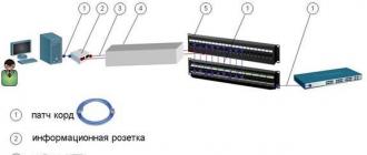
Information outlets, as a rule, are universal, they serve as the entry point into the cable system for all office equipment, including not only a computer and other peripheral devices, but also a telephone (i.e., it is possible to connect the cord with an RJ-11(12) connector.
Patch panel (cross panel, patch panel) - one of the components of a structured cabling system (SCS). It is a panel with many connecting connectors located on the front side of the panel. On the back of the panel there are contacts intended for fixed connection with cables and electrically connected to the connectors. The patch panel is a passive network equipment. Patch panels can be fixed or dialed. If in the first case, all connectors are of the same type, then in the other case it is possible to implement a hybrid patch panel containing connectors of different types, including copper RJ45 types of different categories, fiber optic connectors of various types, coaxial (for example, BNC type) and others . The types of connectors installed depend on the type of tasks being solved. The most common type of this type of device in modern SCS technologies is a 24-port fixed patch panel with unshielded RJ45 connectors of category 5e or 6. On the back side of the panel there are so-called IDC connectors Insulator Displacement Connector insulation-displaced connector ).

Drawing 78 . Elements of SCS
There are two typical ways to use patch panels.
In the first case, the patch panel is used as a switching point between the ports of active network equipment (ANE) and the ports of workstations, through the cable of the horizontal SCS subsystem. Switching is carried out by patch cords from the panel to the ASO ports.
In the second case, the so-called dual port view, patch panels are used in pairs, one of the panels represents the ASO ports, and the second represents the workstation ports. Switching is carried out by patch cords between panels.
It is advisable to use it together with the patch panel cable organizers , to organize the cables coming in and out of the device.
Patch panels may vary:
A). By composition of connectors
b). By number of ports
V). By shielding
G). By mounting method
d). By way of representing ports

Figure 79. Example of cross-panel installation
Patch cord, patch cable or patch cord (from the English patching cord - connecting cord) - one of the components of a structured cabling system. It is an electrical cable for connecting one electrical device to another. It can be of any type and size; at one or both ends of the cable there must be connectors corresponding to the devices being connected.
Main difference patch cord from internal cable - use of stranded wire instead of solid wire. This reduces the transmission characteristics of the cable, but increases flexibility and reduces the minimum safe bending radius of the cord.
The patch cord used in fiber optic lines is called pigtail, and is a piece of cable terminated on one side by a connector of a certain type. The optical pigtail is connected to the cable fiber using welding or mechanical permanent connections.
SCS organization
In general, the entire structure can be represented in this way: on one of the floors of the building, containing a workplace with office equipment, horizontal cable wiring is installed along the wall from connected devices and from auxiliary technical means (fire alarm sensors, video surveillance systems, etc.). They converge into a single floor switching node (the wiring is done in a similar way on the other floors connected to the SCS). From it comes a vertical cable wiring that connects all floors in series. The entire cable system is then integrated into a common switching center, which can be located in a special technical room.
All components of the SCS are logically connected with each other and are located in such a way that it is possible to build up the entire system and expand its coverage not only inside multi-storey buildings and structures, but also between real estate objects at a certain distance from each other.
The cable system of an enterprise can be implemented in various ways: using hidden wiring technology, in overhead channels, in the space under a raised floor or above a suspended ceiling, etc.
Often, in an enterprise environment, they save on cables, which are used to connect a computer to a cable network outlet. It should be noted that these patch cords are often the cause of slow data transfer rates. They are subject to the greatest mechanical stress, while they are manufactured by an unqualified specialist. Over time, their parameters deteriorate, which leads to data transmission errors, the occurrence of which is quite difficult to notice.
Please note that, according to one patch cord manufacturer, two thirds of them fail testing. It is difficult to expect stable performance from products made in artisanal conditions, so it is worth equipping work stations only with professionally made patch cords.
Each user workstation must be equipped with a power outlet with grounding and information outlets. In small organizations, it is common to use sockets from existing electrical wiring. It should be taken into account that the distance between the power and information sockets of one workplace according to the standard should not exceed 1 m. In addition, if it is necessary to cross the power cable, this must be done at a right angle. Often, to minimize the influence of the power cable, special shielded cables are used.
One of the powerful sources of electrical noise is fluorescent lamps. When laying information cables, they often do not pay attention to their proximity to such lamps, for example, when installing new routes above a false ceiling. To reduce the influence of this source of interference, do not allow the data cable to be laid closer than 15 cm from the fluorescent lamp.
When placing a large number of users in a room that is not equipped with a sufficient number of power outlets, power and information cables are often routed to the workplace in one channel. According to the standard, if both cables are laid in a common channel, then a continuous partition must be provided between the power and information compartments.
Modern equipment connected to computer networks often consumes very little energy. Considering that 10/100 Mbit/s data transmission standards use only two pairs of twisted pair conductors out of four available, you can often save significantly on cabling if you use the technology of powering equipment over an Ethernet cable (Power over Ethernet,PoE).
There are several options for providing PoE.
The first is to use special switches that either already have the PoE function or support it (the switches allow the installation of an additional power supply, after which the provision of PoE service is ensured). This method is used when there are a significant number of ports with the PoE function, for example, when using IP phones in an organization. An example is the 8-port desktop switch DES-1008PD-Link with 4 PoE ports.

Figure 80. DES-1008P
The second way to supply power via an Ethernet network is to purchase special power supplies that are plugged into the “break” of the network cable (a brown pair of conductors is used to supply 48 V). This solution is justified when connecting single devices.

Figure 81. DWL-P200
The DWL-P200 transmits data and electrical signals to Ethernet devices over a single Ethernet cable.
PoE switches use special technology to test the port. Before power is supplied to the port, special testing is carried out, the parameters of the connected equipment are measured and, if it meets the requirements of PoE technology, the switch turns on the power. Thus, ordinary devices can be safely connected to PoE ports. When using “embedded” power supplies, especially the cheapest options, you should exclude the possibility of accidentally connecting other equipment.
In accordance with the IEEE 802.3af standard, the maximum power that can be received by a device from a PoE port is 12.95 W (the port must provide up to 15.4 W). Connected devices often consume less power, for example, a typical wireless access point consumes about 11W, IP phones - from 2 to 14W, depending on the model. In order to save money on some switch models, the total permissible power supply for Ethernet ports is less than 15.4x<количество портов>Tue If the permissible power consumption value is exceeded, the switch begins to turn off power to individual ports, taking into account the port priorities for PoE, which the administrator must assign manually in accordance with the purpose of the connected equipment.
Fire safety requirements
The basic fire safety requirements when laying cables in an office are as follows:
cables, channels, sockets, etc. must comply with a certain fire resistance category; this is usually done using modern SCS elements;
power and information cables, when laid in one channel, must be separated by a solid partition. The minimum distance from power cables to information cables is determined by special standards depending on the load, but usually should not be less than 12-15 cm;
holes made for laying cables between rooms must be closed with easily removable non-flammable material, for example, cement or low-strength gypsum, mineral wool, etc.;
When laying cables in the space above the suspended ceiling, it is unacceptable to use flammable materials.
Advantages of SCS
The first is the versatility of SCS, which lies in the fact that these systems can be successfully used to build computer networks, telephone lines, security and fire systems, as well as for video surveillance and “wiretapping” of a number of premises.
The second, as mentioned above, is the ability to easily expand, which is of great importance during a rapid scientific and technological breakthrough forward. Thanks to this opportunity, there is no longer a problem with the global reconstruction of previously installed SCS within 25 years when connecting new, more advanced devices.
Third, the reliability of the entire structure, provided that all components are made by the same manufacturer, which completely eliminates possible interference and failures in the smooth operation of the connected equipment.
This technology is gradually replacing the traditional cable system, and in the near future we will be able to observe a complete transition of enterprises and organizations of various levels to modern SCS.
The need for diagnosing SCS
It is absolutely clear that any organization is interested in the uninterrupted work of its employees at the enterprise. And it is clear that downtime due to poor-quality installation, as well as structured cabling systems that have not been tested for compliance with international standards, results in much greater losses, both temporary and financial, than the costs of diagnosing them. It can be very annoying to find out that the inability to work with information in the office is due only to a minor cable break or a defect in some connector.
And in order not to find yourself in an unpleasant situation, you need to diagnose the SCS at the physical level. Another reason for the need to study the physical parameters of the network is the influence of these parameters on the results of testing at higher levels.
Nowadays there are enough models of devices on the market to solve such problems. We will consider two types of devices: cable testers and SCS analyzers.
Cable testers
These devices are the simplest and relatively inexpensive. They are often used to install cables and evaluate the quality of constructed SCS lines. Externally, they are small box devices with the ability to detect breaks, short circuits of cores in a pair and between cores of different pairs, erroneous polarity of a pair, when cores are accidentally confused with each other and with neighboring sections.
Some tester models have the ability to specify wiring, as well as to establish a correspondence between the sockets of the patch panel and workstations; in the latter case, all sockets connected to the horizontal wiring line are checked using numbered plugs. When the tester is connected to one side of the cable, its indicator displays the number of the plug. Other testers may send a tone to a cable core to identify and trace it.
SKS analyzers
Unlike the above-mentioned cable testers, these devices have a wider range of functions and are designed to detect not only the simplest defects caused by a lack of contact in the cable.
SKS analyzers are capable of identifying more complex faults that arise as a result of improper installation, when the rules for connecting cables in a line are not followed (excessive cable stretching, small bending radius, etc.). The performance of SCS suffers from poor-quality installation and their electrical characteristics deteriorate.
Using these devices in diagnostics, it is possible to determine circuit integrity, characteristic impedance, linear and transient attenuation, signal propagation delay, line length, line DC resistance, line capacitance, as well as electrical symmetry and the presence of noise. Such wide diagnostic capabilities make these devices expensive, so not everyone who deals with installation and diagnostics of SCS can purchase them.
Local computer networks. LAN types and characteristics
Local computing network is a distributed data processing system covering a small area (up to 10 km in diameter) within institutions, research institutes, universities, banks, offices, etc., it is a system of interconnected and distributed information transmission and processing facilities over a fixed territory, oriented towards collective use general network resources - hardware, information, software. A LAN can be considered as a communication system that supports, within one building or some limited area, one or more high-speed information transmission channels provided to connected subscriber systems (AS) for short-term use.
In the generalized LAN structure a set of subscriber nodes, or systems (their number can be from tens to hundreds), servers and a communication subnetwork (CP).
Main network components are cables (transmission media), workstations (workstation of network users), network interface cards (network adapters), network servers.
Workstations (PC) In a LAN, as a rule, personal computers (PCs) are used. On PCs, network users implement applied tasks, the implementation of which is associated with the concept of a computing process.
Network servers - These are hardware and software systems that perform the functions of managing the distribution of public network resources, which can also operate as a regular subscriber system. The server hardware used is a fairly powerful PC, a minicomputer, a mainframe computer, or a computer designed specifically as a server. A LAN may have several different servers for managing network resources, but there is always one (or more) file server (database server) for managing external shared storage and organizing distributed databases (RDBs).
Workstations and servers are connected to the communication subnet cable using interface cards - network adapters (NA). The main functions of the SA: organizing the reception (transmission) of data from (to) a PC, coordinating the speed of reception (transmission) of information (buffering), forming a data packet, parallel-serial conversion (conversion), encoding (decoding) data, checking the correctness of transmission, establishing connection with the required network subscriber, organizing the actual data exchange. In some cases, the list of CA functions increases significantly, and then they are built on the basis of microprocessors and built-in modems.
In LAN, twisted pair cable, coaxial cable and fiber optic cable are used as cable transmission media.
In addition to the above, the LAN uses the following: network hardware:
transceivers (transceivers) and repeaters (repeaters) - for combining local network segments with a bus topology;
hubs (hubs) - to form a network of arbitrary topology (active and passive hubs are used);
bridges - For combining local networks into a single whole and increasing the performance of this whole by regulating traffic (user data) between individual subnets;
routers and switches - to implement switching and routing functions when managing schedules in segmented (consisting of interconnected segments) networks. Unlike bridges, which provide network segmentation at the physical layer, routers perform a number of "intelligent" functions in managing the schedule. Switches, performing almost the same functions as routers, surpass them in performance and have lower latency (hardware time delay between receiving and sending information);
modems (modulators - demodulators) - for matching digital signals generated by a computer with analog signals of a typical modern telephone line;
analyzers - to control the quality of network functioning;
network testers - to check cables and find faults in the installed cable system.
Main characteristics of LAN:
Territorial extent of the network (length of the common communication channel);
Maximum data transfer rate;
Maximum number AC online;
The maximum possible distance between workstations on the network;
Network topology;
Type of physical data transmission medium;
Maximum number of data transmission channels;
Type of signal transmission (synchronous or asynchronous);
Subscriber access method to the network;
Network software structure;
Capable of transmitting voice and video signals;
Conditions for reliable network operation;
Possibility of LAN communication with each other and with a higher-level network;
The ability to use the priority setting procedure while simultaneously connecting subscribers to a common channel.
To the most typical LAN application areas include the following.
Word processing - one of the most common functions of information processing tools used in a LAN. The transmission and processing of information in a network deployed at an enterprise (organization, university, etc.) ensures a real transition to “paperless” technology, completely or partially displacing typewriters.
Organization of own information systems, containing automated databases - individual and general, concentrated and distributed. Every organization or company can have such databases.
Information exchange between AS networks is an important means of reducing paperwork to a minimum. Data transmission and communication occupy a special place among network applications, as this is the main condition for the normal functioning of modern organizations.
Ensuring distributed data processing , associated with the integration of workstations of all specialists of a given organization into a network. Despite significant differences in the nature and volume of calculations carried out on automated workstations by specialists of various profiles, the information used within one organization, as a rule, is located in a single (integrated) database. Therefore, combining such workstations into a network is an expedient and very effective solution.
Management decision support, providing managers and management personnel of the organization with reliable and timely information necessary to assess the situation and make the right decisions.
Organizing email - one of the types of LAN services that allows managers and all employees of an enterprise to quickly receive all kinds of information necessary in its production, economic, commercial and trading activities.
Sharing of expensive resources - a necessary condition for reducing the cost of work performed in order to implement the above LAN applications. We are talking about such resources as high-speed printing devices, high-capacity storage devices, powerful information processing tools, application software systems, databases, knowledge bases. It is obvious that it is impractical (due to the low utilization rate and high cost) to have such means in each subscriber system of the network. It is enough if these tools are available in one or more copies on the network, but access to them is provided for all AS.
Depending on the nature of the organization’s activities, in which one or more local networks are deployed, these functions are implemented in a certain combination. In addition, other functions specific to the organization may be performed.
LAN types. To divide LANs into groups, certain classification criteria are used.
By purpose LANs are divided into information (information retrieval), control (technological, administrative, organizational and other processes), settlement, information and settlement, processing of documentary information, etc.
By type used on the networkcomputer they can be divided into heterogeneous, where different classes (micro-, mini-, large) and models (within classes) of computers are used, as well as various subscriber equipment, and homogeneous, containing the same computer models and the same type of subscriber equipment.
By organization of management homogeneous LANs are differentiated into networks with centralized and decentralized control.
In networks with centralized control, one or more machines (central systems or authorities) are allocated to control the operation of the network. The disks of dedicated machines, called file servers or database servers, are accessible to all other computers (workstations) on the network. Servers run a network OS, usually multitasking. Workstations have access to server disks and shared printers, but generally cannot work directly with the disks of other PCs. Servers can be dedicated, and then they perform only network management tasks and are not used as a PC, or non-dedicated, when user programs are executed in parallel with the network management task (this reduces server performance and the reliability of the entire network due to a possible error in the user program , which may cause the network to stop working). Such networks are distinguished by the simplicity of providing interaction functions between LAN AS, but their use is advisable when the number of AS in the network is relatively small. In networks with centralized control, most of the information and computing resources are concentrated in the central system. They are also distinguished by a more reliable information security system.
If the information and computing resources of a LAN are evenly distributed over a large number of AS, centralized management is ineffective due to a sharp increase in service (control) information. In this case, networks with decentralized (distributed) control, or peer-to-peer networks, are effective. In such networks there are no dedicated servers; network management functions are transferred in turn from one PC to another. Workstations have access to the disks and printers of other PCs. This makes it easier for groups of users to work together, but the network performance is slightly reduced. Disadvantages of peer-to-peer networks: dependence of the efficiency of the network on the number of ASs, complexity of network management, difficulty in ensuring the protection of information from unauthorized access.
By data transfer rate in the common channel there are:
LANs with low bandwidth (units of megabits per second), in which twisted pair or coaxial cable is usually used as the physical transmission medium;
LAN with average bandwidth (tens of megabits per second), which also uses coaxial cable or twisted pair;
LAN with high throughput (hundreds of megabits per second), which uses fiber optic cables (light guides). By topology, those. configurations of elements in a LAN network are divided into: common bus, ring, star, etc. By topology , i.e. configurations of elements in TVS, networks can be divided into two classes: broadcast (Fig. 1) and serial (Fig. 2). Broadcast configurations and a significant part of sequential configurations (ring, star with an “intelligent center”, hierarchical) are characteristic of LANs. For global and regional networks, the most common is a random (mesh) topology. The hierarchical configuration and the star have also found application.


Rice. 1. Broadcast network configurations: a - common bus;
b - tree; c - star with a passive center


Rice. 2. Consecutive network configurations: a - arbitrary (mesh), b - hierarchical; c - ring, d - chain; d - star with an “intellectual” center
Virtual LANs
Virtual local area network (VLAN) is a logically united group of LAN users, as opposed to a physical association based on territoriality and network topology. Such networks completely eliminate physical barriers to the formation of working groups “based on interests” on a higher-level network scale, but this is especially true on the scale of a corporate computer network (CAN), since it is possible to unite physically dispersed company employees into user groups while maintaining the integrity of communications within their groups. This ensures high organizational flexibility in company management. VLAN technology allows network administrators to group different VLAN users who share the same network resources. Dividing the network into logical segments, each of which represents a VLAN, provides significant advantages in network administration, ensuring information security, and in managing broadcasts from a virtual network over the corporate network backbone.
To organize and ensure the functioning of the VLAN, the following main components are used:
High-performance switches designed for logical segmentation of end stations connected to them;
Routers operating at the network level of the VOS model and providing expanded virtual interaction between work groups and increased compatibility with established LANs;
Transport protocols that regulate the transmission of VLAN traffic through the backbones of shared LAN and ATM networks;
Network management solutions that offer centralized management, configuration and scheduling functions.
These components allow you to combine users into virtual networks based on ports, addresses or protocols.
Port-based VLAN is the simplest way to group network devices. With this organization of a virtual network, all remote devices assigned to certain ports of a high-performance network switch are combined into one VLAN, regardless of their addresses, protocols, and applications.
An address-based virtual network can support multiple workgroups of users on a single switch port. The corresponding devices of these workgroups are combined into subnets based on their addresses.
In a protocol-based virtual network, network devices based on IP, IPX, etc. protocols are combined into various logical groups. These devices usually operate at the network level and are called routers. If they are able to combine work with several protocols, then this multiprotocol routers.
Large companies have in circulation a large amount of data of a different nature:
- text files;
- graphic;
- Images;
- tables;
- scheme.
It is important for management that all information is in a convenient format, easily converted and transmitted on any medium to the right hands. But paper documents have long begun to be replaced by digitized ones, since a computer can contain a lot of data, which is much more convenient to work with through process automation. This is also facilitated by the movement of information, reports and contracts to partners or inspection companies without long journeys.
Thus, the need arose to universally supply departments of companies with electronic computing devices. At the same time, the question arose about connecting these devices into a single complex for protection, safety and ease of moving files.
In this article we will tell you how to make it easier to design a local area (computer) network in an enterprise.
What is a LAN, its functions
This is a connecting connection of a number of computers into one closed space. This method is often used in large companies and in production. You can also create a small connection of 2 – 3 devices yourself, even at home. The more inclusions there are in a structure, the more complex it becomes.
Types of networking
There are two types of connection, they differ in complexity and the presence of a leading, central link:
- Equal.
- Multi-level.
Equivalent, or peer-to-peer, are characterized by similarity in technical characteristics. They have the same distribution of functions - each user can gain access to all common documents and perform the same operations. This scheme is easy to manage and does not require multiple efforts to create it. The downside is its limitation - no more than 10 members can join this circle, otherwise the overall efficiency and speed are disrupted.
Server-side design of a company's local network is more labor-intensive, however, such a system has a higher level of information security, and there is also a clear distribution of responsibilities within the web. The computer with the best technical characteristics (powerful, reliable, with more RAM) is designated as the server. This is the center of the entire LAN, all data is stored here, and from this point you can open or deny access to documents to other users.
Functions of computer networks
The main properties that need to be taken into account when drawing up a project:
- Possibility of connecting additional devices. Initially, the network may contain several machines; as the company expands, additional inclusion may be required. When calculating power, you should pay attention to this, otherwise you will need to do redevelopment and purchase new consumables of increased strength.
- Adaptation for different technologies. It is necessary to ensure the flexibility of the system and its adaptability to different network cables and different software.
- Availability of backup lines. Firstly, this applies to the exit points of ordinary computers. If there is a failure, it should be possible to connect another cord. Secondly, it is necessary to ensure uninterrupted operation of the server with a multi-level connection. This can be done by providing automatic migration to the second hub.
- Reliability. Equipping with uninterruptible power supplies and autonomous energy reserves to minimize the possibility of communication interruptions.
- Protection from outside influences and hacking. Stored data can be protected not just with a password, but with a whole bunch of devices: a hub, switch, router and remote access server.
- Automated and manual control. It is important to install a program that will analyze the state of the grid at each moment in time and notify about malfunctions so that they can be quickly eliminated. An example of such software is RMON. In this case, you can also use personal monitoring via Internet servers.
Drawing up technical requirements for the design and calculation of a local network (LAN) at an enterprise
From the properties come the conditions that need to be taken into account when drawing up a project. The entire design process begins with the preparation of technical specifications (TOR). It contains:
- Data security standards.
- Providing all connected computers with access to information.
- Performance parameters: response time from the user request to opening the desired page, throughput, that is, the amount of data in use and transmission delay.
- Reliability conditions, that is, readiness for long-term, even constant work without interruptions.
- Replacement of components - expansion of the grid, additional inclusions or installation of equipment of a different power.
- Support for different types of traffic: text, graphics, multimedia content.
- Providing centralized and remote control.
- Integration of various systems and software packages.
When the technical specifications are compiled in accordance with the needs of users, the type of inclusion of all points in one network is selected.
Basic LAN topologies
These are ways to physically connect devices. The most frequent ones are represented by three figures:
- tire;
- ring;
- star.
Bus (linear)
During assembly, one leading cable is used, from which wires go to user computers. The main cord is directly connected to the server, which stores information. It also selects and filters data, grants or restricts access.

Advantages:
- Disabling or problems with one element does not disrupt the rest of the grid.
- Designing an organization's local network is quite simple.
- Relatively low cost of installation and consumables.
Flaws:
- Failure or damage to the carrier cable stops the operation of the entire system.
- A small area can be connected in this way.
- Performance may suffer from this, especially if communication takes place between more than 10 devices.
"Ring" (ring)
All user computers are connected in series - from one device to another. This is often done in the case of peer-to-peer LANs. In general, this technology is used less and less.

Advantages:
- There are no costs for a hub, router or other network equipment.
- Several users can transmit information at once.
Flaws:
- The transmission speed of the entire mesh depends on the power of the slowest processor.
- If there is a problem with the cable or if any element is not connected, the overall operation stops.
- Setting up such a system is quite difficult.
- When connecting an additional workplace, it is necessary to interrupt general activities.
"Star"
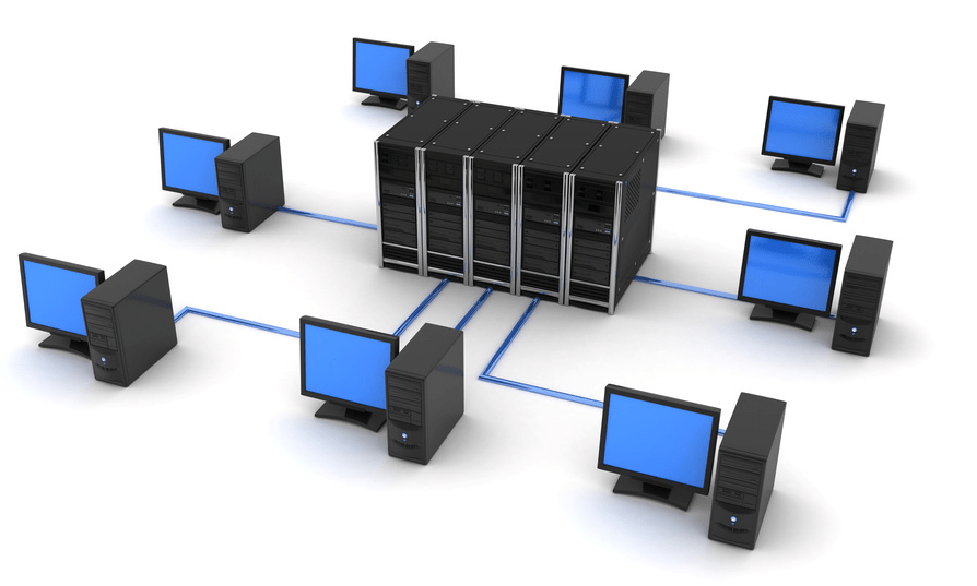
This is the parallel connection of devices to a network to a common source - a server. A hub or concentrator is most often used as a center. All data is transmitted through it. In this way, not only computers, but also printers, faxes and other equipment can operate. In modern enterprises, this is the most frequently used method of organizing activities.

Advantages:
- It's easy to connect another location.
- Performance does not depend on the speed of individual elements, so it remains at a stable high level.
- Just find the problem.
Flaws:
- A malfunction of the central device stops the activities of all users.
- The number of connections is determined by the number of ports on the server device.
- The mesh consumes a lot of cable.
- High cost of equipment.
Stages of LAN software design
This is a multi-stage process that requires the competent participation of many specialists, since the required cable capacity must first be calculated, the configuration of the premises taken into account, and the equipment installed and configured.
Organizational premises planning
The offices of employees and management should be located in accordance with the selected topology. If the star shape suits you, then you should place the main equipment in the room that is the main one and is located in the center. This could be the management office. In the case of bus distribution, the service may be located in the room furthest along the corridor.
Building a local network diagram

The drawing can be made in specialized computer-aided design programs. The products of the ZVSOFT company are ideal - they contain all the basic elements that will be required during construction.
The grid must take into account:
- maximum voltage;
- sequence of occurrences;
- possible interruptions;
- installation efficiency;
- convenient power supply.
The characteristics of the LAN must be selected in accordance with the layout of the organization's premises and the equipment used.
Computer and network device settings
When selecting and purchasing mesh elements, it is important to consider the following factors:
- Compatible with different programs and new technologies.
- Data transfer speed and performance of devices.
- The quantity and quality of cables depends on the selected topology.
- A method for managing network exchanges.
- Protection from interference and failures by winding wires.
- Cost and power of network adapters, transceivers, repeaters, hubs, switches.
Principles of LAN design using computer programs
When drawing up a project, it is important to take into account a large number of nuances. Software from ZWSOFT will help with this. The company develops and sells multifunctional software to automate the work of design engineers. Basic CAD is an analogue of the popular but expensive package from Autodesk - AutoCAD, but surpasses it in ease and convenience of licensing, as well as in a more loyal pricing policy.

Benefits of the program:
- Intuitive, user-friendly interface in black.
- Wide selection of tools.
- Work in two-dimensional and three-dimensional space.
- 3D visualization.
- Integration with files of most popular extensions.
- Organization of LAN elements in the form of blocks.
- Calculation of cable line lengths.
- Visual arrangement of elements and nodes.
- Simultaneous work with graphics and text data.
- Ability to install additional applications.
For ZWCAD - a module that expands the functions of basic CAD in the field of designing multimedia circuits. All drawings are made with automated calculation of local area network cables and their markings.
Advantages:
- automation of selection of switching systems;
- wide library of elements;
- parallel filling of the cable log;
- automatic creation of specifications;
- adding equipment to the library;
- simultaneous work of several users with the database;
- schematic marks for the location of devices and pieces of furniture.
It will help you make a project in three-dimensional form, create it in 3D. Intelligent tools allow you to quickly lay LAN routes to connection points, visually represent the locations of cables, organize intersections of lines, and make cuts of connected equipment and technological furniture (including in dynamic mode). Using the component editor, you can create a library of cabinets, switching devices, cables, clamps, etc., as well as assign characteristics to them, on the basis of which you can later create specifications and cost estimates. Thus, the functions of this software will help to complete the master plan of the organization’s premises with tracing of all LAN lines.
Create a local computer network project in your enterprise together with programs from ZVSOFT.
Let's decide on the starting points: a small company, maybe about 15-50 employees. As a rule, there is no qualified network specialist. And most likely it’s the one “dedicated” to working with the network, the network administrator on staff. Let's agree - your own specialist is still necessary. And he needs to be paid money, and good money at that (what a horror, right? This is news for many directors). In this article (possibly with a continuation) I will try to act as a network administrator for such a small company. So, we build the network ourselves. Why not? There are many arguments against self-dealing, and all of them are true (unless, of course, it is an outright “noodle” from a potential contractor). But, still, you can do it yourself. There are also plenty of arguments in favor. We will not present them here - we believe that we decided to do it ourselves. We will not create newfangled radio, Wi-Fi and other networks, but an inexpensive but high-quality cable network of the traditional wire type for the daily work of the company. However, you must understand that the work must be performed by a specialist (or several).
Introduction
Let's decide on the starting points: a small company, maybe about 15-50 employees. As a rule, there is no qualified network specialist. And most likely it’s the one “dedicated” to working with the network, the network administrator on staff. If there is one, he is a jack of all trades, and is often forced to deal with some “urgent” matter, such as installing Windows or drivers on some computer, instead of working with the network. Together with other "computer scientists" (if there are any). Is the network working? Let the deck pass through the stump, oh well, we’ll get to work a little later (we’ll get to work on it).
Let's agree - your own specialist is still necessary. And he needs to be paid money, and good money at that (what a horror, right? This is news for many directors). In this article (possibly with a continuation) I will try to act as a network administrator for such a small company.
Initial data
So, we build the network ourselves. Why not? There are many arguments against self-dealing, and all of them are true (unless, of course, it is an outright “noodle” from a potential contractor). But, still, you can do it yourself. There are also plenty of arguments in favor. We will not present them here - we believe that we decided to do it ourselves.However, you must understand that the work must be performed by a specialist (or several). You cannot train (“even if inferior, but your own”) and raise your specialist using this method. You can give yours to the person doing the work (we won’t take into account drilling holes in the walls with a hammer drill and attaching cable ducts - any man should be able to do this).
One more factor, let’s add the “pepper” so to speak - our company, in addition to the office, has a store and a warehouse, which are quite remote.
We will not create newfangled radio, Wi-Fi and other networks, but an inexpensive but high-quality cable network of the traditional wire type for the daily work of the company. For work, not for surfing news and/or porn sites from a laptop from a hotel sofa. We may return to these questions in the sequel (not to the hotel and its ilk, of course, but to modern technologies).
Last, and also very important: we count money, but don’t be greedy.
Plan
At the very beginning, you must do one very simple, but very important thing - take a few sheets of paper, a pencil and sit down to draft a business plan. It is very important to more or less clearly “take a pencil” of all the keywords that come to mind from the question “what do I want from the network”. Sketch these positions on the first sheet. The second step is to group them into separate categories. For example, the “services” category. What services do we want to receive from the network, and what quality? What do we need? File-, ftp-, print-, internet service?It would seem that everything is clear, why write, draw? But if you don’t take everything into account, it will get worse later. For example, it turns out that you need to go to the director and/or the accounting department: “Sorry, we bought the wrong piece of hardware here, and not for 100 USD. necessary, but for 500.”
Now, after taking a rest, you can add what you need and throw away the excess. And put all this off for at least a day. Next, the draft can be transferred to the third sheet. With "final" additions and corrections. Why the quotation marks - you yourself understand, this is not the last piece of paper, and far from the last “sketches”.
Services are services, however, the base is SCS, that is, a structured cable system. Let's try not to run too far ahead of the horse.
Usually there are two options - an office “from scratch” and an office “ready”. The first case is bare walls and ceiling, the renovation is ours, and that’s good. The second option is “ready”. Those. - we begin the external laying of the SCS. But let's not start with that, for now.
Electricity
An important stage, because God forbid that not just one or two ordinary computers “fly”, everything can “fly”. Okay, we think that everything is fine with the power network in our office. There is only one important point here - uninterruptible power supplies (UPS). They are necessary. Believe me. A diesel generator is, of course, good, but not necessary in all cases, but sparing money on installing a UPS on every server or communication cabinet is simply stupid. However, we will return to the issue of UPS in due time.SCS and basic active equipment
Structured cabling system (SCS) is one of the cornerstones. The SCS must be properly designed and built. Let's divide the question into points:
* Communication cabinet (with “stuffing”)
* Cable lines
* Subscriber sockets
This is where a floor plan, with employee positions clearly marked, comes in handy. One thing to keep in mind is that it’s a good idea to also mark the power outlets. Next, in order, let's start with the closet.
Communication cabinet: We find a convenient place to install a cabinet with equipment. It is important to find the optimal distance to workstations in order to reduce costs for twisted pair cables, cable channels and other “trifles”. There are many factors: limiting the line length to 100 meters (or rather, 90 meters, according to the classic formula 90+5+5); office layout (in what place is it convenient to place or hang a cabinet, is it convenient to go through walls when pulling cables, will the cooling put pressure on the ears of clients or employees, etc.); in fact, the design of the cabinet (floor-mounted, wall-mounted, its height in U, the amount of equipment that needs to be installed in it, whether there will be a cooling unit).
There are a wide variety of cabinets, you need to carefully look at the prices and quality of the proposed purchase, do not forget to make a reserve of capacity (!) in those same U. The presence of at least one shelf is a must. However, in some places it is quite possible to get by with wall brackets to secure the equipment. But this is already specific. We will assume that for the office we have chosen a 12-14 high cabinet with a glass door. Looking ahead a little, it is necessary to mention what will be installed inside:
Shelf: It will always be useful, even if it is empty (I doubt it) - it can be removed. You should not regret 10-20 dollars when you have to “suddenly” put a device or two in the closet, remember these lines.
Switch: 24 ports are the lower limit of company employees in the office - let there be 10-20 people in the office (and don’t forget about servers and other network equipment). However, if there is a high density of jobs, there will be no problems adding the required number of switches and other related equipment.
Distribution panel (patch panel): 24 ports, everything is the same with a switch. It is to the patch panel that all lines from workstations and servers will be connected.
Panel (block) of power sockets: according to the amount of connected equipment in the cabinet, plus a reserve of 1-2 sockets on the panel. Here we may well be faced with an “ambush” if we have to connect power supplies - there may not be enough (remember that 99.9% of the market is filled with surge protectors with sockets placed tightly and obliquely).
You can install a cheap, simple option (that’s when a shelf comes in handy, but you can also install it on the floor of a cabinet), or you can install a 19” UPS designed for installation in a cabinet.

So, having looked at the products offered on the market, we believe that we have decided on a cabinet: 14-high (14 U). For example, Molex MODBOX II 14U:
Possibility of using a 19-inch 1U fan in a cabinet
. Standard cabinet configuration:
. Lightweight steel profile provides the cabinet with greater rigidity and strength
. Aesthetic glass door with lock
. Door of universal design with the possibility of reversing (left, right)
. 19" frame with depth adjustment
. Grounding of all cabinet elements
. The cable entry holes are equipped with a protective brush to prevent dust from entering the cabinet
Switch. His choice is a more complex matter. I don’t want to consider very cheap switches. There are still more expensive (and very expensive) devices, but you still have to choose from two types: unmanaged and managed.
Let's take a look at the following two devices: ZyXEL Dimension ES-1024 and ES-2024:

It is a cost-effective Fast Ethernet solution and can be used to build highly efficient switched networks. The store-and-forward feature significantly reduces latency on high-speed networks. The switch is designed for workgroups, departments, or backbone computing environments for small and medium-sized enterprises. Due to its large address table and high performance, the switch is an excellent solution for connecting departmental networks to a corporate backbone or connecting network segments.
Specifications:
24-Port Fast Ethernet Switch
. Compliant with IEEE 802.3, 802.3u and 802.3x standards
. RJ-45 Ethernet ports with automatic 10/100 Mbps speed selection
. Automatic detection of crossover cable connections on all RJ-45 10/100 Mbps Ethernet ports
. Supports Back-Pressure-Base flow control on half-duplex ports
. Support Pause-Frame-Base flow control on full duplex ports
. Support for store-and-forward switching
. Supports automatic address detection
. Maximum forwarding speed over a wired network
. Built-in MAC address table (8K MAC address capacity)
. LED indicators for power, LK/ACT and FD/COL

Application of the ES-2024 switch will allow you to unite a group of users and connect them to the corporate network via high-speed lines. Additionally, it will be possible, thanks to the use of iStackingTM technology, to combine a group of switches for network management, regardless of their location.
Specifications:
24 RJ-45 ports with auto 10/100 Ethernet speed and auto crossover cable detection
. 2 10/100/1000 Ethernet ports
. 2 mini-GBIC slots combined with ports
. 8.8 Gbps non-blocking switch bus
. Supports IEEE 802.3u, 802.3ab, 802.3z, 802.3x, 802.1D, 802.1w, 802.1p protocols
. MAC address table 10Kb
. VLAN support: Port-based and 802.1Q
. Ability to limit port speed
. 64 static VLANs and up to 2Kb dynamic VLANs
. MAC address filtering
. Supports ZyXEL iStacking™, up to 8 switches (in the future up to 24) controlled by one IP address
. Control via RS-232 and WEB interface
. Telnet CLI
. SNMP V2c(RFC 1213, 1493, 1643, 1757, 2647)
. IP management: static IP or DHCP client
. Firmware update via FTP
. Updating and saving system configuration
. Standard 19" rack mount
As you can see, there is a difference, and a very serious one. There is a difference in price - approximately 100 and 450 dollars. But, if the first switch is a decent, but “dumb” box, then the second is in some sense intelligent, with much greater functionality and controllability, with potentially strong sides. We choose the second option. We want to build a good network, right?
By the way, right now is the time to ask the question, why are we actually building a “hundredth” network? Nowadays, every second computer has not just a gigabit network interface, but two gigabit ones?
This is the case where you can safely save. The fact is that a 100-megabit network is more than enough for office work. If, moreover, the switch is decent! Yes, and on the two gigabit interfaces of the selected switch, we can safely “plant”, for example, two servers. This is just for their benefit, the servers.
Of course, you can take something like the ZyXEL GS-2024 and put everyone on a gigabit channel, but this is just a case of unreasonable spending of money, and for that kind of money we can buy the entire cabinet with a more complete set.

Patch panel. This is also a case where you shouldn’t save much. We choose a panel like Molex 19" 24xRJ45, KATT, 568B, UTP, PowerCat 5e, 1U.
Category 5e compliant. The compensation system is implemented directly on the printed circuit board. The use of KATT type connectors speeds up and simplifies cable installation. Dedicated space for channel marking. The panel is powder coated. All necessary fastening and marking elements are supplied in the kit.
There are many options here, as already mentioned, you can install any cheap one, you can get it more expensive, you can have a 19” rack version - it will be absolutely beautiful. Who doesn't know APC? For example, you can look at this UPS:

APC Smart-UPS SC 1500VA 230V - 2U Rackmount/Tower
Or like this:

Without delving into the specifications, we note that many devices are equipped upon request with guides for installing a UPS in a 19" rack. It is also possible to equip, if desired, an SNMP module for monitoring and managing the UPS over a computer network. Of course, this will cost money, but may turn out to be very convenient. Let's choose IPPON. It should be noted that models 1500, 2000 and 3000 can be equipped with SNMP support, but 750 and 1000 cannot.
Power socket block:

Without any special comments - maybe you can find something cheaper and simpler. But a dozen “strangled raccoons” won’t make a difference.
The only thing left to remember is to decide whether a fan unit is needed in the cabinet? An expensive pleasure, especially when paired with a thermostat unit. However, let’s relate this to the specifics of the location/office.

We’ve more or less sorted out the closet, all that remains are all sorts of “little things”, without taking into account which there will be annoying delays later:
* Screws with nuts for mounting equipment in the cabinet;
* Nylon non-opening ties for laying and fastening cables (packs of 100 pieces, 100, 150, 200 mm long);
* Cable markings (adhesive sheets with a protective layer).
In fact, we got to the SCS itself. A very important “detail” is the cable that will be used to wire the SCS. Yes, again the call not to save. A good twisted pair cable is a good investment. We take Molex, unshielded UTP PowerCat 5e cable.

The cable is the core element of the PowerCat product line. The line is designed for use in high-speed telecommunications networks (for example GigaEthernet 1000Base-T).
We will, of course, come to the subscriber sockets, but what next? Next - buy the required number of patch cords to connect workstations. Naturally, you need to think about the length, look at the mentioned office plan. But that is not all. You also need a strainded cable (regular - solid). This is a special twisted pair, “soft”, from which patch cords are made. After all, sooner or later you will definitely need a patch cord of a greater length than is available ready-made at hand (if there are any left at all by that time). In addition, you can (or necessary - as you wish) it will be to make short - 30-50 cm, patch cords for cross-connecting SCS lines and active equipment in the cabinet itself. Therefore, we “take a pencil” for a couple more packages of RJ45 connectors, in common parlance - “chips.” And packaging of rubber caps for them. It is better to take the caps soft and with a slot for the “chip” retainer, and not with a “pimple” for the retainer.
We have almost reached the network interfaces on user computers, but subscriber sockets are still needed. Is anyone against such a wonderful thing as Molex OFFICE BLOCK 2xRJ45? ;-)

Category 5e compliant. The modules are designed for high-speed telecommunication networks. Possibility of cable entry from the sides, top or rear. As standard, the modules are equipped with dust curtains. Convenient channel marking. The built-in magnet simplifies the installation of modules on metal surfaces. Possibility of fastening with screws. Cable fastening inside the module without cable clamps. Free choice of connection sequence (568A/B). "KATT" type connector for easy installation. The kit includes mounting elements. .
Here you need to decide on the quantity. After all, there are single options. Let's take the office plan again. There is another important point in determining the installation locations for sockets - it is advisable to add one or two additional SCS lines to each office. One - just “just in case”. What if the layout in the office changes a little or someone needs to connect a laptop? The second is a good idea to have for a print server, for organizing network printing. It’s very nice to have one or two network printers per office or office that work without the problems and whims of the owner (or Windows).
Do you think that's it? No. Another factor that is present in any office has been forgotten - telephony. It’s very good to think about this: if telephones must be connected to some workplaces, then why not make the wiring in a common SCS? After all, the issue can be solved simply: throw a line or two to the necessary places, install an RJ-12 socket next to the RJ-45, it can even be in one case (block). In a socket - DECT, for example, with several handsets, and in a cabinet we draw a line (lines) from the PBX - they can be placed on sockets carefully glued with Velcro inside and on the sides. Lines from workplaces are on them.
It seems like it’s time to take on the cable duct and dowel-nails? Yes. It is time. But this is already clear to any handy man; let’s not dwell on this for long. You just need to take into account the number of lines being laid in the cable channel. And, of course, a small supply is needed. It is very good if the office has a suspended ceiling; the lines can be stretched behind it directly to the workplace and lowered in a cable channel along the wall. When drawing lines, it’s a good idea to label them (as well as sockets in the future). The simplest method is the first socket to the left of the door - No. 1, then in a circle.
Having stretched the lines, you can start splitting the patch panel and sockets. Needless to say, this work requires precision and skill. It is at this moment that marking the lines will be useful to us - if all the lines are split in order, then in the further operation of the SCS it will be possible to practically do without an installation map (layout), something like this:
Socket
However, this card is still necessary in the future. It will definitely come in handy.
When laying cables, you need to follow a few simple rules (just simple, we won’t go deep into standards and other ISOs):
* Do not bend, rub or step on the cable. Cable bending is allowed: during installation - 8, and during operation - 4 radii of the cable itself;
* Do not lay lines next to power lines: if there is a need to lay them in parallel - at a distance of at least 20 cm;
* It is allowed to cross power lines at right angles;
* Testing with a cable tester is required.
Separately about the last point. Remember the joke about the Japanese supply of something there? “Dear customers! We don’t know why you need this, but we still decided to put one defective chip in the boxes for every ten thousand, according to your requirements.” Yes, you can just split it and forget it. An experienced installer makes no mistakes. However, a truly experienced installer will definitely check not only the line layout, but also the quality.
Now we have reached the most interesting moment. If we check small things with a simple and cheap tester, then testing and certifying the lines - no, it won’t work:

Which exit? I really don’t want to leave the issue of line quality unresolved. There are three options. The first is to buy a good tester, for example:
But, alas, we really feel sorry for the $6,000, even for such a wonderful and necessary device.

It is a compact, portable tool used to qualify, test and troubleshoot coaxial and twisted pair cables in local area networks. The tester is recommended by leading manufacturers of information cable systems for testing for certification of systems up to Class E inclusive. The high level of reliability, convenience and accuracy of the device ensured it one of the first places among products of this class. For fast and high-quality testing of cable connections in an extended frequency range up to 350 MHz, digital pulse signal processing technologies are used.
The second option is to invite a friend of the admin or installer who has this or a similar device. Of course, first buy a case of good beer. Half an hour of work, plus a beer evening in the pleasant company of a friend.
The third option is to officially invite specialists from any company that provides such services. And pay for these services. This is not so much, especially if you do not require a certificate on paper.
Remote workstations
Having “finished” (quotes because we must first plan everything and make the necessary purchases and negotiations) with the work at the main office, we remember the warehouse and store.
Now (in these notes) we will consider not a “sophisticated” solution like VPN, but the simplest one - organizing the connection of computer networks with subnets (workstations with a network) via a dedicated line. Effective, cheap and cheerful. By the way, dedicated telephones, of course, should be placed in a closet and connected to sockets, just like telephones.

If the distance and, accordingly, the resistance of the dedicated line is small, you can try installing a pair of “bridges”, for example, from the already mentioned company ZyXEL Prestige 841C and ZyXEL Prestige 841. Model “C” is a “master”, so this device is best installed at the head office. These are inexpensive devices that work using VDSL technology, but they provide the necessary results for our task. What ZyXEL says:
Depending on the type and condition of the cable, as well as the distance, the Prestige 841 paired with the Prestige 841C provides the following data exchange speed:
Toward the subscriber - ranging from 4.17 to 18.75 Mbit/s
. in the direction from the subscriber - from 1.56 to 16.67 Mbit/s
. the total line capacity can reach 35 Mbit/s
Specifications:
VDSL Ethernet bridge
. Connection of local networks at a speed of 15 Mbit/s up to 1.5 km
. Plug&Play, transparent for all protocols
. Work in pairs
. Desktop version
. Non-volatile memory (Flash ROM)
. Size: 181 x 128 x 30 mm
This option will give 18 Mb in each direction, ideally, of course. This is VDSL.
There is one more benefit to using the Prestige 841. These devices have a built-in splitter, and we can get “free” telephony from a remote location. It is enough to plug the remote workplace telephone into the “phone” connector on one side, and connect an office mini-PBX on the other side.
If the VDSL bridges do not “stretch” the line, you need to look at other devices, xDSL. For example - something from the 79x series ZyXEL, SHDSL.

Optimization of the hardware and the use of advanced technologies made it possible not only to reduce the dimensions of the device, but also to reduce the cost and improve the functional characteristics. provide a symmetrical connection at speeds up to 2.3 Mbit/s and can operate on a dedicated 2-wire line both in point-to-point mode and as a client of an Internet provider hub.
Specifications:
. SHDSL router
. Supports G.991.2 at speeds up to 2.3 Mbps symmetrically
. Connecting networks or accessing the Internet over long distances
. Encapsulation PPPoA, PPPoE, RFC-1483
. TCP/IP routing, Full NAT, packet filtering
. Support IP Policy Routing, UPnP, connection redundancy
. Management via console, Telnet, Web, SNMP
The ideal speed is 2.3Mb over two wires. If you “charge” 4 wires, the speed will be correspondingly higher. However, these devices will cost a large amount - $400-500 per pair. In any case, roughly speaking, the worse the quality of the line, the lower the speed and the higher the costs. However, we will postpone setting up (tuning) devices for the future; this is a separate conversation, especially since in the case of VDSL 841 this does not make too much sense at all. xDSL devices should be placed on a shelf in the closet. I told you it wouldn't be empty.
Internet connection

ZyXEL Prestige-660
A modern office is unthinkable without the Internet. To connect we can use ADSL technology, for example - ZyXEL Prestige 660.
As ZyXEL describes this device:
Modem P-660R belongs to the fourth generation of ADSL modems and combines in one device the functionality necessary to connect an existing office or home network to the Internet: ADSL2+ modem, router and firewall. The modem will provide your office with a constant Internet connection that is fast and secure. Installation and maintenance of the P-660R modem is simple and will not cause any problems even for untrained users.
Main advantages of ZyXEL Prestige 660:
* High-speed Internet - up to 24 Mbit/s
* Reliable connection on problem lines
* Free phone
* Permanent connection
* Does not require driver installation
* Works with W
MINISTRY OF SCIENCE AND PROFESSIONAL EDUCATION
REPUBLIC OF SAKHA (YAKUTIA)
STATE EDUCATIONAL INSTITUTION
SECONDARY VOCATIONAL EDUCATION
NERYUNGRI HUMANITIES COLLEGE
Subject cycle commission
"Mathematical disciplines and information technologies"
COURSE WORK
Organization of a local computer network in an enterprise
Norvaishas Sergey Evgenievich
4th year student
Full-time form of education
Specialty: 230105.51
"Software
computer technology and automated systems"
Head: Khamrilova L.A.
Date of course work defense:
"____"_______________2010
Grade: " "
Neryungri
Introduction 5
1.1. Purpose of packages and their structure 7
1.2. Exchange management methods 13
1.3. Control of exchange in a network with star 15 topology
Chapter 2. Network construction technology 18
2.1. Review and analysis of possible technologies to solve the problem 18
Chapter 3. Design of an enterprise-scale network of the State Educational Institution of Secondary Professional Education "Omsk College of Trade, Economics and Service" 22
3.1.Profile of the enterprise GOU SPO OKTEiS 22
3.2.Selection of network equipment 23
3.3. Brief description of the network equipment used 24
3.4.Selecting network software 25
3.4.1. Operating modes: 30
3.4.2.Installation and configuration 33
3.5.Diagrams of the physical layout of premises OKTEiS 35
3.6. General diagram of the OKTEiS network 37
3.7. Theoretical and calculation part 39
Conclusion 41
List of references 43
Introduction
If in one room, building or complex of nearby buildings there are several computers, the users of which must jointly solve some problems, exchange data or use common data, then it is advisable to combine these computers into a local network.
A local network is a group of several computers connected by cables (sometimes also telephone lines or radio channels) used to transfer information between computers. To connect computers into a local network, you need network equipment and software.
The purpose of all computer networks can be expressed in two words: sharing (or sharing). First of all, we mean shared access to data. People working on the same project must constantly use data created by colleagues. Thanks to a local network, different people can work on the same project not in turn, but simultaneously.
A local network provides the opportunity to share equipment. It is often cheaper to create a local network and install one printer for the entire department than to purchase a printer for each workstation. A network file server allows for shared access to programs.
Hardware, programs and data are combined under one term: resources. We can assume that the main purpose of a local network is access to resources.
The local network also has an administrative function. Monitoring the progress of projects online is easier than dealing with multiple offline computers. If there is a local network in the classroom, then it also performs an administrative function, allowing you to control the progress of students' classes.
To communicate with external (peripheral) devices, the computer has ports through which it is capable of transmitting and receiving information. It is not difficult to guess that if two or more computers are connected through these ports, they will be able to exchange information with each other. In this case, they form a computer network. If computers are located close to each other, use a common set of network equipment and are controlled by the same software package, then such a computer network is called local. The simplest local networks are used to serve workgroups. A work group is a group of people working on the same project (for example, publishing the same magazine or developing the same aircraft) or simply employees of the same department.
The purpose of the course work is to design a local computer network (LAN) for the State Educational Institution of Secondary Professional Education "Omsk College of Trade, Economics and Service" (OKTEiS).
To achieve the goal, the following tasks are set:
analyze methods of managing exchanges on the network;
review and analyze possible network construction technologies;
select network equipment and software for the LAN;
design a general college LAN scheme;
Chapter 1. Packets, protocols and communication control methods
Purpose of packages and their structure
Information in local networks, as a rule, is transmitted in separate portions, pieces, called packets. Moreover, the maximum length of these packets is strictly limited (usually several kilobytes). The packet length is also limited from below (usually by several tens of bytes). The choice of packet transmission involves several important considerations.
The local network, as already noted, must provide high-quality communication to all network subscribers. The most important parameter is the so-called network access time, which is defined as the time interval between the moment the subscriber is ready to transmit (when he has something to transmit) and the moment this transmission begins. This is the time the subscriber waits for the start of his transmission. Naturally, it should not be too large, otherwise the value of the real, integral speed of information transfer between applications will greatly decrease even with high-speed communication.
Waiting for the start of transmission is due to the fact that several transmissions cannot occur simultaneously in the network (at least with bus and ring topologies). There is always only one transmitter and one receiver (less often, several receivers). Otherwise, information from different transmitters is mixed and distorted. In this regard, subscribers transmit their information one by one. And each subscriber, before starting the transmission, must wait for his turn. This time of waiting for your turn is the access time.
If all the required information were transmitted by some subscriber immediately, continuously, without division into packets, this would lead to an exclusive takeover of the network by this subscriber for quite a long time. All other subscribers would have to wait for the transfer of all information to complete, which in some cases could take tens of seconds or even minutes (for example, when copying the contents of an entire hard drive). In order to equalize the rights of all subscribers, as well as to make the network access time and the integral information transfer rate approximately the same for all of them, packets of limited length are used.
Each packet, in addition to the actual data that needs to be transmitted, must contain a certain amount of service information. First of all, this is address information, which determines from whom and to whom a given packet is transmitted.
Thus, the process of information exchange in the network is an alternation of packets, each of which contains information transmitted from subscriber to subscriber.
Figure 1. Transfer of packets in a network between two subscribers.
In a particular case (Fig. 1), all these packets can be transmitted by one subscriber (when other subscribers do not want to transmit). But usually the network alternates between packets sent by different subscribers (Figure 2).

Figure 2. Transfer of packets in a network between several subscribers.
The structure and size of a packet in each network are strictly determined by the standard for a given network and are associated, first of all, with the hardware features of a given network, the selected topology and the type of information transmission medium. In addition, these parameters depend on the protocol used (the order of information exchange).
But there are some general principles for forming the structure of a packet that take into account the characteristic features of information exchange over any local networks.
Most often, the package contains the following main fields or parts (Figure 3).

Figure 3. Typical package structure
A starting bit pattern or preamble that provides preliminary configuration of the adapter or other network device hardware to receive and process the packet. This field may be completely absent or reduced to a single start bit.
The network address (identifier) of the receiving subscriber, that is, an individual or group number assigned to each receiving subscriber on the network. This address allows the receiver to recognize a packet addressed to him personally, to a group to which he is a member, or to all network subscribers simultaneously (in case of wide broadcasting).
Network address (identifier) of the transmitting subscriber, that is, an individual number assigned to each transmitting subscriber. This address informs the receiving subscriber where the packet came from. Including the transmitter address in the packet is necessary in the case when one receiver can alternately receive packets from different transmitters.
Service information that can indicate the type of packet, its number, size, format, route of its delivery, what the receiver needs to do with it, etc.
Data (data field) is the information for which the packet is used to transmit. Unlike all other fields of the packet, the data field has a variable length, which, in fact, determines the total length of the packet. There are special control packages that do not have a data field. They can be thought of as network commands. Packets that include a data field are called information packets. Control packets can perform the function of starting and ending a communication session, confirming the receipt of an information packet, requesting an information packet, etc.
The packet checksum is a numeric code generated by the transmitter according to certain rules and containing information about the entire packet in a collapsed form. The receiver, repeating the calculations made by the transmitter with the received packet, compares their result with the checksum and makes a conclusion about the correctness or error of the packet transmission. If the packet is erroneous, the receiver requests that it be retransmitted. Typically a cyclic checksum (CRC) is used.
The stop combination serves to inform the receiving subscriber's equipment about the end of the packet and ensures that the receiver's equipment exits the receiving state. This field may be absent if a self-synchronizing code is used to determine when the packet has completed transmission.