Is there a radio that works without batteries?
Exists! Detector radio receiver. Such a receiver receives power from radio waves. Its circuit is very simple and will take about 40 minutes to assemble.
Pros of the detector receiver:
- Works without batteries (radio without batteries).
- The parts for its manufacture are very easy to obtain.
- Easy to assemble.
But there are also disadvantages:
- Only one local station will have good reception; the rest will simply be drowned out by it.
- Low power. You won’t be able to connect good speakers; the power is only enough for headphones or a speaker from an old rotary telephone.
But for a summer residence, a detector radio is a good solution.
You will need:
- Capacitor 1000 – 2000 Pf;
- Fixed capacitor 190 – 500 Pf;
- Diode (any);
- Cylinder with a diameter of 10 cm;
- Newspaper;
- Copper wire with a diameter of 1 – 0.1 mm;
- A speaker from an old rotary telephone or headphones (high-impedance);
- The metal pin is 30 cm long.
Detector radio receiver circuit (Oganov circuit)
So, let's begin. Let's make grounding. We drive a metal pin into the ground on the shady side of the house (the ground there is always wet) after connecting it to the wire. The better you ground, the better radio reception will be. We run a grounding wire into the house.
Next we make the antenna. It can be made from copper wire. The length depends on what result you want to get. The antenna is 10 m long and will only receive one station, but it will be good and loud. An antenna 1 - 3 m long will receive several radio stations, but with poor quality.
The antenna is done, now it’s the coil’s turn. The coil consists of two equal parts. To receive medium waves, each part contains 20 turns, and to receive long waves, 60 turns. So, we have decided on the wavelength, now we wind the coil. Take a cylinder with a diameter of 10 cm, tape it around it with newspaper. We wind the second layer of newspaper loosely onto the first one, so that after winding the wire, the coil can be easily removed.
We wind the wire turn to turn, leaving 5 cm of wire between the two parts (also 5 cm, leave at the output and input of the coil). Reeled in? Now we wrap it in two layers, along the turns with electrical tape, then remove the coil from the cylinder and wrap it across it as well.
Now let's start assembling the radio without batteries.
The above diagram of a detector radio receiver can be simplified.
We solder all the parts to each other.
Setup. This is done by moving one part of the coil relative to the other. You can also replace C1 with several variable capacitors. By adjusting them, you will achieve maximum signal quality.
If the signal quality is very poor, you can try making a coil of thicker wire.
You will need just one chip to build a simple and complete FM receiver that is capable of receiving radio stations in the range of 75-120 MHz. The FM receiver contains a minimum of parts, and its configuration, after assembly, is reduced to a minimum. It also has good sensitivity for receiving VHF FM radio stations.
All this thanks to the Philips TDA7000 microcircuit, which can be bought without problems on our favorite Ali Express.
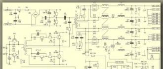
Receiver circuit
Here is the receiver circuit itself. Two more microcircuits were added to it, so that in the end it turned out to be a completely finished device. Let's start looking at the diagram from right to left. The now classic low-frequency amplifier for a small dynamic head is assembled using the LM386 chip. Here, I think, everything is clear. A variable resistor adjusts the volume of the receiver. Next, a 7805 stabilizer is added above, which converts and stabilizes the supply voltage to 5 V. Which is needed to power the microcircuit of the receiver itself. And finally, the receiver itself is built on the TDA7000. Both coils contain 4.5 turns of PEV-2 0.5 wire with a winding diameter of 5 mm. The second coil is wound on a frame with a ferrite trimmer. The receiver is tuned to the frequency using a variable resistor. The voltage from which goes to the varicap, which in turn changes its capacitance.If desired, varicap and electronic control can be abandoned. And the frequency can be tuned either with a tuning core or with a variable capacitor.
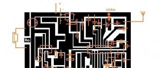
FM Receiver Board
I drew the circuit board for the receiver in such a way as not to drill holes in it, but to solder everything from the top, as with SMD components.Placing elements on the board

Used classic LUT technology to produce the board.


I printed it, heated it with an iron, etched it and washed off the toner.


Soldered all the elements.

Receiver setup
After turning it on, if everything is assembled correctly, you should hear hissing in the dynamic head. This means that everything is working fine for now. The whole setup comes down to setting up the circuit and selecting the range for reception. I make adjustments by rotating the coil core. Once the reception range is configured, channels in it can be searched for using a variable resistor.Conclusion
The microcircuit has good sensitivity, and a half-meter piece of wire, instead of an antenna, can pick up a large number of radio stations. The sound is clear, without distortion. This circuit can be used in a simple radio station, instead of a receiver on a supergenerative detector.I tried to make this homemade VHF receiver in a “retro” style. Front End from car radio. KSE marking. Next, the IF unit on the KIA 6040, the ULF on the tda2006, the 3GD-40 speaker, in front of which there is a 4-5 kHz notch, I don’t know exactly, I selected it by ear.
Radio receiver circuit
I don’t know how to do digital tuning, so it will just be a variable resistor; for this VHF unit, 4.6 volts is enough to completely cover 87-108 MHz. Initially I wanted to insert an ULF on P213 transistors, since I had assembled and rebuilt the “retro” one, but it turned out to be too bulky, so I decided not to show off.

Well, a surge filter is installed, of course it won’t hurt.

There was no suitable dial indicator, or rather there was one, but it was a pity to install it - there were only 2 left, so I decided to remake one of the unnecessary M476s (as in Ocean-209) - I straightened the needle and made a scale.

Illumination - LED strip. The vernier is assembled from parts of various radios, from tube radios to China. The entire scale with the mechanism is removed, its body is glued together from many wooden parts, the rigidity is given by the textolite on which the scale is glued and all this is pulled to the receiver body, simultaneously additionally pressing the front panels (those with a mesh), which are also removed if desired.

Scale under glass. The tuning knobs are from some radio from a junkyard, tinted.

Overall, a flight of fancy. I have long wanted to try out the curvature of my hands by building something similar. And here there was absolutely nothing to do, and scraps of plywood from the renovation remained, and the mesh turned up.

Since ready-made vintage cases in good condition are already difficult to get, I made a homemade replica; in our outback, all the vintage rotted away in the garages long ago. Inspired by this photo:

Discuss the article HOMEMADE RADIO IN RETRO STYLE
Construction of the building
To make the body, several boards were cut from a sheet of treated fiberboard 3mm thick with the following dimensions:
— front panel measuring 210mm by 160mm;
- two side walls measuring 154mm by 130mm;
— upper and lower walls measuring 210mm by 130mm;
— rear wall measuring 214mm by 154mm;
— boards for attaching the receiver scale measuring 200mm by 150mm and 200mm by 100mm.

The box is glued together using wooden blocks using PVA glue. After the glue has completely dried, the edges and corners of the box are sanded to a semicircular state. Irregularities and flaws are puttied. The walls of the box are sanded and the edges and corners are sanded again. If necessary, putty again and sand the box until a smooth surface is obtained. We cut out the scale window marked on the front panel with a finishing jigsaw file. Using an electric drill, holes were drilled for the volume control, tuning knob and range switching. We also grind the edges of the resulting hole. We cover the finished box with primer (automotive primer in aerosol packaging) in several layers until completely dry and smooth out the unevenness with emery cloth. We also paint the receiver box with automotive enamel. We cut out the scale window glass from thin plexiglass and carefully glue it to the inside of the front panel. Finally, we try on the back wall and install the necessary connectors on it. We attach plastic legs to the bottom using double tape. Operating experience has shown that for reliability, the legs must either be firmly glued or fastened with screws to the bottom.
Holes for handlesChassis manufacturing
The photographs show the third chassis option. The plate for fastening the scale is modified to be placed in the internal volume of the box. After completion, the necessary holes for the controls are marked and made on the board. The chassis is assembled using four wooden blocks with a cross-section of 25 mm by 10 mm. The bars secure the back wall of the box and the scale mounting panel. Posting nails and glue are used for fastening. A horizontal chassis panel with pre-made cutouts for placing a variable capacitor, volume control and holes for installing an output transformer is glued to the lower bars and walls of the chassis.
Electrical circuit of the radio receiver


prototyping did not work for me. During the debugging process, I abandoned the reflex circuit. With one HF transistor and a ULF circuit repeated as in the original, the receiver started working 10 km from the transmitting center. Experiments with powering the receiver with a low voltage, like an earth battery (0.5 Volts), showed that the amplifiers were insufficiently powerful for loudspeaker reception. It was decided to increase the voltage to 0.8-2.0 Volts. The result was positive. This receiver circuit was soldered and, in a two-band version, installed at a dacha 150 km from the transmitting center. With a connected external stationary antenna 12 meters long, the receiver installed on the veranda completely sounded the room. But when the air temperature dropped with the onset of autumn and frost, the receiver went into self-excitation mode, which forced the device to be adjusted depending on the air temperature in the room. I had to study the theory and make changes to the scheme. Now the receiver worked stably down to a temperature of -15C. The price for stable operation is a reduction in efficiency by almost half, due to an increase in the quiescent currents of transistors. Due to the lack of constant broadcasting, I abandoned the DV band. This single-band version of the circuit is shown in the photograph.
Radio installation
The homemade receiver circuit board is made to match the original circuit and has already been modified in the field to prevent self-excitation. The board is installed on the chassis using hot melt adhesive. To shield the L3 inductor, an aluminum shield connected to a common wire is used. The magnetic antenna in the first versions of the chassis was installed in the upper part of the receiver. But periodically, metal objects and cell phones were placed on the receiver, which disrupted the operation of the device, so I placed the magnetic antenna in the basement of the chassis, simply gluing it to the panel. The KPI with an air dielectric is installed using screws on the scale panel, and the volume control is also fixed there. The output transformer is used ready-made from a tube tape recorder; I assume that any transformer from a Chinese power supply will be suitable for replacement. There is no power switch on the receiver. Volume control is required. At night and with “fresh batteries,” the receiver begins to sound loud, but due to the primitive design of the ULF, distortion begins during playback, which is eliminated by lowering the volume. The receiver scale was made spontaneously. The appearance of the scale was compiled using the VISIO program, followed by converting the image into a negative form. The finished scale was printed on thick paper using a laser printer. The scale must be printed on thick paper; if there is a change in temperature and humidity, the office paper will go in waves and will not restore its previous appearance. The scale is completely glued to the panel. Copper winding wire is used as an arrow. In my version, this is a beautiful winding wire from a burnt-out Chinese transformer. The arrow is fixed on the axis with glue. The tuning knobs are made from soda caps. The handle of the required diameter is simply glued to the lid using hot glue.
Board with elements Container with batteries
As mentioned above, the “earthen” power option did not work. It was decided to use dead “A” and “AA” format batteries as alternative sources. The household constantly accumulates dead batteries from flashlights and various gadgets. Dead batteries with a voltage below one volt became power sources. The first version of the receiver worked for 8 months on one “A” format battery from September to May. A container is specially glued to the back wall for power supply from AA batteries. Low current consumption requires powering the receiver from solar panels of garden lights, but for now this issue is irrelevant due to the abundance of “AA” format power supplies. The organization of power supply with waste batteries led to the name “Recycler-1”.
Loudspeaker of a homemade radio receiver
I do not advocate using the loudspeaker shown in the photograph. But it is this box from the distant 70s that gives maximum volume from weak signals. Of course, other speakers will do, but the rule here is that the bigger the better.
Bottom line
I would like to say that the assembled receiver, having low sensitivity, is not affected by radio interference from TVs and switching power supplies, and the quality of sound reproduction differs from industrial AM receivers cleanliness and saturation. During any power failures, the receiver remains the only source for listening to programs. Of course, the receiver circuit is primitive, there are circuits of better devices with economical power supply, but this homemade receiver works and copes with its “responsibilities”. Spent batteries are properly burned out. The receiver scale is made with humor and gags - for some reason no one notices this!
Final video
Despite the abundance of all kinds of mobile gadgets and larger equipment, many with interest and genuine passion strive to make something with their own hands. And this is not surprising, because only new knowledge, work and ingenuity make us live and be on a constant path to self-development. This article is dedicated to those who are passionate about electronics and technology. Let's talk about how to make a radio receiver yourself. We will talk about the rare “Komsomolets” model, popular in Soviet times.
What do you need to prepare for work?
To make a radio receiver with your own hands, you need to find:
- An ordinary spool of thread.
- PEL winding wire.
- Wave catcher (D2, D9).
- Head electromagnetic telephones.
- Capacitors with a constant capacitance value.
- Clamps with plug-type sockets.
Now the immediate procedure is how to make a radio receiver with your own hands.
Frame base:
- We use a spool of thread as a frame base.
- Wind the winding conductor (450 turns) onto the coil, making taps every 80 turns.
- Make bends by twisting the wire into loops.
- Clean the taps and ends of the prepared coil.
Important! Spending a lot of time at the dacha during the summer season, you don’t want to completely renounce civilization. To keep abreast of the latest news and events, to be able to relax while watching your favorite programs, it is not at all necessary to spend money on purchasing special equipment. Find out which one is suitable for any type of TV.
How to make a radio with your own hands - assembling the receiver:
- Connect one of the detector contacts to the beginning of the wound solenoid.
- Connect one of the headphone contact legs to the coil end.
- Using a separate piece of wire, connect the leads of the phone and the wave trap.
- Connect the wire - this will be the antenna - to the wire that goes from the detector to the solenoid.
- Strip the end of the antenna from the layer of insulating material.

Grounding
How to make a radio at home - we figured it out. Now screw the ground cable to the conductor connecting the headphone and the end of the solenoid. Now this conductor will be grounded. It is necessary so that you can experiment by switching between the solenoid terminals when setting up the receiver.
Settings
After you have managed to assemble the radio, you still need to take one important step - set it up. To do this, put your phones to your ears and listen for noise. If there is no noise, you need to tune the device to a radio wave. The essence of the adjustment is to change the number of turns in the antenna circuit.
Important! The detector radio receiver is capable of receiving medium and long radio waves. You can also work on improving it so that the device receives waves from remote stations.
How does a detector radio work?
An alternating current is supplied from the antenna, which converts the detector. Next, information is transmitted to headphones in the form of sound waves. Tuning to a particular radio station is done by rotating the knob. The antenna helps to receive signals from powerful points located nearby.
Important! Undoubtedly, low power is a design flaw. But there is an advantage: such a device works without a power source. That's why it's a detector. If you decide not to waste time on assembling the device yourself, you may find it useful.
Video material
As you can see, for someone who is really interested in assembling various electrical appliances, it will be very exciting to assemble a radio with your own hands. Moreover, the operating procedure is very simple and does not require complex actions.