Let's decide on the starting points: a small company, maybe about 15-50 employees. As a rule, there is no qualified network specialist. And most likely it’s the one “dedicated” to working with the network, the network administrator on staff. Let's agree - your own specialist is still necessary. And he needs to be paid money, and good money at that (what a horror, right? This is news for many directors). In this article (possibly with a continuation) I will try to act as a network administrator for such a small company. So, we build the network ourselves. Why not? There are many arguments against self-dealing, and all of them are true (unless, of course, it is an outright “noodle” from a potential contractor). But, still, you can do it yourself. There are also plenty of arguments in favor. We will not present them here - we believe that we decided to do it ourselves. We will not create newfangled radio, Wi-Fi and other networks, but an inexpensive but high-quality cable network of the traditional wire type for the daily work of the company. However, you must understand that the work must be performed by a specialist (or several).
Introduction
Let's decide on the starting points: a small company, maybe about 15-50 employees. As a rule, there is no qualified network specialist. And most likely it’s the one “dedicated” to working with the network, the network administrator on staff. If there is one, he is a jack of all trades, and is often forced to deal with some “urgent” matter, such as installing Windows or drivers on some computer, instead of working with the network. Together with other "computer scientists" (if there are any). Is the network working? Let the deck pass through the stump, oh well, we’ll get to work a little later (we’ll get to work on it).
Let's agree - your own specialist is still necessary. And he needs to be paid money, and good money at that (what a horror, right? This is news for many directors). In this article (possibly with a continuation) I will try to act as a network administrator for such a small company.
Initial data
So, we build the network ourselves. Why not? There are many arguments against self-dealing, and all of them are true (unless, of course, it is an outright “noodle” from a potential contractor). But, still, you can do it yourself. There are also plenty of arguments in favor. We will not present them here - we believe that we decided to do it ourselves.However, you must understand that the work must be performed by a specialist (or several). You cannot train (“even if inferior, but your own”) and raise your specialist using this method. You can give yours to the person doing the work (we won’t take into account drilling holes in the walls with a hammer drill and attaching cable ducts - any man should be able to do this).
One more factor, let’s add the “pepper” so to speak - our company, in addition to the office, has a store and a warehouse, which are quite remote.
We will not create newfangled radio, Wi-Fi and other networks, but an inexpensive but high-quality cable network of the traditional wire type for the daily work of the company. For work, not for surfing news and/or porn sites from a laptop from a hotel sofa. We may return to these questions in the sequel (not to the hotel and its ilk, of course, but to modern technologies).
Last, and also very important: we count money, but don’t be greedy.
Plan
At the very beginning, you must do one very simple, but very important thing - take a few sheets of paper, a pencil and sit down to draft a business plan. It is very important to more or less clearly “take a pencil” of all the keywords that come to mind from the question “what do I want from the network”. Sketch these positions on the first sheet. The second step is to group them into separate categories. For example, the “services” category. What services do we want to receive from the network, and what quality? What do we need? File-, ftp-, print-, internet service?It would seem that everything is clear, why write, draw? But if you don’t take everything into account, it will get worse later. For example, it turns out that you need to go to the director and/or the accounting department: “Sorry, we bought the wrong piece of hardware here, and not for 100 USD. necessary, but for 500.”
Now, after taking a rest, you can add what you need and throw away the excess. And put all this off for at least a day. Next, the draft can be transferred to the third sheet. With "final" additions and corrections. Why the quotation marks - you yourself understand, this is not the last piece of paper, and far from the last “sketches”.
Services are services, however, the base is SCS, that is, a structured cable system. Let's try not to run too far ahead of the horse.
Usually there are two options - an office “from scratch” and an office “ready”. The first case is bare walls and ceiling, the renovation is ours, and that’s good. The second option is “ready”. Those. - we begin the external laying of the SCS. But let's not start with that, for now.
Electricity
An important stage, because God forbid that not just one or two ordinary computers “fly”, everything can “fly”. Okay, we think that everything is fine with the power network in our office. There is only one important point here - uninterruptible power supplies (UPS). They are necessary. Believe me. A diesel generator is, of course, good, but not necessary in all cases, but sparing money on installing a UPS on every server or communication cabinet is simply stupid. However, we will return to the issue of UPS in due time.SCS and basic active equipment
Structured cabling system (SCS) is one of the cornerstones. The SCS must be properly designed and built. Let's divide the question into points:
* Communication cabinet (with “stuffing”)
* Cable lines
* Subscriber sockets
This is where a floor plan, with employee positions clearly marked, comes in handy. One thing to keep in mind is that it’s a good idea to also mark the power outlets. Next, in order, let's start with the closet.
Communication cabinet: We find a convenient place to install a cabinet with equipment. It is important to find the optimal distance to workstations in order to reduce costs for twisted pair cables, cable channels and other “trifles”. There are many factors: limiting the line length to 100 meters (or rather, 90 meters, according to the classic formula 90+5+5); office layout (in what place is it convenient to place or hang a cabinet, is it convenient to go through walls when pulling cables, will the cooling put pressure on the ears of clients or employees, etc.); in fact, the design of the cabinet (floor-mounted, wall-mounted, its height in U, the amount of equipment that needs to be installed in it, whether there will be a cooling unit).
There are a wide variety of cabinets, you need to carefully look at the prices and quality of the proposed purchase, do not forget to make a reserve of capacity (!) in those same U. The presence of at least one shelf is a must. However, in some places it is quite possible to get by with wall brackets to secure the equipment. But this is already specific. We will assume that for the office we have chosen a 12-14 high cabinet with a glass door. Looking ahead a little, it is necessary to mention what will be installed inside:
Shelf: It will always be useful, even if it is empty (I doubt it) - it can be removed. You should not regret 10-20 dollars when you have to “suddenly” put a device or two in the closet, remember these lines.
Switch: 24 ports are the lower limit of company employees in the office - let there be 10-20 people in the office (and don’t forget about servers and other network equipment). However, if there is a high density of jobs, there will be no problems adding the required number of switches and other related equipment.
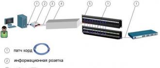
Distribution panel (patch panel): 24 ports, everything is the same with a switch. It is to the patch panel that all lines from workstations and servers will be connected.
Panel (block) of power sockets: according to the amount of connected equipment in the cabinet, plus a reserve of 1-2 sockets on the panel. Here we may well be faced with an “ambush” if we have to connect power supplies - there may not be enough (remember that 99.9% of the market is filled with surge protectors with sockets placed tightly and obliquely).
You can install a cheap, simple option (that’s when a shelf comes in handy, but you can also install it on the floor of a cabinet), or you can install a 19” UPS designed for installation in a cabinet.

So, having looked at the products offered on the market, we believe that we have decided on a cabinet: 14-high (14 U). For example, Molex MODBOX II 14U:
Possibility of using a 19-inch 1U fan in a cabinet
. Standard cabinet configuration:
. Lightweight steel profile provides the cabinet with greater rigidity and strength
. Aesthetic glass door with lock
. Door of universal design with the possibility of reversing (left, right)
. 19" frame with depth adjustment
. Grounding of all cabinet elements
. The cable entry holes are equipped with a protective brush to prevent dust from entering the cabinet
Switch. His choice is a more complex matter. I don’t want to consider very cheap switches. There are still more expensive (and very expensive) devices, but you still have to choose from two types: unmanaged and managed.
Let's take a look at the following two devices: ZyXEL Dimension ES-1024 and ES-2024:

It is a cost-effective Fast Ethernet solution and can be used to build highly efficient switched networks. The store-and-forward feature significantly reduces latency on high-speed networks. The switch is designed for workgroups, departments, or backbone computing environments for small and medium-sized enterprises. Due to its large address table and high performance, the switch is an excellent solution for connecting departmental networks to a corporate backbone or connecting network segments.
Specifications:
24-Port Fast Ethernet Switch
. Compliant with IEEE 802.3, 802.3u and 802.3x standards
. RJ-45 Ethernet ports with automatic 10/100 Mbps speed selection
. Automatic detection of crossover cable connections on all RJ-45 10/100 Mbps Ethernet ports
. Supports Back-Pressure-Base flow control on half-duplex ports
. Support Pause-Frame-Base flow control on full duplex ports
. Support for store-and-forward switching
. Supports automatic address detection
. Maximum forwarding speed over a wired network
. Built-in MAC address table (8K MAC address capacity)
. LED indicators for power, LK/ACT and FD/COL

Application of the ES-2024 switch will allow you to unite a group of users and connect them to the corporate network via high-speed lines. Additionally, it will be possible, thanks to the use of iStackingTM technology, to combine a group of switches for network management, regardless of their location.
Specifications:
24 RJ-45 ports with auto 10/100 Ethernet speed and auto crossover cable detection
. 2 10/100/1000 Ethernet ports
. 2 mini-GBIC slots combined with ports
. 8.8 Gbps non-blocking switch bus
. Supports IEEE 802.3u, 802.3ab, 802.3z, 802.3x, 802.1D, 802.1w, 802.1p protocols
. MAC address table 10Kb
. VLAN support: Port-based and 802.1Q
. Ability to limit port speed
. 64 static VLANs and up to 2Kb dynamic VLANs
. MAC address filtering
. Supports ZyXEL iStacking™, up to 8 switches (in the future up to 24) controlled by one IP address
. Control via RS-232 and WEB interface
. Telnet CLI
. SNMP V2c(RFC 1213, 1493, 1643, 1757, 2647)
. IP management: static IP or DHCP client
. Firmware update via FTP
. Updating and saving system configuration
. Standard 19" rack mount
As you can see, there is a difference, and a very serious one. There is a difference in price - approximately 100 and 450 dollars. But, if the first switch is a decent, but “dumb” box, then the second is in some sense intelligent, with much greater functionality and controllability, with potentially strong sides. We choose the second option. We want to build a good network, right?
By the way, right now is the time to ask the question, why are we actually building a “hundredth” network? Nowadays, every second computer has not just a gigabit network interface, but two gigabit ones?
This is the case where you can safely save. The fact is that a 100-megabit network is more than enough for office work. If, moreover, the switch is decent! Yes, and on the two gigabit interfaces of the selected switch, we can safely “plant”, for example, two servers. This is just for their benefit, the servers.
Of course, you can take something like the ZyXEL GS-2024 and put everyone on a gigabit channel, but this is just a case of unreasonable spending of money, and for that kind of money we can buy the entire cabinet with a more complete set.

Patch panel. This is also a case where you shouldn’t save much. We choose a panel like Molex 19" 24xRJ45, KATT, 568B, UTP, PowerCat 5e, 1U.
Category 5e compliant. The compensation system is implemented directly on the printed circuit board. The use of KATT type connectors speeds up and simplifies cable installation. Dedicated space for channel marking. The panel is powder coated. All necessary fastening and marking elements are supplied in the kit.
There are many options here, as already mentioned, you can install any cheap one, you can get it more expensive, you can have a 19” rack version - it will be absolutely beautiful. Who doesn't know APC? For example, you can look at this UPS:

APC Smart-UPS SC 1500VA 230V - 2U Rackmount/Tower
Or like this:

Without delving into the specifications, we note that many devices are equipped upon request with guides for installing a UPS in a 19" rack. It is also possible to equip, if desired, an SNMP module for monitoring and managing the UPS over a computer network. Of course, this will cost money, but may turn out to be very convenient. Let's choose IPPON. It should be noted that models 1500, 2000 and 3000 can be equipped with SNMP support, but 750 and 1000 cannot.
Power socket block:

Without any special comments - maybe you can find something cheaper and simpler. But a dozen “strangled raccoons” won’t make a difference.
The only thing left to remember is to decide whether a fan unit is needed in the cabinet? An expensive pleasure, especially when paired with a thermostat unit. However, let’s relate this to the specifics of the location/office.

We’ve more or less sorted out the closet, all that remains are all sorts of “little things”, without taking into account which there will be annoying delays later:
* Screws with nuts for mounting equipment in the cabinet;
* Nylon non-opening ties for laying and fastening cables (packs of 100 pieces, 100, 150, 200 mm long);
* Cable markings (adhesive sheets with a protective layer).
In fact, we got to the SCS itself. A very important “detail” is the cable that will be used to wire the SCS. Yes, again the call not to save. A good twisted pair cable is a good investment. We take Molex, unshielded UTP PowerCat 5e cable.

The cable is the core element of the PowerCat product line. The line is designed for use in high-speed telecommunications networks (for example GigaEthernet 1000Base-T).
We will, of course, come to the subscriber sockets, but what next? Next - buy the required number of patch cords to connect workstations. Naturally, you need to think about the length, look at the mentioned office plan. But that is not all. You also need a strainded cable (regular - solid). This is a special twisted pair, “soft”, from which patch cords are made. After all, sooner or later you will definitely need a patch cord of a greater length than is available ready-made at hand (if there are any left at all by that time). In addition, you can (or necessary - as you wish) it will be to make short - 30-50 cm, patch cords for cross-connecting SCS lines and active equipment in the cabinet itself. Therefore, we “take a pencil” for a couple more packages of RJ45 connectors, in common parlance - “chips.” And packaging of rubber caps for them. It is better to take the caps soft and with a slot for the “chip” retainer, and not with a “pimple” for the retainer.
We have almost reached the network interfaces on user computers, but subscriber sockets are still needed. Is anyone against such a wonderful thing as Molex OFFICE BLOCK 2xRJ45? ;-)

Category 5e compliant. The modules are designed for high-speed telecommunication networks. Possibility of cable entry from the sides, top or rear. As standard, the modules are equipped with dust curtains. Convenient channel marking. The built-in magnet simplifies the installation of modules on metal surfaces. Possibility of fastening with screws. Cable fastening inside the module without cable clamps. Free choice of connection sequence (568A/B). "KATT" type connector for easy installation. The kit includes mounting elements. .
Here you need to decide on the quantity. After all, there are single options. Let's take the office plan again. There is another important point in determining the installation locations for sockets - it is advisable to add one or two additional SCS lines to each office. One - just “just in case”. What if the layout in the office changes a little or someone needs to connect a laptop? The second is a good idea to have for a print server, for organizing network printing. It’s very nice to have one or two network printers per office or office that work without the problems and whims of the owner (or Windows).
Do you think that's it? No. Another factor that is present in any office has been forgotten - telephony. It’s very good to think about this: if telephones must be connected to some workplaces, then why not make the wiring in a common SCS? After all, the issue can be solved simply: throw a line or two to the necessary places, install an RJ-12 socket next to the RJ-45, it can even be in one case (block). In a socket - DECT, for example, with several handsets, and in a cabinet we draw a line (lines) from the PBX - they can be placed on sockets carefully glued with Velcro inside and on the sides. Lines from workplaces are on them.
It seems like it’s time to take on the cable duct and dowel-nails? Yes. It is time. But this is already clear to any handy man; let’s not dwell on this for long. You just need to take into account the number of lines being laid in the cable channel. And, of course, a small supply is needed. It is very good if the office has a suspended ceiling; the lines can be stretched behind it directly to the workplace and lowered in a cable channel along the wall. When drawing lines, it’s a good idea to label them (as well as sockets in the future). The simplest method is the first socket to the left of the door - No. 1, then in a circle.
Having stretched the lines, you can start splitting the patch panel and sockets. Needless to say, this work requires precision and skill. It is at this moment that marking the lines will be useful to us - if all the lines are split in order, then in the further operation of the SCS it will be possible to practically do without an installation map (layout), something like this:
Socket
However, this card is still necessary in the future. It will definitely come in handy.
When laying cables, you need to follow a few simple rules (just simple, we won’t go deep into standards and other ISOs):
* Do not bend, rub or step on the cable. Cable bending is allowed: during installation - 8, and during operation - 4 radii of the cable itself;
* Do not lay lines next to power lines: if there is a need to lay them in parallel - at a distance of at least 20 cm;
* It is allowed to cross power lines at right angles;
* Testing with a cable tester is required.
Separately about the last point. Remember the joke about the Japanese supply of something there? “Dear customers! We don’t know why you need this, but we still decided to put one defective chip in the boxes for every ten thousand, according to your requirements.” Yes, you can just split it and forget it. An experienced installer makes no mistakes. However, a truly experienced installer will definitely check not only the line layout, but also the quality.
Now we have reached the most interesting moment. If we check small things with a simple and cheap tester, then testing and certifying the lines - no, it won’t work:

Which exit? I really don’t want to leave the issue of line quality unresolved. There are three options. The first is to buy a good tester, for example:
But, alas, we really feel sorry for the $6,000, even for such a wonderful and necessary device.

It is a compact, portable tool used to qualify, test and troubleshoot coaxial and twisted pair cables in local area networks. The tester is recommended by leading manufacturers of information cable systems for testing for certification of systems up to Class E inclusive. The high level of reliability, convenience and accuracy of the device ensured it one of the first places among products of this class. For fast and high-quality testing of cable connections in an extended frequency range up to 350 MHz, digital pulse signal processing technologies are used.
The second option is to invite a friend of the admin or installer who has this or a similar device. Of course, first buy a case of good beer. Half an hour of work, plus a beer evening in the pleasant company of a friend.
The third option is to officially invite specialists from any company that provides such services. And pay for these services. This is not so much, especially if you do not require a certificate on paper.
Remote workstations
Having “finished” (quotes because we must first plan everything and make the necessary purchases and negotiations) with the work at the main office, we remember the warehouse and store.
Now (in these notes) we will consider not a “sophisticated” solution like VPN, but the simplest one - organizing the connection of computer networks with subnets (workstations with a network) via a dedicated line. Effective, cheap and cheerful. By the way, dedicated telephones, of course, should be placed in a closet and connected to sockets, just like telephones.

If the distance and, accordingly, the resistance of the dedicated line is small, you can try installing a pair of “bridges”, for example, from the already mentioned company ZyXEL Prestige 841C and ZyXEL Prestige 841. Model “C” is a “master”, so this device is best installed at the head office. These are inexpensive devices that work using VDSL technology, but they provide the necessary results for our task. What ZyXEL says:
Depending on the type and condition of the cable, as well as the distance, the Prestige 841 paired with the Prestige 841C provides the following data exchange speed:
Toward the subscriber - ranging from 4.17 to 18.75 Mbit/s
. in the direction from the subscriber - from 1.56 to 16.67 Mbit/s
. the total line capacity can reach 35 Mbit/s
Specifications:
VDSL Ethernet bridge
. Connection of local networks at a speed of 15 Mbit/s up to 1.5 km
. Plug&Play, transparent for all protocols
. Work in pairs
. Desktop version
. Non-volatile memory (Flash ROM)
. Size: 181 x 128 x 30 mm
This option will give 18 Mb in each direction, ideally, of course. This is VDSL.
There is one more benefit to using the Prestige 841. These devices have a built-in splitter, and we can get “free” telephony from a remote location. It is enough to plug the remote workplace telephone into the “phone” connector on one side, and connect an office mini-PBX on the other side.
If the VDSL bridges do not “stretch” the line, you need to look at other devices, xDSL. For example - something from the 79x series ZyXEL, SHDSL.

Optimization of the hardware and the use of advanced technologies made it possible not only to reduce the dimensions of the device, but also to reduce the cost and improve the functional characteristics. provide a symmetrical connection at speeds up to 2.3 Mbit/s and can operate on a dedicated 2-wire line both in point-to-point mode and as a client of an Internet provider hub.
Specifications:
. SHDSL router
. Supports G.991.2 at speeds up to 2.3 Mbps symmetrically
. Connecting networks or accessing the Internet over long distances
. Encapsulation PPPoA, PPPoE, RFC-1483
. TCP/IP routing, Full NAT, packet filtering
. Support IP Policy Routing, UPnP, connection redundancy
. Management via console, Telnet, Web, SNMP
The ideal speed is 2.3Mb over two wires. If you “charge” 4 wires, the speed will be correspondingly higher. However, these devices will cost a large amount - $400-500 per pair. In any case, roughly speaking, the worse the quality of the line, the lower the speed and the higher the costs. However, we will postpone setting up (tuning) devices for the future; this is a separate conversation, especially since in the case of VDSL 841 this does not make too much sense at all. xDSL devices should be placed on a shelf in the closet. I told you it wouldn't be empty.
Internet connection

ZyXEL Prestige-660
A modern office is unthinkable without the Internet. To connect we can use ADSL technology, for example - ZyXEL Prestige 660.
As ZyXEL describes this device:
Modem P-660R belongs to the fourth generation of ADSL modems and combines in one device the functionality necessary to connect an existing office or home network to the Internet: ADSL2+ modem, router and firewall. The modem will provide your office with a constant Internet connection that is fast and secure. Installation and maintenance of the P-660R modem is simple and will not cause any problems even for untrained users.
Main advantages of ZyXEL Prestige 660:
* High-speed Internet - up to 24 Mbit/s
* Reliable connection on problem lines
* Free phone
* Permanent connection
* Does not require driver installation
* Works with W
Federal Agency for Education
State educational institution
Ufa State Aviation Technical University
In addition to the main components, the network may include uninterruptible power supplies, backup devices, modern dynamically distributed objects and various types of servers (such as file servers, print servers or archive servers).
When creating a LAN, the developer faces a problem: with known data on the purpose, list of LAN functions and the basic requirements for a set of hardware and software LAN tools, build a network, that is, solve the following problems:
Determine the LAN architecture: select the types of LAN components;
Assess LAN performance indicators;
Determine the cost of the LAN.
In this case, the rules for connecting LAN components based on network standardization and their limitations specified by the manufacturers of LAN components must be taken into account.
The LAN configuration for an automated control system significantly depends on the characteristics of a specific application area. These features come down to the types of transmitted information (data, speech, graphics), spatial location of subscriber systems, intensities of information flows, permissible delays of information during transmission between sources and recipients, volumes of data processing in sources and consumers, characteristics of subscriber stations, external climatic, electromagnetic factors, ergonomic requirements, reliability requirements, LAN cost, etc.
The initial data for designing a LAN can be obtained during a pre-design analysis of the application area for which the automated control system is to be created. This data is then refined as a result of decision-making at the stages of LAN design and the construction of increasingly accurate models of the automated control system, which allows the requirements for it to be formulated in the “Technical Specifications for the LAN”. The best LAN is the one that satisfies all user requirements formulated in the terms of reference for the development of a LAN, with a minimum amount of capital and operating costs.
GOAL OF THE WORK
Gaining skills in choosing a topology, elements of a local computer network, as well as calculating signal delay time.
BRIEF THEORETICAL INFORMATION
Designing a LAN configuration refers to the stage of designing technical support for automated systems and is carried out at this stage after distributing the functions of the automated system among LAN subscriber stations, selecting the types of subscriber stations, and determining the physical location of subscriber stations.
The design brief includes LAN requirements, indications of available hardware and software components, knowledge of LAN synthesis and analysis methods, preferences and criteria for comparing LAN configuration options. Let's consider topology options and the composition of local area network components.
1. LAN topology.
The topology of a network is determined by the way its nodes are connected by communication channels. In practice, 4 basic topologies are used:
Star-shaped (Fig. 1);
Ring (Fig. 2);
Tire (Fig. 3);
Tree-like (Fig. 1*);
Cellular (Fig. 4).
Computer network topologies can be very different, but for local area networks only three are typical: ring, bus, star. Sometimes, to simplify things, the terms ring, tire and star are used.
Tree topology (hierarchical, vertical). In this topology, nodes perform other, more intelligent functions than in a star topology. Network hierarchical topology is currently one of the most common. The network management software is relatively simple, and this topology provides a focal point for management and error diagnosis. In most cases, the network is controlled by station A at the highest level of the hierarchy, and traffic propagation between stations is also initiated by station A. Many firms implement a distributed approach to a hierarchical network, in which, in a system of slave stations, each station provides direct control of stations lower in the hierarchy. Station A controls stations B and C. This reduces the load on the LAN through the allocation of segments.
Mesh topology (mixed or multi-connected). A network with a mesh topology is, as a rule, an incompletely connected network of message switching nodes (channels, packets) to which end systems are connected. All CS are dedicated point-to-point. This type of topology is most often used in large-scale and regional computer networks, but they are sometimes used in LANs. The attractiveness of the mesh topology lies in its relative resistance to overloads and failures. Due to the multiple paths from station to station, traffic can be directed to bypass failed or busy nodes.
Network topology affects reliability, flexibility, throughput, network cost, and response time (see Appendix 1).
The selected network topology must correspond to the geographic location of the LAN network, the requirements established for the network characteristics listed in the table. Topology affects the length of communication lines.

Fig.1. Star topology Fig. 2 Ring topology
https://pandia.ru/text/78/549/images/image004_82.gif" width="279" height="292 src=">
Rice. 1* Distributed star topology
Fig.3 Topology
linear bus
transparent" connection of several local networks or several segments of the same network with different protocols. Internal bridges connect most LANs using network cards in a file server. With an external bridge, a workstation is used as a service computer with two network adapters from two different ones, however, homogeneous computer networks.
In the case when the connected networks differ at all levels of control, an end system of the type Gateway, in which coordination is carried out at the level of application processes. By using gateway systems using different operating environments and high-level protocols are interconnected
9. Initial data for the task
Users: students, teachers, engineers, programmers, laboratory assistants, technicians of the Department of Automated Control Systems of UGATU.
Functions:
1) implementation of the educational process in laboratory and practical classes, completion of coursework and diploma projects;
2) organization of the educational process, preparation for conducting classes, development of methodological support;
3) development of software for working on the network;
4) prevention and repair of equipment.
Calculation of the cost of LAN equipment:
The LAN must allow the connection of a large set of standard and special devices, including: computers, terminals, external memory devices, printers, plotters, fax devices, monitoring and control equipment, equipment for connecting to other LANs and networks (including telephone ones) etc.
The LAN must deliver data to the recipient with a high degree of reliability (the network availability factor must be at least 0.96), must comply with existing standards, provide a “transparent” data transfer mode, allow easy connection of new devices and disconnection of old ones without disrupting the network for no more than 1 second ; the reliability of data transmission should be no more than +1E-8.
11. List of tasks for LAN design
11.1. Select a LAN topology (and justify the choice).
11.2. Draw a functional diagram of a LAN and make a list of hardware.
11.3. Select the optimal LAN configuration.
11.4. Make an approximate routing of the cable network and calculate the length of the cable connection for the selected topology, taking into account transitions between floors. Since there are restrictions on the maximum length of one LAN segment for a given cable type and a given number of workstations, the need to use repeaters must be determined.
11.5. Determine the packet propagation delay in the designed LAN.
For calculations, it is necessary to select a path in the network with the maximum double travel time and the maximum number of repeaters (hubs) between computers, that is, the path of maximum length. If there are several such paths, then the calculation must be made for each of them.
The calculation in this case is carried out on the basis of Table 2.
To calculate the total round trip time for a network segment, multiply the segment length by the delay per meter taken from the second column of the table. If a segment has a maximum length, then you can immediately take the maximum delay value for this segment from the third column of the table.
Then the delays of the segments included in the path of maximum length must be summed up and added to this sum the delay value for the transceiver nodes of two subscribers (these are the top three lines of the table) and the delay values for all repeaters (hubs) included in this path (these are the bottom three lines tables).
The total delay must be less than 512 bit intervals. It must be remembered that the standard IEEE 802.3u recommends leaving a margin of 1 – 4 bit intervals to account for cables inside junction boxes and measurement errors. It is better to compare the total delay to 508 bit intervals rather than 512 bit intervals.
Table 2.
Double delays of network components Fast Ethernet(delay values are given in bit intervals)
Segment type | Delay per meter | Max. delay |
Two subscribers TX/FX | Two subscribers TX/FX |
|
Two subscribers T4 | Two subscribers T4 |
|
One subscriber T4 and one TX/FX | One subscriber T4 and one TX/FX |
|
Shielded twisted pair | ||
Fiber optic cable | ||
Class I repeater (hub) |
||
TX/FX | Class II repeater (hub) with ports TX/FX |
|
Class II repeater (hub) with ports T4 | Class II repeater (hub) with ports T4 |
All delays given in the table are for the worst case. If the timing characteristics of specific cables, hubs and adapters are known, then it is almost always preferable to use them. In some cases, this can provide a noticeable increase in the permissible network size.
Example calculation for the network shown in Fig. 5:
There are two maximum paths here: between computers (segments A, B and C) and between the upper (as shown in the figure) computer and the switch (segments A, B and D). Both of these paths include two 100-meter segments and one 5-meter segment. Let us assume that all segments are 100BASE-TX and are performed on category 5 cable. For two 100-meter segments (maximum length), the delay value of 111.2 bit intervals should be taken from the table.

Rice 5. Example of maximum network configuration Fast Ethernet
For a 5 meter segment, when calculating the delay, multiply 1.112 (delay per meter) by the cable length (5 meters): 1.112 * 5 = 5.56 bit intervals.
Delay value for two subscribers TX from the table – 100 bit intervals.
From the table of delay values for two class II repeaters - 92 bit intervals each.
All listed delays are summed up:
111,2 + 111,2 + 5,56 + 100 + 92 + 92 = 511,96
this is less than 512, therefore, this network will be operational, although at the limit, which is not recommended.
11.6. Determine LAN reliability
For a model with two states (working and not working), the probability of the component working, or, more simply, reliability, can be understood in different ways. The most common formulations are:
1. component availability
2. component reliability
Availability is used in the context of repairable systems. From the above it follows that a component can be in one of three states: working, not working, or in the process of being restored. The availability of a component is defined as the probability of its operation at a random point in time. The availability value is assessed taking into account the average time to restore to a working state and the average time to be in a non-working state. Reliability can be written:
______________average time to failure______________
mean time to failure + mean recovery time
Quantitative values of AIS reliability indicators must be no worse than the following:
The average time between failures of the AIS software and hardware complex (CPTS) must be at least 500 hours;
The mean time between failures of a single AIS communication channel must be at least 300 hours;
The mean time between failures of AIS servers must be at least 10,000 hours;
The mean time between failures of the PC (as part of the automated workplace) must be at least 5000 hours;
The mean time between failures of a single function of the application software (SPO) of the AIS CPTS must be at least 1500 hours;
The average time to restore the functionality of the AIS CPTS should be no more than 30 minutes; wherein:
The average time to restore the functionality of a control system after failures of technical equipment should be no more than 20 minutes, excluding organizational downtime;
The average time to restore the functionality of a control system after a failure of general or special AIS software is no more than 20 minutes, excluding organizational downtime;
The average time to restore the functionality of a single communication channel of a CPTS should be no more than 3 hours;
The average time to restore the functionality of the CPTS in the event of a failure or malfunction due to algorithmic errors in the application software of the software and technology complex (STC) of the AIS, without eliminating which the further functioning of the CPTS or STC of the AIS is impossible - up to 8 hours (taking into account the time to eliminate errors).
12.1. List of stages of designing a LAN configuration, indicating the design decisions taken.
12.2. Functional diagram of a LAN (drawing of a LAN indicating brands of equipment and communication lines). In the diagram, it is recommended to note the number of workstations in different LAN segments, possible expansion reserves and bottlenecks.
12.3. Results of calculations of the cost of LAN (compiled in a table indicating the name, number of units, price and cost). When calculating the cost, take into account the costs of designing and installing a LAN.
Name | Quantity | Price | Note |
||
12.4 Calculate the LAN delay and its reliability.
Annex 1.
Table 1
Comparative data on LAN characteristics
Characteristic | Qualitative performance assessment |
||
Bus and tree network | Ring network | Star network |
|
Response time trep. | In the marker bus | trep. There is a function of the number of network nodes | totv. depends on the load and timing characteristics of the central node |
Bandwidth WITH | In a token bus it depends on the number of nodes. In a random bus WITH increases during sporadic light loads and decreases when exchanging long messages in stationary mode | WITH crashes when adding new nodes | WITH depends on the performance of the central node and the capacity of subscriber channels |
Reliability | System failures do not affect the performance of the rest of the network. A broken cable disables the bus LAN. | The failure of one speaker does not lead to the failure of the entire network. However, the use of bypass schemes allows you to protect the network from AC failures | System failures do not affect the performance of the rest of the network. The reliability of the LAN is determined by the reliability of the central node |
To a set of parameters for LAN communication lines include: bandwidth and data rate, point-to-point, multipoint and/or broadcast capability (i.e. permissible applications), maximum extension and number of connected subscriber systems, topological flexibility and installation complexity, interference immunity and cost.
The main problem is to simultaneously ensure the indicators, for example, the highest data transfer rate is limited by the maximum possible data transfer distance, which still ensures the required level of data protection. Easy scalability and ease of expansion of the cable system affect its cost.
Physical location conditions help determine the best cable type and topology. Each cable type has its own maximum length restrictions: twisted pair ensures work over short periods, single channel coaxial cable - over long distances, multichannel coaxial and fiber optic cable - over very long distances.
The data transfer speed is also limited by the capabilities of the cable: the highest is fiber optic, then they go single-channel coaxial, multi-channel cables And twisted pair Available cables can be selected to match the required characteristics.
Fast Ethernet 802.3u is not an independent standard, but is an addition to the existing 802.3 standard in the form of chapters. The new Fast Ethernet technology has retained all MAC classical level Ethernet, but the throughput has been increased to 100 Mbps. Consequently, since the throughput has increased by 10 times, the bit interval has decreased by 10 times, and is now equal to 0.01 μs. Therefore in technology Fast Ethernet the frame transmission time of the minimum length in bit intervals remained the same, but equal to 5.75 μs. Limit on total network length Fast Ethernet decreased to 200 meters. All the differences in technology Fast Ethernet from Ethernet focused on the physical level. Levels MAC And LLC V Fast Ethernet remained absolutely the same.
The official 802.3u standard established three different specifications for the physical layer Fast Ethernet:
- 100Base-TX- for two-pair cable on unshielded twisted pair UTP category 5 or shielded twisted pair STP Type 1;
- 100Base-T4- for four-pair cable on unshielded twisted pair UTP categories 3, 4 or 5;
100Base-FX - for multimode fiber optic cable, two fibers are used.
IN Ethernet 2 classes of concentrators are introduced: 1st class and 2nd class. Class 1 hubs support all physical layer encoding types ( TX, FX, T4), i.e. the ports may be different. Class 2 hubs support only one type of physical layer encoding: either TX/FX, or T4.
Maximum distances from hub to node:
- TX– 100 m, FX– multimode: 412 m (half duplex), 2 km (full). Single-mode: 412 m (half duplex), up to 100 km (full duplex), T4– 100 m.
There can only be one 1st class hub in the network, two 2nd class hubs, but the distance between them is 5 m.
Twisted pair (UTP)
The cheapest cable connection is a two-wire twisted wire connection, often called twisted pair (twisted pair). It allows you to transmit information at speeds of up to 10-100 Mbit/s, is easily expandable, but is noise-immune. The cable length cannot exceed 1000 m at a transmission speed of 1 Mbit/s. The advantages are low price and easy installation. To increase the noise immunity of information, shielded twisted pair cables are often used. This increases the cost of twisted pair and brings its price closer to the price of coaxial cable.
1. A traditional telephone cable, it can carry voice but not data.
2. Capable of transmitting data at speeds up to 4 Mbit/s. 4 twisted pairs.
3. A cable capable of transmitting data at speeds up to 10 Mbit/s. 4 twisted pairs with nine turns per meter.
4. A cable capable of transmitting data at speeds up to 16 Mbit/s. 4 twisted pairs.
5. A cable capable of transmitting data at speeds up to 100 Mbit/s. Consists of four twisted pairs of copper wire.
6. The cable, capable of transmitting data at speeds up to 1 Gb/s, consists of 4 twisted pairs.
Coaxial cable It has an average price, is noise-resistant and is used for communication over long distances (several kilometers). Information transfer speeds range from 1 to 10 Mbit/s, and in some cases can reach 50 Mbit/s. Coaxial cable used for basic and broadband information transmission.
Broadband coaxial cable immune to interference, easy to expand, but its price is high. The information transfer rate is 500 Mbit/s. When transmitting information in the base frequency band over a distance of more than 1.5 km, an amplifier or so-called repeater is required ( repeater). Therefore, the total distance when transmitting information increases to 10 km. For computer networks with a bus or tree topology, the coaxial cable must have a terminator at the end.
Ethernet-cable is also a coaxial cable with a characteristic impedance of 50 ohms. It is also called thick Ethernet (thick) or yellow cable (yellow cable). It uses a 15-pin standard connection. Due to its noise immunity, it is an expensive alternative to conventional coaxial cables. The maximum available distance without a repeater does not exceed 500 m, and the total network distance Ethernet - about 3000 m. Ethernet- the cable, due to its main topology, uses only one load resistor at the end.
Cheaper than Ethernet-cable is the connection Cheapernet-cable or, as it is often called, thin (thin) Ethernet. It is also a 50 ohm coaxial cable with a transfer rate of 10 million bps.
When connecting segments Cheapernet-cable repeaters are also required. Computer networks with Cheapernet-cable have a low cost and minimal costs when building up. Network cards are connected using widely used small-sized bayonet connectors ( SR-50). No additional shielding is required. The cable is connected to the PC using tee connectors ( Tconnectors). The distance between two workstations without repeaters can be a maximum of 300 m, and the total distance for the network is up to Cheapemet-cable - about 1000 m. Transceiver Cheapernet located on the network board and is used both for galvanic isolation between adapters and for amplifying an external signal.
The most expensive are optical conductors, also called fiberglass cable. The speed of information dissemination through them reaches several gigabits per second. There is virtually no external interference. They are used where electromagnetic interference fields occur or information transmission over very long distances is required without the use of repeaters. They have anti-eavesdropping properties, since the branching technique in fiber optic cables is very complex. Fiber optic conductors are combined into a LAN using a star connection.
2 types of optical fiber:
1)single mode cable– a central conductor of small diameter is used, commensurate with the wavelength of light (5-10 µm). In this case, all light rays propagate along the optical axis of the light guide without being reflected from the external conductor. A laser is used. Cable length – 100 km or more.
2) multimode cable - use wider internal cores (40-100 µm). In the inner conductor, several light rays simultaneously exist, reflecting from the outer conductor at different angles. Reflection angle is called beam fashion. LEDs are used as a radiation source. Cable length – up to 2 km.
BIBLIOGRAPHY
Olifer network. Principles, technologies, protocols. - St. Petersburg: Peter, 20 p.
Guk, M. Local network hardware. Encyclopedia. - St. Petersburg. : Publishing house Peter, 2004 .- 576 p.
Novikov, networks: architecture, algorithms, design. - M.: EKOM, 2002. - 312 p. : ill. ; 23cm. - ISBN -8.
Epaneshnikov, computer networks / , .- Moscow: Dialogue-MEPhI, 2005 .- 224 p.
1. http://*****/, a system for automatically creating local area network projects
Compiled by: Nikolai Mikhailovich Dubinin
Ruslan Nikolaevich Agapov
Gennady Vladimirovich Startsev
DESIGNING A LOCAL COMPUTER NETWORK
Laboratory workshop on the discipline
"Computer networks and telecommunications"
Signed for publication on 05/05/2008. Format 60x84 1/16.
Offset paper. Printing is flat. Times New Roman typeface.
Conditional oven l. . Conditional cr. - Ott. . Uch. – ed. l. .
Circulation 100 copies. Order No.
GOU VPO Ufa State Aviation
Technical University
Center for Operational Printing of UGATU
Ufa center, st. K. Marx, 12
LAN is a network designed for processing data storage and transmission and is a cable system of a building object or a group of building objects. LANs are used to solve problems such as: Data distribution. In this regard, there is no need to have drives for storing the same information at each workplace; Resource distribution. Peripheral devices can be accessed by all LAN users.
Share your work on social networks
If this work does not suit you, at the bottom of the page there is a list of similar works. You can also use the search button
COURSE WORK
|
Completed by a student of group 1ISz-410 |
|
group |
|
areas of training (specialties) |
|
230400.62. Information systems and technologies |
|
code, name |
|
Belov Nikita Sergeevich |
|
Full Name |
|
Supervisor |
|
Selyanichev Oleg Leonidovich |
|
Full Name |
|
Associate Professor, Ph.D. |
|
Job title |
|
Submission date |
|
« » |
|
Conclusion on admission to defense |
|
Grade _______________, _______________ |
|
number of points |
|
Teacher's signature_________________ |
Cherepovets, 2015
Introduction
Currently, local computer networks are widely used in enterprises and institutions.
LAN is a network designed for processing, storing and transmitting data, and is a cable system of an object (building) or a group of objects (buildings).
The main purpose of these networks is to provide access to network-wide (information, software and hardware) resources. In addition, LANs allow enterprise employees to quickly exchange information with each other.
LANs are used to solve problems such as:
- Data distribution. Data on the local network is stored on a central PC and can be accessed on workstations. In this regard, there is no need to have drives for storing the same information at each workplace;
- Resource distribution. Peripheral devices can be accessed by all LAN users. Such devices can be, for example, a scanner or laser printer;
- Distribution of programs. All LAN users can share access to programs that have been centrally installed on one of the computers.
The basis for designing a LAN is the taskfor course work in the discipline"Information and computer networks." Namely, select equipment, data transfer protocols and indicate recommendations for setting up software for organizing the BelovTansAvto IP.
Problems solved by the organization
IP "BelovTansAvto" transport company engaged in cargo transportation in the city of Vologda and beyond.
As part of this course work, it is necessary to design a local network for the BelovTansAvto IP. Each employee’s workplace is equipped with a personal computer, which in turn must be connected into a local network to exchange data with each other. In addition, the office is equipped with printing devices, which must be accessed from each PC through this network.
- Organizational premises planning
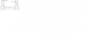
The office space consists of three workstations, as well as a utility room. In total there are 3 computers and 1 printing device. The floor plan is shown below.
Floor plan
- Selection of equipment parameters
To choose the right office computer from the variety of options offered, first of all, let’s limit the range of tasks that will have to be solved with its help.
Without a doubt, the first place here is the software package of the same name from Microsoft , working, naturally, under the operating system of the same company. In most cases, this includes email programs and browsers.
Further, everything depends on the specialization of the company and the imagination of those responsible for choosing the software. In general, the matter is limited to not the newest, but proven and stable versions of packages for working with text, graphics, electronic drawings and diagrams, databases, audio, video materials, etc.
This organization works with a software package from Microsoft.
Let's create a configuration PC for staff:
|
Motherboard |
ASUS M5A78L-M / USB3 (RTL) SocketAM3+< AMD 760G >PCI-E+SVGA+DVI+HDMI GbLAN SATA RAID MicroATX 4DDR-III |
2550 |
|
CPU |
AMD FX-4300 (FD4300W) 3.8 GHz / 4core / 4+4Mb / 95W / 5200 MHz Socket AM3+ |
3400 |
|
CPU cooler |
DEEPCOOL GAMMAXX 200, 92mm |
|
|
HDD |
1 Tb SATA 6Gb/s Seagate Barracuda< ST1000DM003 >3.5" 7200rpm 64Mb |
2690 |
|
RAM |
Kingston ValueRAM< KVR1333D3N9 / 4G>DDR-III DIMM 4Gb< PC3-10600>CL9 |
1950 |
|
Frame |
Cooler Master< RC-350-KKN1-GP >CMP350 Black&Black ATX Without PSU |
1920 |
|
power unit |
FSP/SPI |
1420 |
|
D VD drive |
DVD RAM & DVD±R/RW & CDRW LG GH22LS50 |
When choosing a server computer, you must consider the following characteristics:
- processor performance;
- amount of RAM;
- speed and hard drive capacity.
You must also select software for the server and workstations. Licensed copies of the OS are already installed on workstations Microsoft Windows 7 and Windows 8, and we will select the operating system for the server based on compatibility with these systems.
All invoices, reports, reports and much more are done using the printer. When purchasing a multifunction printer, printer, scanner, etc., you should buy it with a built-in “print server,” that is, a built-in network card. This will save you from purchasing an external print server and the cost of additional setup.
An example of a printing device. Kyocera FS-6525MFP
Characteristics:
Device printer/scanner/copier/fax
Print type black and white
Laser printing technology
Desktop placement
Interfaces Ethernet (RJ-45), USB 2.0
Price: 42,860
- network hardware
Network equipment devices necessary for the operation of a computer network, for example: router, switch, hub. Let us describe the equipment that will be used in this organization.
Despite the intensive development of wireless technologies, cable data transmission lines still remain the most reliable, noise-resistant, and relatively inexpensive solution for organizing scalable computer networks with access control. The choice of twisted pair when designing and installing such networks is one of the main tasks.
The twisted pair parameters that must be taken into account during design are as follows:
- Category . According to telecommunications cabling standards EIA/TIA 568 and ISO 11801, there are ten of them: categories 1-4 do not meet modern requirements and are not currently used, and categories 7 and 7a are inferior in practicality to optical cable. Therefore, we will talk about categories 5, 5e, 6, 6a.
- Core material . Copper, or copper-plated aluminum. Plus, you should pay attention to copper plating technology: CCA, CCAA, CCAG, or CCAH
- Outer shell type:for external or internal installation
- Shielding type:for installation near strong sources of electromagnetic radiation
- Availability of cable or armorfor air laying, or laying in a room infested with rodents
An unprotected twisted pair cable is used to connect computers.(UTP Unshielded twisted pair) category 5e. Category 5e cable is the most common and is used to build computer networks.
Cost: 50 (meters) * 15 (rub. per meter) = 750 rub.

A switch will be used to connect computers into a single local network. Its main advantage is that during operation it forms a switching table by typing a list of MAC addresses, and according to it, data is sent. Each switch, after a short time of operation, “knows” which port each computer on the network is on.

NETGEAR FS116GE Switch
Switch characteristics.
Switch TP-LINK TL-SG1016D 16-Port Gigabit Switch
Number of portsswitch 16 x Ethernet 10/100 Mbit/s
Internal bandwidth 32 Gbps
Number of slots for additional interfaces no data
Management no data
Auto MDI/MDIX standard support
Dynamic routing protocols no data
Dimensions 286 x 27 x 103 mm
Price: 3,070 rub.
Lenovo ThinkServer TS140 70A4S00400 was selected as the server.
Lenovo ThinkServer TS140 This is a ready-made server from IBM, which has high quality, excellent performance and good scalability. Target audience growing companies that need the ability to further upgrade the server. The System x3100 series supports high-performance Intel E3 series processors. The server is optimized for quick deployment and subsequent monitoring of operation. The performance of this model (2582-K9G) is provided by the Intel E3-1225 v3 processor with optimization for multi-threaded applications. Pre-installed amount of RAM 4GB (high-performance DDR3 ECC is used). The server has a Micro ATX Tower (4U) form factor and is designed for floor installation. As the need for performance increases, the configuration can be changed.

Lenovo ThinkServer TS140
Server characteristics.
Characteristics:
Basic
Manufacturer Lenovo
Case form factor Micro ATX Tower
CPU
Processor manufacturer Intel
Xeon line
Clock frequency 3000 MHz
Number of cores 4
Processor model E3-1225V3
Number of installed processors 1
Maximum number of processors 1
RAM
Installed memory capacity 4096 MB
Memory type DDR-3
Number of slots 4
HDD
SATA interface
Number of installed disks 2
Volume of installed HDD 500 GB
Form factor HDD 3.5"
Maximum number of HDDs 4
Drive unit
Optical drive Yes
Net
Network interface Gigabit Ethernet (10/100/1000 Mbit/s)
Power supply 280 W
Price: 48,190 rub.
Also, to be able to access the Internet, it will be usedWi-Fi router. TP-LINK TL-WR841HP very fast router. The manufacturer claims a maximum data transfer rate of 750 Mbit/s. One of the important advantages of this model over many others is the ability to simultaneously use two frequency bands: 2.4 and 5 GHz. Thanks to this, users can simultaneously connect to the Internet from phones, smartphones, and from a laptop, PC or tablet. Another advantage of this model is that it comes with fairly powerful antennas that allow you to distribute the Internet via Wi-Fi over a distance of more than 200 m.

Wi-Fi routerTP-LINK 4*LAN WAN10/100M Atheros
Router characteristics.
Type: Wi-Fi hotspot
Interface: 4 x Fast Ethernet 10/100 Mbit/s
1 x WAN
VPN support: yes
Network characteristics Secure VPN protocols: PPTP,
PPPoE, L2TP, IPSec
Obtaining an IP address: Static IP, Dynamic IP
QoS: Supported
WMM (Wi-Fi Multimedia) support:
Supported
Virtual Server: Supported
WPS (Wi-Fi Protected Setup):
Supported
DMZ: Supported
NAT: Supported, Port Triggering
DHCP Server: Supported
output power
Wireless network 20 dBm
Wireless frequency 2.4/5 GHz
Management: web interface
Dimensions 225x33x140 mm
Features Firewall: SPI (Stateful Packet Inspection), Protection against DOS attacks, Time-based access control, Parental control, IP filtering, MAC address filtering, Domain filtering
Data transmission security schemes: WPA2-PSK; WPA-PSK; WPA2; WPA; WEP encryption with 64- or 128-bit key
Price: 4,350 rub.
- Logical, structural diagram of the network
The structure (topology) of a computer network usually refers to the physical arrangement of computers on the network relative to one another and the way they are connected by communication lines.
There are three main network topologies:
1. Network topology bus(bus), in which all computers are connected in parallel to one communication line and information from each computer is simultaneously transmitted to all other computers;
2. Star network topology(star), in which other peripheral computers are connected to one central computer, each of them using its own separate communication line;
3. Network topology ring(ring), in which each computer always transmits information to only one computer next in the chain, and receives information only from the previous computer in the chain, and this chain is closed in a “ring”.
Network topology "bus"
Star network topology
Ring network topology
In practice, combinations of the basic topology are often used, but most networks are focused on these three.
When designing a network for this organization, we will use the “Star” topology. Star topologyis the fastest of all computer network topologies, since data transfer between workstations passes through a central node (if its performance is good) over separate lines used only by these workstations. The frequency of requests to transfer information from one station to another is low compared to that achieved in other topologies. Network throughput is determined by the computing power of the node and is guaranteed for each workstation. There are no data collisions.
Cabling is quite simple as each workstation is connected to a node.
The central control node file server implements the optimal protection mechanism against unauthorized access to information. The entire computer network can be controlled from the center of the control node.

Network block diagram

Logical network diagram
The network must use some method of determining which node should use the communication lines and for how long. These functions are implemented by the network protocol, which is necessary to prevent more than one user from accessing the bus at any given time.
If two sets of data are placed on the network at the same time, data conflict and data loss occurs. There are currently two virtually standard network protocols in use: Ethernet and Token Ring.
This project will use the Gigabit Ethernet standard, which supports transmission speeds of up to 1000 Mbit/s. The selected subtype is 1000BASE-T, IEEE 802.3ab standard, using twisted pair cable of categories 5e or 6. All 4 pairs are involved in data transmission. Data transfer speed 250 Mbit/s over one pair.
Ethernet packet technology of computer networks, mainly local ones. Ethernet standards define wiring and electrical signals at the physical layer, frame formats, and media access control protocols at the data link layer of the OSI model. Ethernet is primarily described by IEEE group 802.3 standards.
Advantages of Ethernet:
- known technology;
- availability.
- Provides the fast, efficient data delivery needed for real-time data exchange.
- Network address structure
Each computer must have its own, unique name. But the workgroup name, on the contrary, must be the same on all computers. The group and computer name can be anything, but the most common names for groups are WORKGROUP or MSHOME . In addition to the name, the computer can also be provided with a description that will help you understand which computer you are talking about.
IP assignment -addresses and subnet masks:
Like the Internet, each computer on our local network must have its own IP -address consisting of numbers separated by dots. And this is not surprising, since in both cases communication is carried out using the protocol TCP/IP. IP -addresses of computers on the local network are most often assigned based on the following pattern: 192.168.0.X
The first part of the address remains unchanged in any case, and instead of X you can substitute any number in the range from 0 to 255. Since this organization has 3 computers, we will replace X with the computer number.
Example IP - computer addresses: 192.168.0.1.
IP -the address for the server will be 192.168.0.0, and for the printer 192.168.0.99.
Second setting option TCP/IP is called a "subnet mask". It should be the same on all computers: 255.255.255.0
- Network software
Windows 8 is used as the operating system. It includes all the functions that the Windows 7 version can boast of and also has a number of serious additions:
The functions of this OS include such as joining a domain, Group Policy (GP) control, searching for available printers, and automatic network backup.
Windows Server 2012 R2 will be installed on the server computer.
Windows Server 2012 R2 brings Microsoft's expertise in building and delivering global cloud services to the infrastructure with new capabilities and improvements for virtualization, management, storage, networking, virtual desktop infrastructure, access and information security, web and platform applications, as well as many other components.
If your organization's network uses 802.1X password authentication methods for wired and wireless connections through Ethernet switches and wireless access points, users of non-domain-joined computers and devices running Windows 8.1 and Windows Server 2012 R2 can bring Bring your devices into your organization and take advantage of password-based credential reuse.
When EAP and PEAP authentication methods are configured, users can provide their credentials the first time they connect to an organization's network, and then connect to all the resources they need without having to enter them again because the credentials are saved locally for repeated use. .
This is especially useful for users who connect to multiple network resources, such as intranet websites, enterprise printers, and a family of business applications.
For security reasons, when you disconnect your computer or device from the network, saved credentials are deleted.
This feature is available for non-domain-joined computers and devices running Windows 8.1 and Windows Server 2012 R2 if the following authentication methods are implemented on the network.
- Via EAP in combination with MSCHAP version 2 (PEAP-MS-CHAP v2)
- PEAP-EAP-MS-CHAP v2
- Via EAP-TTLS in combination with EAP-MS-CHAP v2
In Windows 8.1 and Windows Server 2012 R2, this feature is enabled by default.

Microsoft Windows Server 2012 R2 Essentials
Price: 22062 rub.
As a monitoring program we will choose Total Network Inventory a program for network inventory and computer accounting for offices, small and large corporate networks. Total Network Inventory collects the following information about computers:
- Processor type and frequency, multiplier, connector type, etc.
- Motherboard model and manufacturer, case name and manufacturer, BIOS information, system and memory slots, ports, etc.
- Memory size and number of modules.
- Information about the monitor and video adapter.
- Name, size, type of all hard drives, CDs, floppy drives and Flash drives, information about logical drives.
- Sound devices, installed video and audio codecs.
- Network card models, IP addresses and MAC addresses, DHCP, DNS and WINS settings.
- Models, types and settings of installed printers.
- Names and types of modems.
- List of all system devices.
- Operating system name, type, version, build, serial number, etc.
- OS updates and patches.
- Programs installed on user computers.
- Contents of the Program Files folder on users' computers.
- Programs that start automatically when the OS boots.
- Names and versions of antivirus software.
- Database Drivers.
- Environment Variables.
- All visible and hidden shared folders (Shared).
- All running processes.
- Services.
- User accounts.
Total Network Inventory queries all computers on the network and provides you with complete information about the OS, its updates, hardware, installed software, running processes, etc. This information is entered into a centralized database. This way, network administrators can quickly create flexible reports about every computer on the network. The program does not require client installation and does not require any pre-installed software.

Total Network Inventory
Price:18600
- Network protection
Ensuring information security is one of the most important and at the same time the most difficult and expensive tasks. A systematic approach is very important here, when individual problems are solved within the framework of the entire system, and there is no scattered plugging of holes.
Windows Defender This is an antivirus program that was developed by Microsoft independently and is present in the latest versions of Windows operating systems. Windows Defender itself is a full-fledged antivirus, created on the basis of Microsoft Security Essentials and capable of protecting against most modern threats. Windows Defender could be noticed in some versions of Windows 7, but there it only performed passive protection against viruses and worked as an anti-virus scanner. Regarding the new version of Windows 8, here it is already capable of working in real time and actively protecting the computer. In Windows 8, Defender or in Russian Windows Defender starts immediately after the system starts, which gives users the opportunity to use it as the main protection of their computer and at the same time do without purchasing other anti-virus programs.
Firewall is a program or hardware that prevents intruders and some types of malware from gaining access to a computer over a network or the Internet. To do this, a firewall examines data coming from the Internet or over a network and blocks or allows it to be sent to the computer.
A firewall is different from antivirus and antimalware applications. A firewall protects against worms and intruders, antivirus software protects against viruses, and anti-malware software protects against malware. All three types of protection must be used. You can use Windows Defender (the antivirus and antimalware software that comes with Windows 8) or use another application to protect against viruses and malware.
Only one firewall application should be running on a computer (in addition to the firewall that is typically built into your network router). Having multiple firewall applications on a computer can cause conflicts and problems.
Windows Firewall is included with Windows and is turned on by default.
The operation of the firewall is shown in.
Firewall operation
A firewall creates a barrier between the Internet and your computer
- The firewall is enabled for all network connections.
- The firewall blocks all incoming connections except those explicitly allowed by the user.
- The firewall is enabled for all network types (private, public and domain).
Windows Firewall and Windows Defender directly included in the assembly Windows 8 and do not require additional installation.
- fault tolerance
Fault tolerance the ability of a technical system to maintain its functionality after refusal one or more constituent components. Fault tolerance is determined by the number of any consecutive single failures of components, after which the operability of the system as a whole is maintained.
The basic premise of the four fundamental principles is that the network must operate even under attack. The first step is to identify the end devices. What is a terminal device? In this model, an endpoint is any of the devices on which the actual work is done: desktop computers, servers, and mobile devices.
Having defined the concept of end devices, we move on to developing a strategy for protecting them. This strategy, in fact, consists of four basic principles of endpoint security and is characterized by the following goals:
protecting the end device from attacks;
equipping the terminal device with a self-healing function;
network capacity control;
ensuring network self-healing.
With these goals in mind, the four core principles of endpoint security can be summarized as:
strengthening endpoint security;
fault tolerance of terminal devices;
network prioritization;
network fault tolerance.
To increase network fault tolerance, firstly, it is desirable to automate the process as much as possible.
Secondly, you need to perform centralized network monitoring to know what is happening in real time. Although one of the goals of the two resiliency principles is to reduce the indirect costs of such monitoring as much as possible, it is sometimes necessary to manually implement protection measures and countermeasures. In addition, even under normal conditions, equipment failures occur.
Thirdly, it is necessary to organize feedback. As attacks become more sophisticated, it must be recognized that defenses can only remain strong if they continually invest in strengthening them. At the same time, it is important to understand that network security costs are difficult to justify to top management as an operating expense of primary importance.
This is why constant monitoring and feedback are very important. The more we understand and can demonstrate the reality of the threats and attacks occurring on the perimeter and within our network, the more justifiable the increased attention and expense to protecting these business assets appears.
Thus, to increase network fault tolerance, the above-mentioned Total Network Inventory monitoring program is used.
Conclusion
In the course of the work done, a local network of 3 computers and a printing device was built using Ethernet technology. There is access to the Internet, there is also a server on the network and access to it is carried out from any computer in the organization. Knowledge was studied and consolidated in the following areas: general principles of building networks, basic terminology, local network technologies, building local networks.
Cost of printing equipment RUB 42,860
The cost of network equipment is 56,360 rubles.
The cost of the software is 40,662 rubles.
As a result, the total cost of all network equipment, materials and software was 139,882 rubles.
List of used literature
E. Tanenbaum “Computer networks” 2012
V.G. Olifer, N.A. Olifer “Computer networks. Principles, technologies, protocols." 2006
http://www.inetcomp.ru/local_area_network_lan.htmlDefinition of local area network.
http://life-prog.ru/view_zam2.php?id=3
Network topologies.
http://nix.ru/
Selection of components.
http://nettech.dn.ua/get-news/196/
Information about twisted pair.
http://life-prog.ru/view_apparprog.php?id=102
Internet protocols
Other similar works that may interest you.vshm> |
|||
| 15842. | Design of local computer network of OJSC OSV Steklovolokno | 1.5 MB | |
| The result of this work is an approximate list and cost of the necessary network equipment to create a modern local computer network of an organization: in total you will need for network equipment and connecting cables... | |||
| 9997. | Development and design of a local computer network for an organization with two offices and a warehouse | 3.39 MB | |
| The purpose of the analytical part is to consider the existing state of the subject area, characteristics of the object, telecommunication system and substantiate proposals for eliminating identified deficiencies and new technologies. | |||
| 11055. | Project of a local area network for the second floor of school No. 19 | 29.79 KB | |
| An effective solution that ensures an increase in the level of educational services provided and supports modern models of lifelong education is the creation and development of an information environment that integrates educational content, user services and teacher-student network interaction infrastructure | |||
| 1426. | Organization of an efficient local computer network to automate the document flow of a small enterprise | 805.67 KB | |
| Computer network topologies Connecting the printer to a local network. Computer networks are essentially distributed systems. Computer networks, also called computer networks or data networks, are the logical result of the evolution of two of the most important scientific and technical branches of modern civilization - computer and telecommunication technologies. | |||
| 9701. | Implementation of a local computer network at the Design Link LLC enterprise using 100VG-AnyLAN technology | 286.51 KB | |
| The Internet is becoming more and more popular, but real popularity will come when every office is connected to it. Now the most widespread is telephone connection. Its speed does not exceed 56 Kbps, and therefore it is almost impossible to use Internet multimedia resources - IP telephony, video conferencing, video streaming and other similar services for normal operation | |||
| 2773. | Local network design | 19.57 KB | |
| Design of a local network Kulyapin Dmitry ASOIR101 Purpose of the work: To study the main types of advantages and disadvantages of network topologies, their most common types of networks, types and methods of access to the data transmission medium, network architectures. the method of placing network equipment computers and connecting them using cable infrastructure and logical topology; the structure of interaction between computers and the nature of signal propagation over the network. What are the advantages and disadvantages of the star configuration In which local networks is it... | |||
| 19890. | Designing a local network for a training center | 121.99 KB | |
| Another important function of a local network is the creation of fault-tolerant systems that continue to function (albeit not fully) if some of their elements fail. In a LAN, fault tolerance is ensured through redundancy and duplication; as well as flexibility in the operation of individual parts (computers) included in the network. | |||
| 17587. | Creating a local network and setting up equipment for student access to the Internet | 571.51 KB | |
| The level of electromagnetic radiation should not exceed established sanitary standards; The minimum number of workstations in an office should be more than ten; Each workstation must have a socket with an RJ-45 connector and each station must have a network adapter that is built into the system board; Each workstation must have a network cable with RJ45 connectors at the ends to connect to the network; The workstation as a place of work should be a full-fledged computer or laptop; Availability of wi-fi throughout... | |||
| 1514. | Enterprise local network development | 730.21 KB | |
| The goal of this work is to use the existing network requirements and building specifics to organize the most optimal network in terms of price/quality that satisfies the characteristics presented above. | |||
| 699. | Analysis of the functioning of the local network of MAOU Secondary School No. 36 | 31.7 KB | |
| The relevance of the project lies in the fact that this local network is the only possible means for organizing the effective functioning of the organization. | |||
MINISTRY OF SCIENCE AND PROFESSIONAL EDUCATION
REPUBLIC OF SAKHA (YAKUTIA)
STATE EDUCATIONAL INSTITUTION
SECONDARY VOCATIONAL EDUCATION
NERYUNGRI HUMANITIES COLLEGE
Subject cycle commission
"Mathematical disciplines and information technologies"
COURSE WORK
Organization of a local computer network in an enterprise
Norvaishas Sergey Evgenievich
4th year student
Full-time form of education
Specialty: 230105.51
"Software
computer technology and automated systems"
Head: Khamrilova L.A.
Date of course work defense:
"____"_______________2010
Grade: " "
Neryungri
Introduction 5
1.1. Purpose of packages and their structure 7
1.2. Exchange management methods 13
1.3. Control of exchange in a network with star 15 topology
Chapter 2. Network construction technology 18
2.1. Review and analysis of possible technologies to solve the problem 18
Chapter 3. Design of an enterprise-scale network of the State Educational Institution of Secondary Professional Education "Omsk College of Trade, Economics and Service" 22
3.1.Profile of the enterprise GOU SPO OKTEiS 22
3.2.Selection of network equipment 23
3.3. Brief description of the network equipment used 24
3.4.Selecting network software 25
3.4.1. Operating modes: 30
3.4.2.Installation and configuration 33
3.5.Diagrams of the physical layout of premises OKTEiS 35
3.6. General diagram of the OKTEiS network 37
3.7. Theoretical and calculation part 39
Conclusion 41
List of references 43
Introduction
If in one room, building or complex of nearby buildings there are several computers, the users of which must jointly solve some problems, exchange data or use common data, then it is advisable to combine these computers into a local network.
A local network is a group of several computers connected by cables (sometimes also telephone lines or radio channels) used to transfer information between computers. To connect computers into a local network, you need network equipment and software.
The purpose of all computer networks can be expressed in two words: sharing (or sharing). First of all, we mean shared access to data. People working on the same project must constantly use data created by colleagues. Thanks to a local network, different people can work on the same project not in turn, but simultaneously.
A local network provides the opportunity to share equipment. It is often cheaper to create a local network and install one printer for the entire department than to purchase a printer for each workstation. A network file server allows for shared access to programs.
Hardware, programs and data are combined under one term: resources. We can assume that the main purpose of a local network is access to resources.
The local network also has an administrative function. Monitoring the progress of projects online is easier than dealing with multiple offline computers. If there is a local network in the classroom, then it also performs an administrative function, allowing you to control the progress of students' classes.
To communicate with external (peripheral) devices, the computer has ports through which it is capable of transmitting and receiving information. It is not difficult to guess that if two or more computers are connected through these ports, they will be able to exchange information with each other. In this case, they form a computer network. If computers are located close to each other, use a common set of network equipment and are controlled by the same software package, then such a computer network is called local. The simplest local networks are used to serve workgroups. A work group is a group of people working on the same project (for example, publishing the same magazine or developing the same aircraft) or simply employees of the same department.
The purpose of the course work is to design a local computer network (LAN) for the State Educational Institution of Secondary Professional Education "Omsk College of Trade, Economics and Service" (OKTEiS).
To achieve the goal, the following tasks are set:
analyze methods of managing exchanges on the network;
review and analyze possible network construction technologies;
select network equipment and software for the LAN;
design a general college LAN scheme;
Chapter 1. Packets, protocols and communication control methods
Purpose of packages and their structure
Information in local networks, as a rule, is transmitted in separate portions, pieces, called packets. Moreover, the maximum length of these packets is strictly limited (usually several kilobytes). The packet length is also limited from below (usually by several tens of bytes). The choice of packet transmission involves several important considerations.
The local network, as already noted, must provide high-quality communication to all network subscribers. The most important parameter is the so-called network access time, which is defined as the time interval between the moment the subscriber is ready to transmit (when he has something to transmit) and the moment this transmission begins. This is the time the subscriber waits for the start of his transmission. Naturally, it should not be too large, otherwise the value of the real, integral speed of information transfer between applications will greatly decrease even with high-speed communication.
Waiting for the start of transmission is due to the fact that several transmissions cannot occur simultaneously in the network (at least with bus and ring topologies). There is always only one transmitter and one receiver (less often, several receivers). Otherwise, information from different transmitters is mixed and distorted. In this regard, subscribers transmit their information one by one. And each subscriber, before starting the transmission, must wait for his turn. This time of waiting for your turn is the access time.
If all the required information were transmitted by some subscriber immediately, continuously, without division into packets, this would lead to an exclusive takeover of the network by this subscriber for quite a long time. All other subscribers would have to wait for the transfer of all information to complete, which in some cases could take tens of seconds or even minutes (for example, when copying the contents of an entire hard drive). In order to equalize the rights of all subscribers, as well as to make the network access time and the integral information transfer rate approximately the same for all of them, packets of limited length are used.
Each packet, in addition to the actual data that needs to be transmitted, must contain a certain amount of service information. First of all, this is address information, which determines from whom and to whom a given packet is transmitted.
Thus, the process of information exchange in the network is an alternation of packets, each of which contains information transmitted from subscriber to subscriber.
Figure 1. Transfer of packets in a network between two subscribers.
In a particular case (Fig. 1), all these packets can be transmitted by one subscriber (when other subscribers do not want to transmit). But usually the network alternates between packets sent by different subscribers (Figure 2).

Figure 2. Transfer of packets in a network between several subscribers.
The structure and size of a packet in each network are strictly determined by the standard for a given network and are associated, first of all, with the hardware features of a given network, the selected topology and the type of information transmission medium. In addition, these parameters depend on the protocol used (the order of information exchange).
But there are some general principles for forming the structure of a packet that take into account the characteristic features of information exchange over any local networks.
Most often, the package contains the following main fields or parts (Figure 3).

Figure 3. Typical package structure
A starting bit pattern or preamble that provides preliminary configuration of the adapter or other network device hardware to receive and process the packet. This field may be completely absent or reduced to a single start bit.
The network address (identifier) of the receiving subscriber, that is, an individual or group number assigned to each receiving subscriber on the network. This address allows the receiver to recognize a packet addressed to him personally, to a group to which he is a member, or to all network subscribers simultaneously (in case of wide broadcasting).
Network address (identifier) of the transmitting subscriber, that is, an individual number assigned to each transmitting subscriber. This address informs the receiving subscriber where the packet came from. Including the transmitter address in the packet is necessary in the case when one receiver can alternately receive packets from different transmitters.
Service information that can indicate the type of packet, its number, size, format, route of its delivery, what the receiver needs to do with it, etc.
Data (data field) is the information for which the packet is used to transmit. Unlike all other fields of the packet, the data field has a variable length, which, in fact, determines the total length of the packet. There are special control packages that do not have a data field. They can be thought of as network commands. Packets that include a data field are called information packets. Control packets can perform the function of starting and ending a communication session, confirming the receipt of an information packet, requesting an information packet, etc.
The packet checksum is a numeric code generated by the transmitter according to certain rules and containing information about the entire packet in a collapsed form. The receiver, repeating the calculations made by the transmitter with the received packet, compares their result with the checksum and makes a conclusion about the correctness or error of the packet transmission. If the packet is erroneous, the receiver requests that it be retransmitted. Typically a cyclic checksum (CRC) is used.
The stop combination serves to inform the receiving subscriber's equipment about the end of the packet and ensures that the receiver's equipment exits the receiving state. This field may be absent if a self-synchronizing code is used to determine when the packet has completed transmission.
Introduction
Today there are more than 130 million computers in the world and more than 80% of them are connected into various information and computer networks, from small local networks in offices to global networks such as Internet, FidoNet, FREEnet, etc. The worldwide trend towards connecting computers into networks is due to a number of important reasons, such as the acceleration of the transmission of information messages, the ability to quickly exchange information between users, receive and transmit messages (faxes, E-mail letters, electronic conferences, etc.) without leaving the workplace places, the ability to instantly receive any information from anywhere in the world, as well as the exchange of information between computers of different manufacturers running different software.
The practical application of such enormous potential opportunities that a computer network carries within itself and the new potential rise that the information complex experiences at the same time significantly speeds up production processes.
On the basis of an already existing computer park and software complex that meets modern scientific and technical requirements, there is a need to develop a fundamental solution to the issue of organizing an information and computer network, taking into account the growing needs and the possibility of further gradual development of the network in connection with the emergence of new technical and software decisions.
The main goal of the final qualifying work is to design a local computer network of a training center.
To achieve this goal, it is necessary to solve the following tasks.
Conduct an analysis of existing approaches to LAN design.
Determine the structure and information flows of the training center.
Design a local computer network for a training center.
Calculate the cost of designing a LAN.
Existing approaches to designing local area networks
Concept and classification of Local Area Networks
A computer network is a set of software and hardware that ensures the exchange of information between two or more users working on different (autonomous) computers connected to each other.
Computer networks are created in order to enable geographically separated users to exchange information with each other, use the same programs, common information and hardware resources.
Resources mean data, applications (programs), various peripheral devices (printers, modems, scanners, hard and floppy drives, etc.).
According to some estimates, more than half of the operating computers are connected to networks.
Using computer networks has many advantages:
Reduce costs by sharing a variety of databases and hardware
Standardization of applications - all users work on the same software (software), “speak the same language”
Efficiency of obtaining information without interruption from work
Effective interaction and planning of working time (conducting discussions, operational meetings without interruption from workplaces)
The common components of all networks are:
Servers are computers that provide their resources to network users;
Clients, workstations - computers that access network resources provided by the server (servers);
Environment (media) - means of transmitting information;
Shared data - files transferred by servers over the network;
Shared peripherals.
Networks emerged as a result of creative collaboration between computer and communications specialists. Computer networks are divided into two types: local and global.
To create a single information space that can cover all users of the enterprise and provide them with information created at different times and in different software, a local area network (LAN) is used. A LAN is understood as the joint connection of several separate computer workstations (workstations) to a single data transmission channel. The simplest network (English Network) consists of at least two computers connected to each other by cable. This allows them to share data. All networks (regardless of complexity) are based on this simple principle. The birth of computer networks was caused by practical needs - to be able to share data.
The concept of local area network (LAN-Lokal Area Network) refers to geographically limited (territorially or production) hardware and software implementations in which several computer systems are connected to each other using appropriate communications means. Thanks to this connection, the user can interact with other workstations connected to this LAN.
Local computer networks are classified according to several criteria:
There are two main types of networks: peer-to-peer and server-based networks. In a peer-to-peer network, all computers have equal rights, i.e. there is no hierarchy among computers and no dedicated server. Typically, each computer functions as both a client and a server; in other words, there is no single computer responsible for administering the entire network. All users independently decide what data on their computer to make publicly available over the network. Today, peer-to-peer networks have no prospects. If more than 10 users are connected to the network, then a peer-to-peer network, where computers act as both clients and servers, may not be efficient enough. Therefore, most networks use dedicated servers. A dedicated server is one that functions only as a server (excluding client or workstation functions). They are specifically optimized for quickly processing requests from network clients and for managing file and directory protection. Server-based networks have become an industry standard. There are also combined types of networks that combine the best qualities of peer-to-peer networks and server-based networks.
In industrial practice, LANs play a very important role. Through a LAN, the system combines personal computers located at many remote workplaces, which share equipment, software and information. Employees' workplaces are no longer isolated and are combined into a single system. All LANs operate in the same standard adopted for computer networks - the Open Systems Interconnection (OSI) standard.
Global networks. A modem is required to work on the global network. In this case, the asynchronous transmission of each character (letters or numbers) is carried out using ten bits (8 bits are required for character transmission and two service bits - start and stop).
Thus, at a data rate of 28800 bps, 2880 symbols per second are transmitted onto the line. At this data transfer rate, it would take just over one second to send one page of text containing 3,000 characters.
The operating speed of modern modems varies. Industrial models of modems have been developed that operate at speeds of 14400 bps, 16800 bps, 28800 bps, 33600 bps and 56000 bps.
Currently, there are more than 200 global networks registered in the world. Global networks (like local networks) consist of computers connected by communication channels. Global computer networks (WAN) around the world are interconnected using the Internet.
To work in a hot water supply system, the user must have the appropriate hardware and software. In the simplest hardware case, you need to additionally install a modem, which is used to communicate via a telephone line (for example, from an apartment).
The software is divided into two classes:
server programs located on the network node that serves the user’s computer;
client programs that are located on the user’s computer and use the services of the server.
Global networks provide users with a variety of services:
working with distributed databases,
Email,
teleconferences,
communication in real time,
transferring files, etc.
Each service (sometimes they say service, service) operates according to certain rules (protocols).
To implement each network service, its own server program and its own client program are required. For example, there are mail servers and clients, teleconferencing (news) servers and clients.
At the same time, modern navigator programs (researchers, browsers, browsers) are gradually taking on the functions of individual services of the global network and becoming “universal” clients.
The term “server” has a second meaning.
A server is also a computer on which server programs are installed. Several server programs can run on one server computer at once. Most often we will understand the term ("server" as a computer)
The term network topology refers to the path that data travels across a network. There are three main types of topologies: star, ring, and bus.
Star topology
Figure 1.1 - Star topology
The concept of a star network topology comes from the field of mainframe computers, in which the main machine receives and processes all data from peripheral devices as an active data processing node (Fig. 1.1). This principle is used in data communication systems, such as the RelCom e-mail network. All information between two peripheral workstations passes through the central node of the computer network.
Network throughput is determined by the computing power of the node and is guaranteed for each workstation. There are no data collisions.
The cable connection is quite simple, each workstation is connected to a node. Cabling costs are high, especially when the central node is not geographically located in the center of the topology.
When expanding computer networks, previously made cable connections cannot be used: a separate cable must be laid from the center of the network to the new workplace.
The star topology is the fastest of all computer network topologies, since data transfer between workstations passes through a central node (if its performance is good) over separate lines used only by these workstations. The frequency of requests to transfer information from one station to another is low compared to that achieved in other topologies.
The performance of a computer network primarily depends on the power of the central file server. It can be a bottleneck in the computer network. If the central node fails, the entire network is disrupted.
The central control node - the file server - implements the optimal protection mechanism against unauthorized access to information. The entire computer network can be controlled from its center.
Ring topology
With a ring network topology, workstations are connected to one another in a circle, i.e. workstation 1 with workstation 2, workstation 3 with workstation 4, etc. The last workstation is connected to the first. The communication link is closed in a ring (Fig. 1.2).

Running cables from one workstation to another can be quite complex and expensive, especially if the geographical location of the workstations is far from the ring shape.
Messages circulate regularly in circles. The workstation sends information to a specific destination address, having previously received a request from the ring. Message forwarding is very efficient, since most messages can be sent in a loop to all stations. The duration of information transfer increases in proportion to the number of workstations included in the computer network.
The main problem with a ring topology is that each workstation must actively participate in the transfer of information, and if at least one of them fails, the entire network is paralyzed. Faults in cable connections are easily localized.
Connecting a new workstation requires a short-term shutdown of the network, as the ring must be open during installation. There is no limit on the length of a computer network, as it is ultimately determined solely by the distance between two workstations.
Bus topology
In a bus topology, the information transmission medium is represented in the form of a communication path accessible to all workstations, to which they all must be connected. All workstations can communicate directly with any workstation on the network.
Workstations can be connected to or disconnected from it at any time, without interrupting the operation of the entire computer network. The functioning of a computer network does not depend on the state of an individual workstation.
In a standard situation, an Ethernet bus network often uses a thin cable or Cheapernet - a cable with a tee connector. Disconnecting and especially connecting to such a network requires a bus break, which disrupts the circulating flow of information and causes the system to freeze.
New technologies offer passive plug boxes through which workstations can be disconnected and/or connected while the computer network is running.
Due to the fact that workstations can be connected without interrupting network processes and the communication environment, it is very easy to eavesdrop on information, i.e. branch information from the communication environment.
In a LAN with direct (non-modulated) information transmission, there can always be only one station transmitting information. To prevent collisions, in most cases, a time division method is used, according to which each connected workstation is granted an exclusive right to use the data transmission channel at certain points in time. Therefore, the requirements for computer network throughput increase under increased load, for example, when new workstations are introduced. Workstations are connected to the bus via TAP devices (Terminal Access Point). TAP is a special type of connection to coaxial cable. The needle-shaped probe is inserted through the outer shell of the outer conductor and the dielectric layer to the inner conductor and is connected to it.
In a LAN with modulated broadband information transmission, various workstations receive, as needed, a frequency on which these workstations can send and receive information. The transmitted data is modulated at the corresponding carrier frequencies, i.e. Between the information transmission medium and the workstations there are models for modulation and demodulation, respectively. The technology of broadband messages makes it possible to simultaneously transport a fairly large amount of information in a communication environment. For the further development of discrete data transportation, it does not matter what initial information is supplied to the modem (analog or digital), since it will still be converted in the future.
Table 1.1 - Main characteristics of the three most typical typologies of computer networks
|
Characteristics |
Computer network topologies |
||
|
Expansion cost |
Minor |
||
|
Connecting subscribers |
Passive |
Active |
Passive |
|
Failure protection |
Minor |
Minor |
|
|
System Dimensions |
Limited |
||
|
Security against eavesdropping |
Minor |
||
|
Connection cost |
Minor |
Minor |
|
|
System behavior under high loads |
Satisfactory |
||
|
Ability to work in real time |
Very good |
||
|
Cable routing |
Satisfactory |
||
|
Service |
Very good |