In our technological age, it's hard to imagine life without a phone. And what is the frustration when he sits down. If this happened at home or in the office, this is of course not a problem, plugged the charger into a power outlet and that's it. But when traveling in a car or when working with eternal traveling, this will not work.
This requires a charger in the car. Of course, it can be purchased at the store, but we are not looking for easy ways, especially since it is not a problem to assemble it.
The MC34063 chip will be taken as the basis, it is usually used in DC / DC voltage converters, i.e. from permanent to permanent.
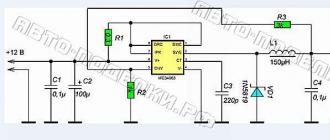
Which is exactly what we need. As you know, the power supply of the on-board network is 12 V, and the charger needs 5 V. Therefore, on the basis of this microcircuit, we will assemble a voltage converter from 12 V to 5 V. A schematic diagram of the future device is shown below.

The output voltage rating is set by the values of the resistors R2 and R3. For the required value of 5 V, it is necessary to set R2=1 kΩ, R3=3 kΩ. The formula for determining the output voltage value is given below, so if you need to set the output to a different voltage, you can use it to calculate.

In principle, you can make a universal adapter if you put a variable in place of R3 and unscrew the required value. The only thing that should be done before this is a calculation in order to understand in what range its values \u200b\u200bshould be.
Resistor R1 plays the role of a current limiter, when R1 is set to 0.3 Ohm, exceeding the output current by more than 500 mA turns off the device, reducing the resistance value will increase the cutoff current limit.


Capacitor C3 sets the frequency of the converter, the remaining capacitors are filtering. The inductor also acts as a filter, it is calculated for a current of 1 A. 1N5819 was chosen as a diode, but a domestic analogue is also quite suitable.


The adapter is assembled on the basis of the Z-43 case, its size is quite enough to compactly place the entire element base. At the input we put the plug in the cigarette lighter at the output USB connector - done!


Buy ready made charging to phone not interested). Craft do it yourself much more interesting, especially since such a simple and reliable device has already been tested. Yes, and she did not want to occupy the cigarette lighter. I learned about such a thing as KR142EN5A. Advantages of this chip:
- Permissible output current 1A
- No external components required
- Internal thermal protection
- Output transistor protection
- Internal short circuit current limitation
The input voltage is up to 20 V, and the output is always 5 V. Actually, which is what is needed in order to stably charge the phone's battery. There is nothing difficult to assemble. We solder four wires to the circuit (solder two leads to the central leg - this will be the “mass”). The left terminal is the “+” input, the central one is ground, the right output is “+”.
I had an old broken charger, I cut off the plug from it and soldered it to a microcircuit.” +” plug to “+” at the output of KR142EN5A, and “-” plug to circuit ground. It turns out a mass wire common to the input and output. In the car, I dragged the wires to a convenient place where the phone always lies, connected to a permanent connection through a button). I pressed the button, plugged the plug into the phone and started charging). Here are the pics I post...


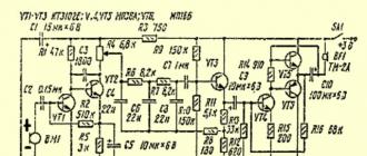
But then I had to improve the circuit a little, since the familiar “minds” recommended putting two 1000 microfarad capacitors. It turned out here is such a scheme. I recommend installing the conduits right away, although everything worked without them ... And put the microcircuit itself on a small radiator (to be sure)


Hello Habra gentlemen and Habra ladies!
I think some of you are familiar with the situation:
“Car, traffic jam, N-th hour of driving. The communicator with the navigator running for the 3rd time beeps about the end of the charge, despite the fact that it is connected to charging all the time. And you, as an evil, are absolutely not oriented in this part of the city.
Next, I will talk about how, with moderately direct hands, a small set of tools and a little money, build a universal (suitable for charging with a rated current, both Apple and all other devices), USB car charging for your gadgets.
WARNING: There are a lot of photos under the cut, some work, no LUT and no happy ending (not yet).
Author, what for all this?
Some time ago, the story described in the prologue happened to me, a Chinese usb twin, absolutely shamelessly let my smart phone run out during navigation, out of the declared 500mA it gave out about 350 for both sockets. I must say I was very angry. Well, okay - I'm a fool myself, I decided, and on the same day, in the evening, a 2A car charger was ordered on eBay, which rested in the depths of the Chinese-Israeli mail. By a lucky chance, I had a DC-DC step down converter with an output current of up to 3 A lying around, and I decided to assemble a reliable and universal car charger on its basis.A little about chargers.
Most of the chargers that are on the market, I would divide into four types:
1. Apple - sharpened for Apple-devices, equipped with a little charging trick.
2. Ordinary - focused on most gadgets, for which shorted DATA + and DATA- are enough to consume the rated charge current (the one that is declared on the charger of your gadget).
3. Stupid - in which DATA + and DATA- hang in the air. In this regard, your device decides that it is a USB hub or a computer and does not consume more than 500 mA, which negatively affects the charge rate or even in the absence of it under load.
4. Cunning%!$&e - since they have a microcontroller installed inside, which tells the device that something from the category of what the notorious Kipling hero told animals - “We are of the same blood, you and me”, checks the originality of the charge. For all other devices, they are the third type of memory.
The last two options, for obvious reasons, I consider not interesting and even harmful, so we will focus on the first two. Since our charging should be able to charge both apple and all other gadgets, we use two USB outputs, one will be focused on Apple devices, the second on all the rest. I will only note that if you mistakenly connect the gadget to a USB socket not intended for it, nothing terrible will happen, it will simply take the same notorious 500mA.
So, the goal: "After working a little with your hands, get a universal charger for the car."
What do we need
1. To begin with, let's deal with the charge current, usually it is 1A for smartphones and about 2 Amperes for tablets (by the way, my Nexus 7, for some reason, does not take more than 1.2A from its own charge). In total, for the simultaneous charging of an average tablet and smartphone, we need a current of 3A. So the DC-DC converter that I have available is quite suitable. I must admit that a 4A or 5A converter would be better suited for these purposes, in order to have enough current for 2 tablets, but I did not find compact and inexpensive solutions, and even time was running out.So I used what was:
Input voltage: 4-35V.
Output voltage: 1.23-30V (adjustable by potentiometer).
Maximum output current: 3A.
Type: Step Down Buck Converter.

2. USB socket, I used a double one that I soldered from an old USB hub.

You can also use regular sockets from a USB extension cable.
3. Breadboard. In order to solder a USB socket to something and assemble a simple charging circuit for Apple.

4. Resistors or resistances, as you like, and one LED. Only 5 pieces, 75 kOhm, 43 kOhm, 2 with a nominal value of 50 kOhm and one at 70 Ohm. On the first 4, the Apple charging circuit is being built, I used 70 Ohms to limit the current on the LED.
5. Body. I found a Mag-Lite flashlight case in the bins of my homeland. In general, a black toothbrush case would be ideal, but I did not find one.

6. Soldering iron, rosin, solder, wire cutters, drill and an hour of free time.
We collect charging
1. First of all, I shorted the DATA + and DATA- pins to each other on one of the sockets:

* I apologize for the harshness, I got up early and the body wanted to sleep, and the brain continued the experiment.
This will be our outlet for non-apple gadgets.
2. We cut off the size of the breadboard we need and mark and drill holes in it for the mounting legs of the USB socket, at the same time checking that the contact legs match the holes in the board.

3. We insert the socket, fix it and solder it to the breadboard. We close the + 5V contacts of the first (1) and second (5) sockets with each other, we do the same with the GND contacts (4 and 8).

The photo is for clarification only, the contacts are already soldered on the breadboard
4. Solder the following circuit to the remaining two contacts DATA+ and DATA-:

To observe the polarity, we use the USB pinout:

I got it like this:

Do not forget to adjust the output voltage, using a screwdriver and a voltmeter, set 5 - 5.1V.
I also decided to add an indication to the USB power circuit, in parallel to + 5V and GND I soldered yellow ice with a 70 Ohm resistor to limit the current.
A convincing request to people with a fine mental organization and other lovers of beauty: "Do not look at the following picture, because the soldering is crooked."
I am brave!

5. We fix the converter board on our breadboard. I did this with the help of legs from all the same resistors, soldering them into the contact holes on the converter board and on the breadboard.

6. Solder the outputs of the converter to the corresponding inputs on the USB socket. Observe polarity!
7. We take the case, mark and drill holes for mounting our board, mark and cut out a place for a USB socket and add holes for ventilation opposite the converter chip.

We fasten the breadboard with bolts to the case and get this box:

In Machine it looks like this:

Tests
Next, I decided to check whether my devices will really consider that they are being charged from their native charger. And at the same time measure the currents.Power is provided by the PSU from an old 24V 3.3A printer.
I measured the current before going to USB.
Looking ahead, I’ll say that all the devices I have recognized charging.
To USB socket number one (which is designed for different gadgets) I connected:
HTC Sensation, HTC Wildfire S, Nokia E72, Nexus 7, Samsung Galaxy ACE2.
For the Sensation and Nexus 7, I checked the charge times, starting at 1% and charging up to 100%.
The smartphone was charged in 1 hour 43 minutes (Anker 1900 mAh battery), I should note that it takes about 2 hours to charge from a standard charge.
The tablet was charged in 3 hours 33 minutes, which is half an hour longer than charging from the network (I only charged one device at a time).

In order for both Android devices to take the maximum from charging, I had to solder a small adapter (which connected to apple USB), HTC Sensation is connected to it.
I connected to USB socket number two: Ipod Nano, Ipod Touch 4G, Iphone 4S, Ipad 2. Since Nano is ridiculous to charge with such a thing - it took a maximum of 200 mA from me, checked Touch 4g and iPad. Ipod charged 1 hour 17 minutes from zero to 100% (albeit with IPAD 2). iPad 2 took 4 hours and 46 minutes to charge (one).

As you can see, the Iphone 4S consumes its rated current with pleasure.

By the way, Ipad 2 surprised me, it absolutely did not shy away from circuits with shorted data contacts and consumed absolutely the same currents as from the socket intended for it.
Charging process and conclusions
To begin with, let me remind you that all devices that use lithium batteries have a charge controller available. It works according to the following scheme:
The graph is averaged and may vary for different devices.
As you can see from the graph, at the beginning of the charging cycle, the controller allows charging with the maximum allowable current for your device and gradually reduces the current. The charge level is determined by the voltage, the controllers also monitor the temperature and turn off charging at high values of the latter. Charge controllers can be located in the device itself, in the battery or in the charger (very rarely).
You can read more about charging lithium cells.
Actually, here we come to the point why this topic is called: "Attempt number one." The fact is that the maximum that I managed to squeeze out of the charge is: 1.77A

Well, the reason, in my opinion, is not the optimally selected inductor, which in turn prevents the Buck-converter from delivering its maximum current. I thought to replace it, but I don’t have a tool for soldering SMD and it’s not expected in the near future. This is not a fault of the ebay board designers, this is just a feature of this circuit as it caters for different input and output voltages. Under such conditions, it is simply impossible to deliver the maximum current over the entire voltage range.
As a result, I got a device that can charge two smartphones at the same time or one tablet in a car in reasonable time.
In connection with the foregoing, it was decided to leave this charge as it is and assemble a new one, completely with your own hands, based on a more powerful LM2678 converter,
which in the future will be able to “feed” two tablets and a smartphone at the same time (5A output). But more on that next time!
P.S.:
1. The text may contain punctuation, grammatical and semantic errors, please report them in a personal message.
2. Thoughts, ideas, technical corrections and CC from more experienced comrades - on the contrary, they are welcome in the comments.
3. I apologize for possible technical inaccuracies, because Until recently, I did not deal with electronics and circuitry.
Thank you for your attention, good luck and inexhaustible optimism!
The MC34063 is a popular IC for designing small circuits of transformerless voltage converters. It is universal, because on its basis it is possible to make step-up, step-down and inverting DC-DC voltage converters. The range of input and output voltages makes it easy to assemble on the basis of this microcircuit a number of voltage converters at minimal cost, which are indispensable in everyday life.
Of course, all these designs can be bought in China, ready-made, but we won’t talk about this today, you can buy everything in China, but it’s more interesting to do it yourself.
We will consider the design of a step-down voltage converter, the input of which can be supplied with voltage from 5/6 to 40 Volts, while the output voltage will always be kept stable, at the level of 5 Volts. from 5 Volts all mobile phones, tablets, some players and players are charged.
The microcircuit is widely popular among radio amateurs for the very reason that it costs a penny and contains minimal strapping.
Inductor, rectifier diode (Schottky) and several passive components. The output voltage may be different, there are a lot of programs and formulas for calculating inverters on this chip. The output voltage depends on the ratio of resistors R3/R2.

The diode, in principle, is also not critical and you can take the usual pulse ones, you can from the FR / UF / HER / SF line, etc.
The diode is needed with a current higher than 1.5 amperes, 3 is better, since the output current from the microcircuit can reach up to 1.5 amperes. The inductor itself is wound on a ferrite dumbbell, a ring is also possible, the winding is wound with a wire of 0.6-0.8 mm and consists of 15-20 turns. You can take a ready-made choke from some computer power supplies.

Capacitor C1 is responsible for the operating frequency of the generator built into the chip, it is advised to run the chip at frequencies of 40-60 kHz.

By the way, single-cycle transformer voltage converters are also implemented on this microcircuit to obtain a wider range of output voltage and provide galvanic isolation. At the same time, the power can also be increased, because in this case the output of the microcircuit is amplified by a powerful transistor.
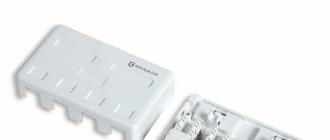
Many modern cars have modules with multiple USB outputs for power. By and large, several USB sockets are necessary in any car, because so often you have to charge your phone, tablet, camera, and you also need to connect a navigator and a recorder.
It's high time to make a neat panel with USB sockets in the car. And it’s not at all difficult and not expensive to assemble it yourself, even on.
To assemble a USB power supply you will need at least:
- microchip voltage stabilizer at 5 V;
- two capacitors: both for 25 V or only one and the other for 10 V (capacitor capacitance values depend on the selected stabilizer, and will be determined later);
- 1 A semiconductor diode;
- socket types: 1USB-A or 2USB-A;
- connecting wires of small cross section - no more than 0.5 mm.kv.
Microchip stabilizers USB power supply assembly voltages are preferred as they are:
- capable of operating within a wide range of input voltages of 7 - 20 V;
- have an overcurrent protection system;
- are equipped with an overheating protection system, which, when the microcircuit crystal is heated, limits the output current.
One USB connector can be powered from the 78L05 stabilizer: Imax = 0.1 A, Pmax = 0.5 W, TO-92 case.
Two or more USB connectors must be connected to power from 78M05 or 7805 stabilizers.
The 78M05 microcircuit has the following characteristics: Imax \u003d 0.5 A, Pmax \u003d 7.5 W, TO-202 or TO-220 case.
Chip 7805: Imax = 1.5 A, Pmax = 10 W, TO-220 package.
The 78 series stabilizers are made in a package that makes them look like transistors.
The pinout for microcircuits 78M05 and 7805 is as follows:
- the first output on the left is the input (if you look at the case from the side of the marking);
- medium - general;
- the third is the exit.
The 78L05 microcircuits have the reverse pinout than the 78M05 and 7805 microcircuits.
When assembling the circuit, you need to take into account that the common output of the 78M05 and 7805 microcircuits is connected to their metal heat sink, therefore, when mounting the stabilizer on the radiator, do not close the rest of the circuit elements. And it is still desirable to screw the microcircuit to the radiator, because the stabilizer will work better in this case (remember that microcircuit stabilizers limit the current on the load when overheated).
semiconductor diode needed to limit current surges when switches or relay contacts are turned on, through which a stabilization circuit can be connected.
Capacitors you need to set 10 microfarads, and not 47 microfarads, if you use a less powerful 78L05 stabilizer in the circuit, and not 78M05 and 7805 microcircuits. In terms of voltage, the capacitors, as mentioned earlier, must be selected for 25 V each, or a capacitor at the output can be set to 10 V.
Light-emitting diode it is not necessary as a power indicator, but it helps to visually determine the presence of voltage at the output and the health of the stabilization circuit.
Resistor it is not necessary to set it to 160 ohms, because with such a quenching resistance, the LED may shine too brightly. The quenching resistor can be selected with resistances: 270 Ohm, 300 Ohm, 470 Ohm.
Having assembled the voltage stabilization circuit, you need to connect it to the USB socket: plus 5 V output - to the plus contact of the USB supply voltage; common output to - common contact of the connector.
The pinout for the USB sockets is as follows:
- the first contact on the left is common (if you look at the connector contacts from above);
- the second - plus the data bus;
- the third is plus data buses;
- the fourth - plus supply voltage.
Of course, you will not transfer any data using the USB socket as a power source, so do not pay attention to the second and third pins of the connector.
Where to install USB power sockets in the car is a personal decision for each master. But as a recommendation, we can say that it is convenient to place several connectors, along with the assembled circuit, on a separate panel cut from a plastic or aluminum plate. Also on this small console, you can install a small switch that will turn off the voltage at the input of the stabilization circuit. A ready-made socket with USB connectors is very easy to install in a convenient place in the car.
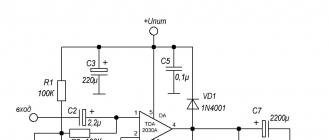
A simple monoblock car amplifier on the TDA1560Q  Automotive chokeless PSU on IRS2153 for laptops and mobile phones