Start.
It is often necessary to find in a heap of wires where which one goes, find out the continuity of the circuit, check if there is a short circuit or an open circuit, you also often need to find out the integrity of the p-n junction of diodes, transistors and other semiconductors, such a tool as a dial tone will help us with this. It will undoubtedly be useful to both electricians and electronics. The fact is that it is not always convenient to use the dial mode in a multimeter, and some of them do not have this function at all, so such a simple dial tone will solve this problem.

The ringing is very practical, its tone depends on the resistance of the tested section of the circuit. The higher the resistance, the less frequent the clicks, respectively, with a small resistance of clicks, there will be a lot of clicks and they will be heard as a squeak, the tone of which can be adjusted by denominations: That is, on a ready-made board with soldered components, you can easily find a short circuit, and we will hear pn junctions not like KZ, the tonality will be different. And if you get used to it a little, then by the sound you can easily tell where the emitter is at the transistor, and where the collector is (the second has more clicks).
Frame.
The body is also very important, it will determine how pleasant it will be to use the device, nevertheless, aesthetics is important. In addition, it will protect the scarf and the battery from the harsh conditions of everyday life of a person working with electricity.
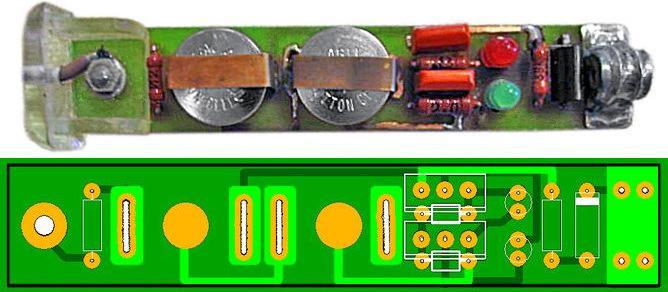
I took the case from an ATB marker, one AA element ideally fits into it and there is still room for the board, and it looks good for these purposes.
As probes for heaps of copper wire in enamel and a cylindrical piece of copper, namely the old soldering iron tip, this non-ferrous metal has low resistance and more or less well tolerates O2, especially with solder :) On the board itself, the tip is fixed with molten tin in a certain area of copper.

In the picture you can see how the dialing is arranged from the inside, first there is a probe that departs from the board, then the dialing board itself, then the battery / accumulator, which is tightly fixed with a "plug".
There is also a speaker here - this is an indication element, for loud sound reproduction there are many holes through which it sways air. (he's not drawn!)
Components and replacements.
The values of the parameters of all the parts used in this circuit are not critical and can vary, for example, there is no 51k resistor, but there is 47k - then feel free to put it. All transistors - any, the main thing is that the structure coincides (3 - NPN, 1 - PNP).
Marking: BC847– 1 G , BC857 –3 F (and N side).
Notifiers.

The speaker, of course, is taken miniature - such as in headphones. Its impedance is usually 16 ohms, and the volume is quite sufficient. I had a speaker from an old Nokia 6303Ai, a very good phone should be noted. I glued it to the back of the board with hot glue, it acted as a resonator.

If you work in a place where it is very noisy, then you should put an LED in parallel with the sound emitter, which will serve as a light indication.
Food.
Continuity power is a 1.5 Volt finger battery, if you increase this value, then it will be possible to check the LEDs, besides, the sound volume will increase significantly. However, in this case, the high voltage can damage some sensitive radio components.
Add sensitivity.

Want super mega sensitivity? Then disconnect the electrolytic capacitor C1. Now, if we just touch the probes of the device, then it will already begin to react violently to this. I don't know why, but if you want such a frantic mode, then put a micro-button on one of the capacitor terminals.

And it's better for you in general the same, but slightly modified circuit, so we get two modes: very low sensitivity and super-sensitivity up to 120 MΩ. You can easily switch between them using the S1 and S2 buttons.
Photo.


(almost finished board, but without speaker and probes)

(finished board with probe and spring, side view)

In many cases, it is not at all necessary to measure the resistance of a particular part. It is only important to make sure, say, that a circuit is intact, that it is isolated from another, that a diode or a transformer winding is in good working order, etc. In such situations, instead of a dial gauge, a probe is used - its simplest substitute. The probe can be, for example, an incandescent lamp or headset connected in series with the battery. Touching the remaining terminals of the lamp (or phone) and the battery of the tested circuits by the glow of the lamp or clicks in the phone, it is easy to determine the integrity of the circuits or to judge their resistance. But, of course, the scope of use of such probes is limited, therefore, in the arsenal of the measuring laboratory of a novice radio amateur, it is desirable to have more advanced designs. We will get acquainted with some of them.
Before proceeding with the establishment of the assembled structure, it is necessary, as they usually say, to "ring" its installation, that is, to check the correctness of all connections in accordance with the schematic diagram. Often, radio amateurs use a relatively bulky device for these purposes - an ohmmeter or an avometer, operating in the resistance measurement mode. But often such a device is not needed, it can be replaced by a compact probe, whose task is to signal the integrity of a particular circuit. Such probes are especially convenient when “ringing” multi-wire harnesses and cables. One of the schemes of such a device is shown in Fig. P-22. It has only three low-power transistors, two resistors, an LED and a power supply.
In the initial state, all transistors are closed, since there is no bias voltage at their bases relative to the emitters. If you connect the leads "to the electrode" and "to the terminal", a current will flow in the base circuit of the transistor VT1, the strength of which depends on the resistance of the resistor R1. The transistor will open, and a voltage drop will appear across its collector load - resistor R2. As a result, transistors VT2 and VT3 will also open, and current will flow through the HL1 LED. The LED will flash, which will serve as a signal that the circuit under test is in good order.
The peculiarity of the probe is its high sensitivity and relatively low current (no more than 0.3 mA) flowing through the measured circuit. This made it possible to make the probe somewhat unusual: all its parts are mounted in a small plastic case (Fig. P-23), which is attached to a strap (or bracelet) from a wristwatch. From the bottom to the strap (opposite the case), a metal plate-electrode is attached, connected to a resistor R1. When the strap is fastened on the arm, the electrode is pressed against it. Now the fingers of the hand will act as the probe of the probe. When using a bracelet, no additional electrode plate is needed - the output of the resistor R1 is connected to the bracelet.

The probe clamp is connected, for example, to one of the ends of the conductor, which must be found in the bundle or "ring out" in the installation. Touching with your fingers alternately the ends of the conductors on the other side of the bundle, they find the desired conductor by the appearance of the LED glow. In this case, not only the resistance of the conductor is included between the probe and the clamp, but also the resistance of a part of the hand. Nevertheless, there is enough current passing through this circuit for the probe to "trigger" and the LED to flash.
Transistor VT1 can be any of the KT315 series with a static coefficient (or just a coefficient - so for brevity we will write further) current transfer of at least 50, VT2 and VT3 are others, except for those indicated on the diagram, the corresponding structure and with a transfer coefficient of at least 60 ( VT2) and 20 (VT3).
The AL102A LED is economical (consumes a current of about 5 mA), but has a low brightness. If it is not enough for your purposes, install the AL102B LED. But the current consumption will increase in this case several times (of course, only at the time of indication).
Power source - two batteries D-0.06 or D-0.1, connected in series. There is no power switch in the probe, since in the initial state (when the base circuit of the first transistor is open) the transistors are closed, and the consumption current is negligible - it is commensurate with the self-discharge current of the power source.
The probe can generally be assembled on transistors of the same structure, for example, according to the one shown in Fig. P-24 scheme. True, it contains slightly more details compared to the previous design, but its input circuit is protected from external electromagnetic fields, which sometimes lead to false flashing of the LED. This probe employs silicon transistors of the KT315 series, which are characterized by a low reverse collector junction current over a wide temperature range. When using transistors with a current transfer ratio of 25..30, the input resistance of the probe is 10 ... ... 25 MΩ. An increase in the input impedance is inappropriate due to an increase in the probability of false indication by external pickups and extraneous conductivities.
A sufficiently large input resistance is achieved by using a composite emitter follower (transistors VT1 and VT2).
Capacitor C1 creates deep negative AC feedback, eliminating false indications from external pickups.
As in the previous case, in the initial mode, the device practically does not consume energy, since the resistance of the HL1VT3 circuit connected in parallel to the power source in the closed state of the transistor is 0.5 ... 1 MΩ. The current consumption in the indication mode does not exceed 6 mA.

The input impedance of the device can be corrected by selecting the resistor R2, having previously connected a chain of resistors with a total resistance of 10 ... ... 25 MΩ to the input and achieving the minimum brightness of the LED.
But what if there is no LED? Then, instead of it, you can use in both versions a small-sized incandescent lamp for a voltage of 2.5 V and a current consumption of 0.068 A (for example, an MH 2.5-0.068 lamp). True, in this case, you will have to reduce the resistance of the resistor R1 to about 10 kΩ and choose it more accurately according to the brightness of the lamp glow with closed input conductors.
Probes with sound indication can be of no less interest to radio amateurs. A diagram of one of them, attached to the hand with a bracelet, is shown in Fig. P-25. It consists of a sensitive electronic key on transistors VT1, VT4 and an AF generator assembled on transistors VT2, VT3 and a miniature telephone BF1. The oscillation frequency of the generator is equal to the mechanical resonance frequency of the telephone. Capacitor C1 reduces the influence of alternating current pickups on the operation of the indicator. Resistor R2 limits the collector current of transistor VT1, and hence the emitter junction current of transistor VT4. Resistor R4 sets the highest volume of the phone sound, resistor R5 affects the reliability of the generator when the supply voltage changes.

The sound emitter BF1 can be any miniature telephone (for example, TM-2) with a resistance from 16 to 150 Ohm. The power source is a D-0.06 battery or an RC53 element. Transistors - any silicon of the appropriate structure, with a current transfer coefficient of at least 100, with a collector reverse current of no more than 1 μA.
Probe parts can be mounted on an insulating strip or board made of single-sided foil-clad fiberglass. The bar (or board) is placed, for example, in a metal case in the form of a wristwatch, to which a metal bracelet is connected. A hole is cut out in the housing cover opposite the emitter, and a miniature socket of the XT1 connector is fixed on the side wall, into which an extension conductor with an XP1 probe (it may be a crocodile clip) is inserted at the end.
A slightly different probe circuit is shown in Fig. P-26. It uses both silicon and germanium transistors. Moreover, it is not at all necessary to make the design small, the indicator itself can be assembled in a small box, and the bracelet and probe can be connected to it with flexible conductors.
The capacitor C2 shunts the electronic switch on the alternating current, and the capacitor. SZ - power source.
It is advisable to select transistor VT1 with a current transfer ratio of at least 120 and a collector reverse current of less than 5 μA, and VT2 with a transfer ratio of at least 50, VT3 and VT4 - at least 20 (and a collector reverse current of no more than 10 μA). The sound emitter BF1 is a DEM-4 capsule (or similar) with a resistance of 60 ... 130 Ohm.
Probes with sound indication consume slightly more current than the previous one, so it is advisable to disconnect the power supply during long interruptions in operation.

B.S. Ivanov. The beginner radio amateur's encyclopedia
"CONTROL" and "CALL" for ELECTRICIAN.
When checking the electrical circuit of the machine in noisy workshops, it is not very convenient to use measuring instruments, you have to simultaneously hold the probes of the device, look at its readings and also click the operating mode switch. And although the "RULES FOR SAFE OPERATION OF CONSUMER ELECTRICAL INSTALLATIONS" prohibit the use of test lamps, electricians often use a simple test lamp to check the health of electrical circuits, which is used as a convenient and multifunctional "device".
Although, the point is, in general, not in the light bulb, but in who is holding it - you can screw up both with a voltage indicator and with a trusted device, if it is in the hands of an irresponsible employee or someone who does not know how to handle it properly.
But the convenience with the correct use of the "control" speaks for itself:
By the glow of the lamp, you can visually assess the magnitude of the applied voltage;
The glow of an incandescent lamp is clearly visible in bright light;
Due to the low input impedance, it does not give false alarms from induced voltage ("pickup") and "through the load";
Allows you to check the protective grounding circuits, the operation (or malfunction) of the RCD, and everything else can be used as a portable light source.
For safe use, the test lamp should be structurally enclosed in a case made of insulating material, transparent or with a slot for the passage of a light signal. Conductors should be flexible, reliably insulated, no more than 0.5 m long, to exclude the possibility of short circuits when passing them in a common lead-through, leave the armature in different holes, and at the free ends have rigid electrodes protected by insulated handles, the length of the bare end of the electrode should not exceed 10 - 20 mm.
To make a simple and easy-to-repeat version of "control": we take two 220V 15W lamps for the refrigerator, solder them in series with each other, as conductors, you can use probes from a multimeter with plastic holders at the ends, the wires in which it is desirable to replace with better quality. The flanges on these probes prevent fingers from getting into the open ends of the probes and conductive parts of the installations. Then we place both lamps in a suitable case (for example, in a piece of transparent hose) and bring the wires out. 
In the process of checking the integrity of the wiring, the rules of electrical safety must be strictly observed, the "control" must be suspended on the wires; when checking the closeness to the floor, it must be moved away from you as far as possible.
PROBE - INDICATOR.
In the same cases (conditions), when it is more convenient to use "control" and not a device, that is, in simple circuits for a preliminary assessment of the functioning of units during the repair and adjustment of electrical devices and electronic devices, where measurement accuracy is not needed. An indicator probe can often be useful to determine in the circuit under test:
Availability of alternating or direct voltage from 12 to 400V,
Phase wire in AC circuits,
Approximate voltage value,
Polarity of DC circuits,
To make a "continuity" of the integrity of circuits, including the windings of electric motors, starters, transformers, contacts,
Check the health of diodes, transistors, thyristors, etc.
Various indicators with light and sound indication, which are simple and reliable in operation, cope well with these requirements.
EASY PROBE, equipped with two LEDs and a neon lamp, allows you to check the presence of a phase in the network, detect a short circuit and the presence of resistance in the circuit. With its help, you can check the coils of magnetic starters and relays for an open, ring the ends of chokes, motors, deal with the terminals of multi-winding transformers, check rectifier diodes and much more.
The probe is powered by a battery "Krona" or any other similar type with a voltage of 9V, the current consumption when the probes are closed is no more than 110 mA, when the probes are open, no energy is consumed, which makes it possible to do without a power switch and a mode switch.
The device remains operational when the supply voltage drops to 4V, with a discharged battery (below 4V) it can work as an indicator of the mains voltage. 

When a circuit with a resistance from zero to 150 Ohm is dialed, the red and yellow LEDs light up, with a circuit resistance from 150 Ohm to 50 kOhm, only the yellow LED is on. When a 220-380V mains voltage is applied to the probes, a neon lamp lights up, and the LEDs flicker slightly.
The probe is made on three transistors, in the initial state all transistors are closed, since the probe probes are open. When the probes are closed, the voltage of positive polarity through the diode VD1 and the resistor R5 enters the gate of the field-effect transistor V1, which opens and through the base-emitter transition of the transistor V3 is connected to the negative wire of the power source. LED VD2 flashes. The V3 transistor also opens, the VD4 LED lights up. When connected to resistance probes in the range of 150 Ohm-50 kOhm, the VD2 LED goes out, since it is shunted by the resistor R2, the resistance of which is relatively less than the measured one, and the voltage across it is not enough for its glow. When the mains voltage is applied to the probes, the neon lamp HL1 flashes.
A half-wave mains voltage rectifier is assembled on the VD1 diode. When the voltage on the Zener diode VD3 (12V) is reached, the transistor V2 opens and thereby locks the field-effect transistor V1. LEDs flicker slightly.  DETAILS: Field-effect transistor TSF5N60M will be replaced by 2SK1365, 2SK1338 from pulse chargers of a video camera, etc. Transistors V2, V3 are interchangeable with 13003A from an energy-saving lamp. Zener diode D814D, KS515A or similar with a stabilization voltage of 12-18V. Small resistors 0.125 W. Neon lamp from a screwdriver indicator. Any LEDs, red and yellow. Any rectifier diode with a current of at least 0.3A and a reverse voltage of more than 600V, for example: 1N5399, KD281N.
When properly mounted, the probe starts working immediately after power is applied. During adjustment, the range of 0-150 Ohm can be shifted to one side or the other by selecting the resistor R2. The upper limit of the 150 ohm-50 k ohm range depends on the V3 transistor instance.
The probe is housed in a suitable housing of insulating material, such as a mobile phone charger housing. A pin-probe is removed from the front, and a wire with good insulation with a pin (or crocodile) is removed from the end of the case.
UNIVERSAL INDICATOR ON THE MICROCIRCUIT.
Allows you to determine:
"Phase" wire in power circuits and electrical network;
The presence of a constant voltage in the range of 10 ... 120V;
The presence of alternating voltage in the range of 10 ... 240V;
Signal presence in telephone networks;
Signal presence in the broadcasting network;
Serviceability of fuses;
Serviceability of resistors with a resistance of 0 ... 100kΩ;
Serviceability of capacitors with a capacity of 0.05 ... 20 μF;
Serviceability of transitions of silicon diodes and transistors;
Availability of TTL and CMOS pulses up to 10 kHz.
In addition, you can find the ends of the wires in the installation harness, both with the help of the supply voltage, and without it. 
Schematic diagram of the indicator.
When the probes are open, the voltage at pin 1 of the DD1.1 element is determined by the voltage drop across the series-connected elements HL1, HL2, R3 and R4 is not enough to trigger the DD1.1 trigger. The multivibrator on DD1.1, DD1.2 does not work, the HL4 LED is off. In this mode, the current consumed from the GB1 battery does not exceed 2 ... 3 μA, which allows the indicator to do without a power switch.
In the mode of "continuity" of the circuits when the probes are closed, the input current of the circuit passes through the resistors R1-R4, the voltage at pin 1 of the DD1.1 element rises and starts the multivibrator on the DD1.1, DD1.2 elements. From the multivibrator, pulses with an oscillation frequency of about 3 kHz are fed to the DD1.3 element - a buffer amplifier for the HL4 LED. In addition to the light indication of the multivibrator operation, the BF1 emitter also produces an audible alarm, which is connected between two inverters - DD1.4 and DD1.1 to increase the signal amplitude.
Applying a constant voltage of 10 ... 120V to the indicator input causes the LEDs HL1, HL2 to light up, and if the polarity is reversed at the inputs, HL3. With an increase in the controlled voltage, the brightness of their glow, visible to the eye already at 10V, increases. When the indicator controls an alternating voltage of 10 ... 120V with a frequency of 50 Hz, the glow of all LEDs HL1-HL4 is visible, and the presence of a voltage with a frequency of 50 Hz is noticeable by ear due to the characteristic tone modulation of 3 kHz. Moreover, auditory control turns out to be more sensitive, since this modulation is noticeable already at voltages above 1.5V.
When a serviceable oxide capacitor with a capacity of 20 μF is connected to the probes (in accordance with the polarity of the voltage on the probes), it is charged along the R1 - R4 circuit. In this case, the duration of the tone signal is proportional to the capacitance of the tested capacitor - about 2 seconds per microfarad.
Checking the health of semiconductor diodes and transistor transitions does not require explanation. True, the reverse current of the pn junction of a diode or transistor of more than 2 μA can cause an audible alarm for any polarity of switching on a semiconductor junction.
TTL and CMOS logic levels are indicated with inversion, i.e. a high level corresponds to the absence of the HL4 LED and tone signal, and a low level means that the LED turns on and a tone signal.
The advantage of the indicator is that the test voltage on its probes, which does not exceed 4.5V at a current of 3 μA, is safe even for field and microwave devices.
The use of two resistors R1 and R2 in the circuit increases the safety of working with the indicator, the values of these resistors (R1 and R2) are selected depending on the limit value applied to the input of the controlled voltage. So to control the input voltage up to 380V, with a current through the HL1-HL3 LEDs of about 10 mA, the resistance of the resistors R1 and R2 should be increased to 20 kOhm!
When connecting to working equipment, it must be borne in mind that the internal resistance of the indicator is only 24 kOhm.
It is recommended to use LEDs HL2 - AL307A or similar ones with red glow in the design, and HL4 - with red or yellow glow (for example, AL307D). HL1, HL3 - AL307G or similar green glow. Resistors R1, R2 - MLT-2, other resistors and capacitors - any small-sized. 

BF1 - any piezoceramic emitter, three alkaline "button" cells with a voltage of 1.5V used in calculators, key chains, flashlights, etc. are used as the G1 battery.
The design and installation of elements largely depends on the housing used; you can make a particularly small-sized structure using a microcircuit and parts for surface mounting. 
Drawing of a possible board option.
The board is designed for the installation of MLT resistors and capacitors KM-6 (C1) and K10-17. LEDs are placed in an easy-to-observe place on the front side of the case.
It is advisable to make the positive terminal of the input circuit of the device in the form of a probe, and the negative terminal in the form of a flexible wire with a crocodile clip at the end.
If the parts are in good condition, adjustment of the device is usually not required. The current consumption with open inputs should not be more than 4 μA. If, when connecting the power supply battery, the HL4 indicator glows even when the terminals are open, you should select the HL1, HL2 LEDs with a high threshold voltage or HL3 with a lower reverse current of the pn junction. You can increase the volume of the audible alarm by selecting a resistor R6 or capacitor C1, adjusting the generator frequency closer to the frequency most efficiently emitted by the BF1 converter.
THE FOLLOWING DIAGRAM allows you to evaluate the magnitude and sign of the voltage ("+", "-", "~") within several limits: 36V,> 36V,> 110V,> 220V, 380V, and you can also ring out electrical circuits, contacts and relay coils, starters, incandescent lamps, pn junctions, LEDs, etc. almost everything that an electrician most often encounters in the course of his work (with the exception of measuring current).

In the diagram, switches SA1 and SA2 are shown in an unpressed state, i.e. in the position of the voltmeter, the voltage value can be judged by the number of LEDs lit in the VD3 ... VD6 line, and the VD1 and VD2 LEDs show the polarity, the approximate (recommended) arrangement of elements on the front panel and in the case is shown in the figure. Resistor R2 must be made of two or three identical resistors connected in series with a total resistance of 27 ... 30 kOhm. Pressing the SA2 switch turns the probe into a classic continuity, i.e. battery plus light bulb. If you press both switches SA1 and SA2, you can check circuits in two resistance ranges: - the first range - from 1 MΩ and above to ~ 1.5 kΩ (VD15 is on); - the second range is from 1 kOhm to 0 (VD15 and VD16 are on). Zener diodes can be used small-sized imported. Batteries (type "316") last a year or more.
The probe can be supplemented with a "phase" indicator (HL2, R8, contact E1), which will be very useful when repairing lighting.
The housing options depend on the dimensions of the parts used. It is better to put the switches on different sides of the board, then when using it for the first time there will be fewer errors. The most common error is that, not making sure that there is no voltage in any circuit, the user presses the switches for continuity, while the HL1 lamp burns out, acting in this case as a fuse. Thus, when working on non-disconnected circuits, one must be careful and attentive, which is what the safety rules require.
ELECTRIC INSTALLER'S PROBE.
Before starting to work with the probe, the circuit of which is shown in the following figure, it is necessary to charge the storage capacitor C1. To do this, simply insert the probe probes into a power outlet for a few seconds.
At the same time, LEDs LED2 - LED6 light up, indicating that the probe is in good working order and there is a voltage of 220V in the network. 

During operation, the lighting of the LEDs indicates the presence of the following voltages:
LED4 - 36V;
LED3 - 110V;
LED2 - 220V;
LED1 - 380V.
LED5 is used for continuity (about a minute of continuous light), and LED6 indicates voltage polarity (when measuring voltage in DC circuits).
It is necessary to pay attention to the fact that this is still a probe, not a measuring device, so the threshold for switching on the LEDs is not very clear, but quite sufficient. For example, at 127V, LED4 and LED3 are on, and LED2 and LED1 are off. It may be necessary to select the resistances R1, R2 and R5 for a more accurate indication when setting up.
The main elements of the probe are mounted on a printed circuit board, to reduce the thickness of the case, VD1 and C1 are located outside the board in the main body, where the circuit and indicators are located, and the resistors R1 and R2 are in the auxiliary probe. Capacitor C1, when using a Zener diode D816V, must be designed for an operating voltage of at least 35V. With a high-quality capacitor, the charge remains for more than a day. The capacitance of the capacitor can be increased. Diodes in the circuit - any with a maximum voltage over 50V.
UNIVERSAL INDICATOR PROBE.
The proposed device, consisting of an LED voltage scale, a unit for monitoring the conductivity of electrical circuits ("continuity"), an alternating voltage indicator and a phase conductor indicator, is a good helper when, during the repair and installation of electrical wiring, it becomes necessary to check the mains voltage, determine the phase and neutral wires, " ring the circuit for open or short circuits. 
The LED scale is made on LED2-LED6 LEDs and R2-R6 resistors, shunting LEDs, and has five gradations of standard voltages. The operation of the scale is based on the lighting of a certain LED when the voltage across the shunt resistor drops about 1.7V. The VD3, LED7 circuit serves to indicate the alternating voltage on the probe probes, as well as the reverse polarity of the constant voltage as compared to that indicated in the diagram.
The conductivity control unit consists of a storage capacitor of a relatively large capacity C1, its charging circuit VD1, VD2 and an indication circuit R7, LED1. When the probes are connected to a voltage source for a few seconds, the capacitor is charged through the VD1 diode from the voltage falling on the VD2 zener diode. The probe is ready to ring the circuits.
If you touch a working circuit with the probes, the capacitor discharge current will flow through it, resistor R1, LED1 LED and resistor R7. The LED will light up. As the capacitor discharges, the brightness of the LED will decrease. The phase wire indicator is assembled according to the scheme of a relaxation generator, touching the E1 sensor with your finger, touch the phase wire with the probe "+". The voltage rectified by diodes VD4, VD5 charges the capacitor C2. When the voltage across it reaches a certain value, the HL1 neon lamp will flash. The capacitor is discharged through it, the process is repeated.
LEDs - those indicated in the diagram or their foreign counterparts, for example, L-63IT, should be chosen according to similar parameters, and LED1 - according to the maximum luminous efficiency at low current. Instead of the Zener diode BZY97 (10V) indicated on the diagram, you can use D814B or KS168. Condenser C1 - K50-35 or its foreign analogue. Resistors R2-R9 - MLT of the corresponding power, R1 - PEV, C5-37 with a power of at least 8W (you can install six MLT-2 resistors connected in series with a resistance of 1.3 kOhm).

The design can be made in the form of two probes made of dielectric material, connected to each other by a flexible wire in double insulation, designed for a voltage of at least 380V. The main probe, on which the indicators are located, and the auxiliary probe, in which the resistor R1 is located. Operation in all modes is carried out without any switching and without an internal battery. The styli have pointed tips with a diameter of 3 and a length of 20 mm.
If all parts are in good working order and installed correctly, the probe can be used immediately. You may have to choose a resistor R7 in order to achieve a clear burning of the LED1 LED (when connecting a 300 ... 400 Ohm resistor between the probes). But its resistance should not be significantly reduced, since this will cause a rapid discharge of the storage capacitor. And in order to achieve clearly distinguishable flashes of a neon lamp, it is enough to choose a resistor R8.
When it is often necessary to monitor the performance and repair of various devices, where DC and AC voltages of different values (36v, 100v, 220v and 380v) are used, the proposed probe is very convenient, since it is not required to carry out switching at different controlled voltages. The OPTION of such a probe on two-color LEDs, which, in addition to "continuity" of the circuits, allows you to visually determine the type of DC or AC voltage and approximately estimate its value in the range from 12 to 380V, is shown in the following figure. 
The circuit contains a scale of two-color LEDs LED1-LED5, an indicator of the phase wire on a neon HL1 lamp and a "continuity" indicator of the conductivity of the electrical circuit.
To use the device as a "dial-up", you must first charge the storage capacitor C1. To do this, the input of the device for 15 ... 20 s is connected to a 220V network or to a source of constant voltage 12V or more (plus on the Xp1 plug) During this time, the capacitor C1 has time to charge through the diode VD2 to a voltage slightly less than 5V (it is limited by the Zener diode VD1 ). Upon subsequent connection to the monitored circuit, if it is in good condition, the capacitor will discharge through it, the resistor R7 and the LED6 LED, which will light up. If the test is carried out for a short time, then the charging of the capacitor is enough for several checks, after which the charging of the capacitor should be repeated. To indicate the voltage, the device input - pin Xp1 and Xp2 (using a flexible insulated wire) is connected to the monitored points. Depending on the potential difference of these points, a different current flows through the resistors R1-R6 and the Zener diode VD1. With an increase in the input voltage, the current also increases, which leads to an increase in the voltage across the resistors R2-R6. LED1-LED5 LEDs alternately light up, signaling the value of the input voltage. The values of the resistors R2-R6 are selected so that the LEDs light up when the voltage is:
LED1 - 12V and more,
LED2 - 36V and more,
LED3 - 127V and more,
LED4 - 220V and more,
LED5 - 380V and more.
The color of the light will be different depending on the polarity of the input voltage. If pin Xp1 is positive relative to socket Xs1. the LEDs are red, if the minus is green. With an alternating input voltage, the light color is yellow. It should be noted that with an AC or negative input voltage, LED6 can also be lit.
In the mode of the phase wire indicator in the network, any of the inputs (Xp1 or Xp2) is connected to the controlled circuit and touch the E1 sensor with a finger, if this circuit is connected to the phase wire, the neon indicator lamp lights up.
The circuit used: fixed resistors R1 - PEV-10. the rest - MLT, S2-23. capacitor - K50-35 or imported, diode KD102B can be replaced by any diode from the 1N400x series, Zener diode KS147A - by KS156A, instead of two-color LEDs, you can use two different glow colors, turning them on in counter-parallel, LED6 LED is desirable to use with increased brightness ...
It should be noted that LEDs with different glow colors have different forward voltage values, so the thresholds for their switching on with different polarity of the input voltage will not be the same.
The LED1-LED5 LEDs and the HL1 neon lamp are arranged in a row so that they can be clearly seen. The Xp1 probe is a metal pin, pointed at the end, is placed at the end of the case, Xp2 is an auxiliary probe, in which the resistor R1 is located, connected to the main body with a flexible wire with good insulation. A screw located on the device body can be used as an E1 sensor.
RINGER PROBE - VOLTAGE INDICATOR.
Quite a convenient device with which you can check the integrity of the lines and the presence of both DC and AC voltage, which can provide useful assistance to an electrician in his work. The circuit is a direct current amplifier on transistors VT1, VT2 with base currents limited by resistors R1-R3. Capacitor C1 creates a negative AC feedback circuit, eliminating false indications from external pickups. Resistor R4 in the base circuit VT2 serves to set the required resistance measurement limit, R2 limits the current when the probe is operating in AC and DC circuits. Diode VD1 rectifies alternating current. 

In the initial state, the transistors are closed, and the HL1 LED does not light up, but if the probes of the device are connected together or connected to a working electrical circuit with a resistance of not more than 500 kOhm, then the LED lights up. The brightness of its glow depends on the resistance of the tested circuit - the higher it is, the lower the brightness.
When the probe is connected to an AC circuit, the positive half-waves turn on the transistors and the LED turns on. If the voltage is constant, the LED will light up when there is a "plus" of the source on the X2 probe.
The device can use silicon transistors of the KT312, KT315 series with any letter index, with a P21e value from 20 to 50. You can also use p-n-p transistors by changing the polarity of the diodes and the power supply. Diode VD1 is better to install silicon brand KD503A or similar. LED type AL102, AL307 with ignition voltage 2-2.6V. Resistors MLT-0.125, MLT-0.25, MLT-0.5. Condenser - K10-7V, K73 or any other small-sized. The device is powered by two A332 elements.
It is better to configure the device on a temporary circuit board, excluding resistor R4 from the circuit. Connect a resistor of about 500 kOhm to the probes to set the upper limit of the resistance measurement, and the LED should light up. If this does not happen, the transistors must be exchanged for others with a large coefficient h21e. After the LED lights up, by selecting the R4 value, achieve the minimum glow at the selected limit. If necessary, other limits for measuring resistances can be entered into the device by changing them using a switch. The X2 probe is fixed on the body, and X1 is connected to the device with a stranded wire, the latter can be made from a collet pencil or used ready-made from an avometer.
ABOUT WORKING WITH THE DEVICE. The serviceability of diodes and transistors is checked by comparing the resistances of p-n junctions. Lack of luminescence indicates a break in the transition, and if it is constant, the transition is broken. When a working capacitor is connected to the probe, the LED flashes and then goes out. Otherwise, when the capacitor is broken or has a large leak, the LED is constantly on. Thus, it is possible to test capacitors with ratings of 4700 pF and higher, and the duration of the flashes depends on the measured capacitance - the larger it is, the longer the LED is on.
When checking electrical circuits, the LED will light up only in cases where they have a resistance of less than 500 kOhm. If this value is exceeded, the LED will not light up.
The presence of an alternating voltage is determined by the glow of the LED. With constant voltage, the LED is on only when the "plus" of the voltage source is on the X2 probe.
The phase wire is determined as follows: the XI probe is taken in the hand, and the X2 probe touches the wires, and if the LED is on, then this is the phase wire of the network. Unlike the indicator on the "neon", there are no false positives from external pickups.
Phasing is also not difficult. If, when the probe touches the wires with current, the LED glows, then the probes are on different phases of the network, and in the absence of light, on the same one.
The insulation resistance of electrical appliances is checked in this way. One probe touches the wires, and the other the body of the electrical appliance. If at the same time the LED is on, then the insulation resistance is below normal. The absence of a glow indicates the serviceability of the device. 
A slightly modified version of the previous circuit, which works as follows: When dialing: if you close the probes between each other, the green LED will light up (with the given circuit ratings, the circuit “rings” with a resistance of up to 200 kOhm).
In the presence of voltage in the circuit, both green and red LEDs are lit together: the probe works as an indicator of constant voltage from 5V to 48V and alternating voltage to 380V, reception, the brightness of the red LED depends on the voltage in the tested circuit, i.e. at 220V the brightness will be higher than at 12V. This device works on two batteries (tablets), maintaining functionality for several years.
UNIVERSAL PROBE greatly facilitates troubleshooting during the repair of various radio equipment, with its help you can check the electrical circuit and its individual elements (diodes, transistors, capacitors, resistors). It will help to verify the presence of direct or alternating voltage from 1 to 400V, determine the phase and neutral wire, check for open and short circuit of the winding of electric motors, transformers, chokes, relays, magnetic starters, and inductors.
In addition, the probe allows you to check the signal flow in the paths of LF, IF, HF radio receivers, televisions, amplifiers, etc., is economical, operates on two elements with a voltage of 1.5V. 
General purpose probe circuit.
The device is made on nine transistors and consists of a measuring generator on transistors VT1, VT2, the operating frequency of which is determined by the parameters of the capacitor C1 and the inductor under test. The variable resistor R1 sets the depth of positive feedback, which ensures reliable operation of the generator.
Transistor VT3, operating in diode mode, creates the necessary voltage level shift between the emitter of the transistor VT2 and the base of VT5. A pulse generator is assembled on transistors VT5, VT6, which, together with a power amplifier on a transistor VT7, ensures the operation of the HL1 LED in one of three modes: no glow, flashing and continuous glow. The mode of operation of the pulse generator is determined by the bias voltage based on the transistor VT5.
A DC amplifier is made on the VT4 transistor, with the help of which the resistance and the presence of voltage are checked. The circuit on transistors VT8, VT9 is a trigger multivibrator with an operating frequency of about 1 kHz. The signal contains many harmonics, so it can check not only the LF stages, but also the IF, HF.
In addition to those indicated in the diagram, transistors VT1, VT2, VT4, VT7 can be of types KT312, KT315, KT358, KT3102. Transistors KT3107V can be replaced with any of KT361, KT3107, KT502. Transistor VT3 must be from the KT315 series. It is desirable to use a variable resistor R1 with a logarithmic characteristic “B” or “C”. The most shallow section of the characteristic should appear at the right position of the engine according to the scheme. Power supply - two galvanic cells of standard size AA with voltage 1.5V.
The board and batteries are housed in a plastic case of suitable dimensions. A variable resistor R1, switches SA1 – SA3 and LED HL1 are installed on the top cover.
Correctly assembled and from serviceable parts, the probe starts working immediately after the supply voltage is applied. If in the extreme right position of the slider of the resistor R1 and when the probes X1, X2 are open, the LED is on, then you need to select the resistor R4 (increase its resistance) so that the LED goes out.
When checking voltage, resistance up to 500 kOhm, serviceability of transistors, diodes, capacitors with a capacity of 5 nF ... 10 μF and determining the phase wire, switch SA1 is set to the “Probe” position, and SA2 - to position “1”. The presence of an alternating voltage is determined by the glow of the LED. At a constant voltage of 1 ... 400V, the LED lights up only when the X1 probe has a “plus” of the voltage source. The serviceability of diodes and transistors is checked by comparing the resistances of p-n junctions. If the LED does not glow, this indicates a break in the transition. If it is constant, then the transition is broken. When a working capacitor is connected to the probe, the LED flashes and then goes out. If the capacitor is broken or has a large leak, the LED is constantly on. Moreover, the duration of the flashes depends on the measured capacity: the larger it is, the longer the LED glows, and vice versa. The phase wire is determined as follows: the X2 probe is taken in the hand, and the wire is touched with the X1 probe. If the LED is on, it means that this is the phase wire of the network.
When checking the inductance coils 200 μH ... 2 H and capacitors with a capacity of 10 ... 2000 μF switch SA1 is set to the “Probe” position, and SA2 - to the “2” position. When a working inductance coil is connected and the R1 slider is set to a certain position, the LED blinks. If there is a short circuit of the turns in the tested winding, then the LED is on; if there is a break in the winding, the LED is off. Testing capacitors with a capacity of 10 ... 2000 uF is similar to the above test.
When using the probe as a signal generator, switch SA1 is set to the “Generator” position. Probe X2 is connected to the ground of the device under test, and probe X1 is connected to the corresponding point of the circuit. If you connect an earphone in series with the X1 probe, for example, TM72A, then you can make a sound "continuity" of electrical circuits.
It should be noted that in the case of checking the windings of transformers with a large transformation ratio, the probe should be connected to the winding with the largest number of turns.
SIMPLE INDICATOR PROBE.
Despite the abundance and availability of digital measuring instruments (multimeters), radio amateurs often use simpler indicator instruments called probes to check the presence of voltage and the health of various circuits and elements. Using this probe, you can check the presence of voltage in the monitored circuit, determine its type (constant or variable), and also carry out a "continuity" of the circuits for serviceability. 
The diagram of the device is shown in Fig. 1 LED HL2 indicates the presence of a constant voltage of a certain polarity at the input (plugs ХР1 and ХР2). If a positive voltage is supplied to the XP1 plug, and a negative voltage is supplied to XP2, a current flows through the current-limiting resistor R2, the protective diode VD2, the Zener diode VD3 and the HL2 LED, so the HL2 LED will shine. Moreover, the brightness of its glow depends on the input voltage - If the polarity of the input voltage is reversed, it will not shine.
The HL1 LED indicates the presence of an AC voltage at the input. It is connected through the current-limiting capacitor C1 and resistor R3, the VD1 diode protects this LED from the negative half-wave of the alternating voltage. Simultaneously with the LED HL1, HL2 will also light up. Resistor R1 serves to discharge capacitor C1. The minimum indicated voltage is 8V.
A high-capacity C2 supercapacitor is used as a constant voltage source for the "continuity" mode of the connecting wires. Charge it before checking. To do this, the device is connected to a 220V network for about fifteen minutes. The supercapacitor is charged through the elements R2, VD2, HL2, the voltage across it is limited by the Zener diode VD3. After that, the input of the device is connected to the circuit under test and the SB1 button is pressed. If the wire is good, current will flow through it through the contacts of this button, LED HL3, resistors R4, R5 and fuse-link FU1 and LED HL3 will light up, signaling this. The energy reserve in the supercapacitor is sufficient for the continuous glow of this LED for about 20 minutes.
The limiting diode VD4 (the limiting voltage does not exceed 10.5V) together with the fuse-link FU1 protects the supercapacitor from high voltage if the SB1 button is accidentally pressed while monitoring the input voltage or charging the supercapacitor. The fusible link will burn out and need to be replaced.
The device uses resistors MLT, C2-23, capacitor C1 - K73-17v, diodes I N4007 can be replaced by diodes 1N4004, 1N4005, 1 N4006, zener diode 1N4733 - by 1N5338B. All parts are wired on a breadboard circuit board.
CALL FROM TELEPHONE CAPSULE.
If someone on the farm has a TK-67-NT telephone capsule (earpiece) designed to work in telephone sets, or similar with a metal membrane and having two coils connected in series inside, then on its basis you can assemble the simplest sound “dial tone”. 
True, for this, the headphone will have to be slightly modified - to disassemble and disconnect the coils, making the conclusions from each of them free. All parts can be placed inside the telephone capsule under the membrane near the coils. Once assembled, the phone will turn into an excellent sound generator that can be used, for example, to check circuit boards for short circuits or for other purposes - say, as a sound indicator of turns.

Scheme options are shown in the figure.
The basis of the probe is an inductive feedback generator assembled on a VT1 transistor and a BF1 telephone. In the above diagram, the supply voltage (battery) is indicated as 3V, but it can be changed (from 3 to 12V) by selecting the current-limiting resistor R1. Almost any low-power (preferably germanium) transistor can be used as VT1. If a transistor with N-P-N conductivity is at hand, then it will do, but you will have to change the polarity of the power supply. If the generator does not start when first turned on, it is necessary to swap the leads of one of the coils. For a higher sound volume, the frequency of the generator must be chosen close to the resonant frequency of the phone; this can be done by changing the gap between the membrane and the core.
Many have come across such a circumstance when there is no voltage in the outlet. In most cases, this can be caused by a wire break. In this case, you need to ring the cable that powers this outlet. Continuity is a test of electrical conductors for integrity, open circuit and the absence of short circuits between them. This action will help determine where the breakdown occurred in the electrical network. Next, we will tell you what devices can be used to dial wires and cables.
Dialing methods
You can ring the wires at home in several ways:
Using a light bulb and a battery... This is the easiest and fastest method. In order to design such a device, it is necessary to have a light bulb and a battery (you can connect several batteries together), as well as connecting wires and a probe. In addition, do not forget that the voltage of the light bulb and the battery must be the same, or the battery has more, but not vice versa. The connecting wire must be long enough to ring the wire from a distance.
In order for the continuity to work correctly, the cable must be marked in any order. The method of operation of such a device is as follows: a wire is connected to one core that comes from the battery, and a light bulb is attached to the probe. With this probe, in turn touch the conductors at the opposite end of the cable. If the light is on, then this wire is connected to the battery.
You can learn how to ring the wires with a light bulb and a battery from this video tutorial:
With a multimeter... This device measures various parameters of the electrical network (for example, voltage, current, resistance). In the house, such a device will be indispensable if you need to check the outlet or switch, the presence of an open circuit, or find out where the wire goes.

You can ring the cable with a multimeter using the following method:
- The "ringing" function is set. Depending on which model of the device is used, this mode is indicated differently. As a rule, it is indicated by a diode.
- Then you need to find the phase in the junction box. This is done as follows: you need to turn on the power and use an indicator screwdriver to check each cable. We mark the desired one with scotch tape or electrical tape and after that we determine zero.
- After that, you should find the tension. To do this, set the multimeter to the "voltage measurement" mode. Using a probe, we check each wire. If, at the next touch of the probe, it is highlighted in the region of 220 V, then the right one has been found.
To check the integrity of the electrical wiring in the wall, the cable must be disconnected from the power source. We set the multimeter to the resistance measurement mode. When the probes are closed, zeros should appear on the screen.
The video below clearly demonstrates the technology of cable continuity with a multimeter:
These two methods are convenient when dialing is made over a short distance and can be made by one person. If the cable is long and its ends are in different rooms in the apartment or outside, then a different method is used.
Using handsets... Calling by telephone headsets is carried out as follows: the capsules in the handset are connected to each other and a battery is connected to them, the voltage of which does not exceed two volts. Thanks to this technique, employees can talk to each other on the phone and coordinate their actions.
Continuity diagram of the cable using telephone handsets:

You can make a call as follows: the cable on one side is connected to the conductor of the tube, and the other conductor is connected to any core. On the other hand, the cable connects to the conductor of the tube, and the other to each core in turn. If the workers hear each other in the tube, it means that they are connected to the same conductor.
You can see the entire technology of work in this video example:
Using a transformer. There is another way by which you can ring cable lines - this is a continuity using a transformer, which has several taps from the secondary winding. The technique is as follows: the beginning of the winding is connected to the grounded conductor sheath, and the transformer taps are connected to the cores and feed each of them. If you measure the voltage that exists between the sheath at the other end and the conductors, you can determine whether the end belongs to a specific conductor. The dial will allow you to identify and mark the required cores. You can find out about that from our article.

Phasing cables
Phasing is the ability to determine in what order the phases alternate when connected in parallel. This is necessary in order to avoid. Indeed, in order for the reliability of power supply to increase, sometimes one conductor is not enough (or if the consumer's power is too high). In order for the electrical installation to work normally, another wire is placed in parallel. In this case, the phase sequence must be taken into account. Below is the phasing diagram:

Phasing can be done in several ways: using a voltmeter or an incandescent lamp. The voltmeter is used for 380/220 V installations. The technique is as follows: cable 2 in the first installation is connected thanks to a switch, and in the second, thanks to the voltmeter, it determines the voltage between the core and the bus to which it is planned to connect.
If the voltage is linear, then the core and the bus have unequal phases, therefore, it is forbidden to connect them. If the voltmeter displays zero, then this indicates that the wire and the bus have the same potential, respectively, they have one phase and you can connect them. Other conductors are checked using the same method.
If there is no voltmeter, then phasing can be done using two incandescent lamps, which are connected in series and have a nominal voltage of 220 volts. If the lamps do not light up, then the wire and the bus belong to the same phase.
You should also take into account the fact that after such actions, a certain voltage remains on the cores of the cable products, which is associated with the residual capacitive charge. Therefore, the cable should be discharged after the next passage of voltage. This is done by connecting the conductors to ground.
So we examined the main methods for dialing wires and cables, as well as devices that can be used for such work. We hope the information provided was useful and interesting for you!