When assembling a particular design, the question of the power source sometimes arises, especially if the device requires a powerful power supply, and you cannot do without altering it. Nowadays, it is not difficult to find iron transformers with the required parameters, they are quite expensive, moreover, their large size and weight are their main drawbacks. Good switching power supplies are difficult to assemble and tune, so they are not available to many. In his release, the video blogger Aka kasyan will show the process of building a powerful and very simple power supply unit based on an electronic transformer. Although to a greater extent this video is devoted to reworking and increasing its power. The author of the video does not have a goal to modify or improve the circuit, he just wanted to show how it is possible to increase the output power in a simple way. In the future, if you wish, all methods of finalizing such circuits with protection against short circuits and other functions can be shown.
You can buy an electronic transformer in this Chinese store.
An electronic transformer with a power of 60 watts was used as an experimental one, from which the master intends to draw as much as 300 watts. In theory, everything should work.
A transformer for alterations was purchased for only 100 rubles in a building store.
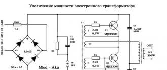
Here is a classic taschibra electronic transformer circuit. This is a simple push-pull half-bridge autogenerator inverter with a symmetrical dynistor-based start circuit. It is he who gives the initial impulse, as a result of which the circuit starts up. There are two high voltage reverse conduction transistors. In the native circuit there were mje13003, two half-bridge capacitors of 400 volts, oh, 1 Mkf, a feedback transformer with three windings, two of which are master or base windings. Each of them consists of 3 turns of 0.5 mm wire. The third winding is current feedback.
At the input there is a small 1 ohm resistor as a fuse and a diode rectifier. The electronic transformer, despite a simple circuit, works flawlessly. This option does not have protection against short circuits, therefore, if you short-circuit the output wires, there will be an explosion - this is at least.
There is no stabilization of the output voltage, since the circuit is designed to work with a passive load in the face of office halogen lamps. The main power transformer has two - primary and secondary. The latter is designed for an output voltage of 12 volts plus or minus a couple of volts.
The first tests showed that the transformer has quite a lot of potential. Then the author found on the Internet a patented scheme of a welding inverter built almost according to the same scheme and immediately created a board for a more powerful version. I made two boards, because in the beginning I wanted to build a resistance welding machine. Everything worked without any problems, but then I decided to rewind the secondary winding in order to film this video, since the initial winding gave out only 2 volts and a colossal current. And to make measurements of such currents at the moment is not possible due to the lack of the necessary measuring equipment.
There is a more powerful circuit in front of you. There are even fewer details. A couple of little things were taken from the first diagram. This is a feedback transformer, a capacitor and a resistor in the starting circuit, a dinistor.

Let's start with transistors. The motherboard had mje13003 in a to-220 package. Were replaced by more powerful mje13009 from the same line. the diodes on the board were of the type n4007 in one ampere. Replaced the assembly with a current of 4 amperes and with a reverse voltage of 600 volts. Any diode bridges of similar parameters will do. The reverse voltage must be at least 400 volts and the current must be at least 3 amperes. Film half-bridge capacitors with a voltage of 400 volts.


Electronic transformers are replacing bulky steel core transformers. The electronic transformer itself, unlike the classical one, is a whole device - a voltage converter.

Such converters are used in lighting to power 12 volt halogen lamps. If you have repaired chandeliers with a remote control, then you have probably met them.
Here is the circuit of the electronic transformer JINDEL(model GET-03) with short circuit protection.
![]()

The main power elements of the circuit are n-p-n transistors MJE13009, which are included according to the half-bridge scheme. They operate in antiphase at a frequency of 30 - 35 kHz. All the power supplied to the load is pumped through them - halogen lamps EL1 ... EL5. Diodes VD7 and VD8 are needed to protect transistors V1 and V2 from reverse voltage. A symmetrical dinistor (aka diac) is required to start the circuit.
On the transistor V3 ( 2N5551) and elements VD6, C9, R9 - R11 implemented a short-circuit protection circuit at the output ( short circuit protection).
If a short circuit occurs in the output circuit, then the increased current flowing through the resistor R8 will trigger the transistor V3. The transistor will open and block the operation of the DB3 dinistor, which starts the circuit.
Resistor R11 and electrolytic capacitor C9 prevent false operation of the protection when the lamps are turned on. At the moment the lamps are turned on, the filaments are cold, therefore, the converter produces a significant current at the beginning of the start.
To rectify the 220V mains voltage, a classic bridge circuit of 1.5-ampere diodes is used 1N5399.
The L2 inductor is used as a step-down transformer. It takes up almost half of the space on the converter PCB.
Due to its internal structure, the electronic transformer is not recommended to be switched on without load. Therefore, the minimum power of the connected load is 35 - 40 watts. The range of operating powers is usually indicated on the body of the product. For example, on the case of an electronic transformer, which in the first photo shows the output power range: 35 - 120 watts. Its minimum load power is 35 watts.
EL1 ... EL5 halogen lamps (load) are best connected to an electronic transformer with wires no longer than 3 meters. Since a significant current flows through the connecting wires, long wires increase the total resistance in the circuit. Therefore, lamps farther away will shine dimmer than those that are closer.
It is also worth considering that the resistance of long wires contributes to their heating due to the passage of significant current.
It is also worth noting that, due to their simplicity, electronic transformers are sources of high frequency interference in the network. Usually, a filter is placed at the input of such devices, which blocks interference. As you can see from the diagram, there are no such filters in electronic transformers for halogen lamps. But in computer power supplies, which are also assembled according to the half-bridge scheme and with a more complex master oscillator, such a filter is usually mounted.
Electronic transformer - network switching power supply, which is designed to power 12 Volt halogen lamps. Read more about this device in the article "". The device has a fairly simple circuit. A simple push-pull autogenerator, which is made according to a half-bridge circuit, the operating frequency is about 30 kHz, but this indicator strongly depends on the output load. The circuit of such a power supply is very unstable, does not have any protection against short-circuit at the output of the transformer, perhaps because of this, the circuit has not yet found widespread use in amateur radio circles. Although recently, in various forums, there has been a promotion of this topic. People offer various options for finalizing such transformers. Today I will try to combine all these improvements in one article and propose options not only for improvements, but also for powering the ET.
We will not go deep into the basis of the work of the scheme, but we will immediately get down to business. We will try to modify and increase the power of the Chinese ET Taschibra by 105 watts.
To begin with, I want to explain why I decided to take on the power-up and alteration of such transformers. The fact is that recently a neighbor asked to make him a custom-made charger for a car battery, which would be compact and lightweight. I didn't want to collect, but later I came across interesting articles in which the alteration of an electronic transformer was considered. This gave me an idea - why not try it?
Thus, several ETs from 50 to 150 watts were acquired, but experiments with rework did not always end successfully, of all, only 105 watts ET survived. The disadvantage of such a unit is that its transformer is not circular, and therefore it is inconvenient to rewind or wind the turns. But there was no other choice and it was this block that had to be redone.
As we know, these units do not turn on without load, this is not always an advantage. I plan to get a reliable device that can be freely used for any purpose, without fear that the power supply may burn out or fail in case of a short circuit.
Revision number 1
The essence of the idea is to add protection against short-circuit, also to eliminate the above drawback (activation of the circuit without an output load or with a low-power load).

Looking at the unit itself, we can see the simplest UPS circuit, I would say that the circuit is not fully worked out by the manufacturer. As we know, if you close the secondary winding of the transformer, then in less than a second the circuit will fail. The current in the circuit rises sharply, the keys fail in an instant, and sometimes the basic limiters. Thus, the repair of the circuit will cost more than the cost (the price of such an ET is about $ 2.5).

The feedback transformer consists of three separate windings. Two of these windings feed the basic key chains.
To begin with, we remove the communication winding on the OS transformer and put a jumper. This winding is connected in series with the primary winding of the pulse transformer. Then we wind only 2 turns on the power transformer and one turn on the ring (OS transformer). For winding, you can use a wire with a diameter of 0.4-0.8 mm.


Next, you need to select a resistor for the OS, in my case it is 6.2 ohms, but the resistor can be selected with a resistance of 3-12 ohms, the higher the resistance of this resistor, the lower the short circuit protection current. The resistor in my case is a wire-wound resistor, which I do not advise. We select the power of this resistor 3-5 watts (you can use from 1 to 10 watts).

During a short circuit on the output winding of the pulse transformer, the current in the secondary winding drops (in standard ET circuits, with a short circuit, the current increases, disabling the keys). This leads to a decrease in the current in the OS winding. Thus, the generation stops, the keys themselves are locked.
The only drawback of such a solution is that with a long-term short circuit at the output, the circuit breaks down, since the keys are heated and quite strong. Do not expose the output winding to a short circuit with a duration of more than 5-8 seconds.
The circuit will now start without load, in a word we received a full-fledged UPS with short circuit protection.

Revision number 2
Now we will try, to some extent, to smooth out the mains voltage from the rectifier. For this we will use chokes and a smoothing capacitor. In my case, a ready-made choke with two independent windings was used. This choke was removed from the DVD player UPS, although homemade chokes can be used.

After the bridge, an electrolyte with a capacity of 200 μF with a voltage of at least 400 volts should be connected. The capacitance of the capacitor is selected based on the power of the 1μF power supply per 1 watt of power. But as you remember, our power supply unit is designed for 105 watts, why is the capacitor used at 200μF? You will understand this very soon.
Revision number 3
Now about the main thing - powering up the electronic transformer and is it real? In fact, there is only one reliable way to power up without much rework.
For powering up, it is convenient to use an ET with a ring transformer, since it will be necessary to rewind the secondary winding, it is for this reason that we will replace our transformer.
The mains winding is stretched along the entire ring and contains 90 turns of wire 0.5-0.65 mm. The winding is wound on two folded ferrite rings, which were removed from an ET with a power of 150 watts. The secondary winding is wound based on the needs, in our case it is designed for 12 volts.
It is planned to increase the power up to 200 watts. That is why the electrolyte was needed with a margin, which was mentioned above.
We replace the half-bridge capacitors with 0.5 μF, in the standard circuit they have a capacity of 0.22 μF. Replace bipolar keys MJE13007 with MJE13009.
The power winding of the transformer contains 8 turns, the winding was made with 5 cores of 0.7mm wire, so we have a wire in the primary with a total cross section of 3.5mm.
Go ahead. Before and after the chokes, we put film capacitors with a capacity of 0.22-0.47 μF with a voltage of at least 400 Volts (I used exactly those capacitors that were on the ET board and which had to be replaced to increase the power).
Fluorescent and halogen lamps are gradually becoming a thing of the past, giving way to LED lamps. In the lamps where they were used, unnecessary electronic transformers were left, which were responsible for lighting these lamps. It seems that unnecessary - a place in the trash heap. But this is not the case. These transformers can be used to assemble powerful power supplies that can power power tools, LED strips, and more.
Electronic transformer device
The massive transformers familiar to us have recently begun to be replaced by electronic ones, which are distinguished by their low cost and compactness. The dimensions of the electronic transformer are so small that they are built into the housings of compact fluorescent lamps (CFLs).
All such transformers are made according to the same scheme, the differences between them are minimal. The circuit is based on a symmetrical oscillator, otherwise called a multivibrator.
They consist from a diode bridge, transistors and two transformers: matching and power... These are the main parts of the circuit, but not all. In addition to them, the circuit includes various resistors, capacitors and diodes.
Schematic diagram of an electronic transformer.
In this circuit, direct current from the diode bridge is fed to the transistors of the oscillator, which pump energy into the power transformer. The ratings and type of all radio components are selected so that a strictly defined voltage is obtained at the output.
If you turn on such a transformer without load, then the autogenerator will not start and there will be no voltage at the output.
DIY assembly
![]() Electronic ballast can be bought in a store or found in your bins, but the most interesting option would be to assemble an electronic transformer with your own hands. It is assembled quite simply, and most of the necessary parts can be dig into broken power supplies and in energy-saving lamps.
Electronic ballast can be bought in a store or found in your bins, but the most interesting option would be to assemble an electronic transformer with your own hands. It is assembled quite simply, and most of the necessary parts can be dig into broken power supplies and in energy-saving lamps.
- Required components: A diode bridge with a reverse voltage of at least 400 V and a current of at least 3 A or four diodes with the same characteristics.
- 5 amp fuse.
- Symmetrical dynistor DB3.
- 500 kOhm resistor.
- 2 resistors 2.2 Ohm, 0.5 W.
- 2 bipolar transistors MJE13009.
- 3 film capacitors 600 V, 100 nF.
- 2 toroidal cores.
- Lacquered wire 0.5 mm².
- Conventional insulated wire 2.5 mm².
- Radiator for transistors.
- Bread board.
It all starts with a breadboard, on which you will install all the radio components. On the market, you can buy two types of boards - with one-sided metallization on brown fiberglass.
And with double-sided end-to-end, on green.
The choice of the board depends on how much time and effort you will spend on assembling the project.
Brown boards are of disgusting quality. They are metallized in such a thin layer that gaps are visible in some places... It is poorly wetted with solder, even if you use a good flux. And everything that was soldered - comes off along with the metallization at the slightest effort.
Green ones cost one and a half to two times more, but everything is in order with the quality. Metallization on them with thickness has no problems. All holes in the board are tinned at the factory, due to which copper does not oxidize and problems do not arise during soldering.
You can find and buy these layouts both in the nearest radio store and on aliexpress. In China, they cost half the price, but delivery will have to wait.
Choose radio components with long leads, they will come in handy when installing the circuit. If you are going to use used parts, be sure to check their functionality and the absence of external damage.
The only part you have to make yourself is the transformer.
The matching wire must be wound with a thin wire. Number of turns in each winding:
- I - 7 turns.
- II - 7.
- III - 3.
Do not forget to fix the windings with tape, otherwise they will creep.
The power transformer consists of only two windings. Wrap the primary with a 0.5mm² wire, and the secondary - 2.5mm². The primary and secondary housing consist of 90 and 12 turns, respectively.
For soldering, it is better not to use "old-fashioned" soldering irons - they can easily burn temperature-sensitive radioelements. Take a better soldering iron with power adjustment, they do not overheat, unlike the first ones.
install the transistors on the radiators in advance. Doing this on an already assembled board is extremely inconvenient. You need to assemble the scheme from small parts to large ones. If you install the large ones first, they will get in the way when soldering the small ones. Consider this.
When assembling, look at the schematic diagram, all connections of radioelements must correspond to it. Slide the leads of the parts into the holes on the board and bend them in the desired direction. If the length is not enough, extend them with a wire. After soldering, glue the transformers to the board with epoxy resin.
After assembly, connect a load to the terminals of the device and make sure that it works.
Conversion into a power supply
![]() It so happens that the batteries of the power tool fail, but there is no opportunity to buy a new one. In this case, an adapter in the form of a power supply will help. After a little modification, such an adapter can be assembled from an electronic transformer.
It so happens that the batteries of the power tool fail, but there is no opportunity to buy a new one. In this case, an adapter in the form of a power supply will help. After a little modification, such an adapter can be assembled from an electronic transformer.
Details that will be needed for the rework:
- NTC thermistor 4 ohm.
- Capacitor 100 μF, 400 V.
- Capacitor 100 uF, 63V.
- Film capacitor 100 nF.
- 2 resistors 6.8 Ohm, 5 W.
- 500 ohm resistor, 2 W.
- 4 diodes KD213B.
- Radiator for diodes.
- Toroidal core.
- Wire with a cross section of 1.2 mm².
- A piece of a circuit board.
Before starting work, check if you have forgotten any part. If all parts are in place, start converting the electronic transformer into a power supply.
Solder a 400 V, 100 μF capacitor to the diode bridge output. To reduce the charging current of the capacitor, solder the thermistor into the break in the power wire. If you forget to do this, the diode bridge will burn out the first time you turn on the network.
Disconnect the second winding of the matching transformer and replace it with a jumper. Add one winding to both transformers. Make one turn on the matching one, and two on the power one. Connect the windings to each other by soldering two parallel-connected 6.8 Ohm resistors into the wire break.
To make a choke, wind 24 turns of 1.2 mm² wire around the core and secure it with tape. Then, on the breadboard, assemble the remaining radio components according to the diagram and connect the assembly to the main circuit. Remember to install diodes on the heatsink, when working under load, they get very hot.
Secure the entire structure in any suitable enclosure and the power supply can be considered assembled.
After final assembly, plug in the device and test its operation. It should give out a voltage of 12 volts. If the power supply gives them out, you did your job perfectly well. If it doesn't work, check if you took a non-working transformer.
Recently in a store I came across an electronic transformer for halogen lamps. Such a transformer costs a penny - only $ 2.5, which is several times cheaper than the cost of the components used in it. The block was purchased for experiments. As it turned out later, it did not have protection and a real explosion occurred during a short circuit ... The transformer was quite powerful (150 watts), so a fuse was installed at the entrance, which literally burst. After checking, it turned out that half of the components had burned out. Repair will be expensive, and there is no need to waste time and nerves, it is better to buy a new one. The next day, three transformers were bought at once for 50, 105 and 150 watts.
It was planned to modify the unit, since it was a UPS - without any filters and protections.

After revision, a powerful UPS should have been obtained, the main feature of which is compactness.
To begin with, the unit was equipped with a surge protector.

The choke was removed from the DVD player's power supply, it consists of two identical windings, each containing 35 turns of 0.3mm wire. Only after passing through the filter, voltage is applied to the main circuit. To smooth out low-frequency interference, capacitors of 0.1 μF were used (select with a voltage of 250-400 volts). The LED indicates the presence of mains voltage.
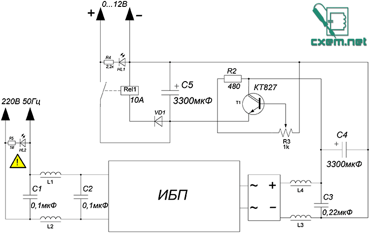

Voltage regulator
A circuit using only one transistor was used. This is the simplest circuit there is, contains a couple of components and works very well. The disadvantage of the circuit is the overheating of the transistor under heavy loads, but it's not so bad. In the circuit, you can use any powerful bipolar LF reverse conduction transistors - KT803,805,819,825,827 - I recommend using the last three. The trimmer can be taken with a resistance of 1 ... 6.8k, we take an additional protective resistor with a power of 0.5-1 Watt.
The regulator is ready, let's move on.

Protection
Another simple scheme, in fact, is protection against overdriving. The relay is literally any 10-15 Ampere. Any rectifier diode can also be used, with a current of 1 ampere or more (the widely used 1N4007 does an excellent job). The LED signals the wrong polarity. This system cuts off the voltage if the device under test is connected to the short circuit or incorrectly connected. The power supply unit can be used to test the performance of home-made ULFs, converters, car radios, etc., while you do not need to be afraid that you will suddenly confuse the polarity of the power supply.

In the future, we will look at a few more simple alterations of the electronic transformer, but for now we have a simple, compact and powerful UPS that can be used as a laboratory unit for a beginner.
List of radioelements
| Designation | A type | Denomination | Quantity | Note | Shop | My notebook |
|---|---|---|---|---|---|---|
| T1 | Bipolar transistor | KT827A | 1 | Into notepad | ||
| VD1 | Rectifier diode | 1N4007 | 1 | Into notepad | ||
| Diode bridge | 1 | Into notepad | ||||
| C1, C2 | Capacitor | 0.1 uF | 2 | Into notepad | ||
| C3 | Capacitor | 0.22 μF | 1 | Into notepad | ||
| C4-C5 | Electrolytic capacitor | 3300 uF | 2 | Into notepad | ||
| R2 | Resistor | 480 Ohm | 1 | Into notepad | ||
| R3 | Variable resistor | 1 kΩ | 1 | Into notepad | ||
| R4 | Resistor | 2.2 k Ohm | 1 | Into notepad | ||
| R5 | Resistor |