Those who like to do everything with their own hands are offered a simple tester based on the M2027-M1 microammeter, which has a measurement range of 0-300 μA, an internal resistance of 3000 Ohm, an accuracy class of 1.0.
Required details
This is a tester that has a magnetoelectric mechanism for measuring current, so it only measures direct current. A moving coil with an arrow is attached to the guy wires. It is used in analog electrical measuring instruments.
Finding radio parts at a flea market or buying radio parts at a store will not be a problem. There you can also purchase other materials and components, as well as attachments to the multimeter. In addition to a microammeter, you will need:
If a person decides to make himself a multimeter with his own hands, it means that he has no other measuring instruments. Based on this, we will continue to act.
Selection of measuring ranges and calculation of resistor values
Let's define the range of measured voltages for the tester. Let's choose the three most common, covering most of the needs of the radio amateur and home electrician. These ranges are 0 to 3 V, 0 to 30 V, and 0 to 300 V.
The maximum current passing through a homemade multimeter is 300 μA. Therefore, the task is reduced to the selection of additional resistance, at which the arrow deviates to full scale, and a voltage corresponding to the limit value of the range will be applied to the serial chain Rd + Rvn.
That is, on the 3 V range, Rtot = Rd + Rvn = U / I = 3 / 0.0003 = 10000 Ohm,
where Rtot is the total resistance, Rd is the additional resistance, and Rvn is the internal resistance of the tester.
Rd = Rtot-Rvn = 10000-3000 = 7000 Ohm or 7kOhm.
On the 30V range, the total resistance should be 30 / 0.0003 = 100000 ohms
Rd = 100000-3000 = 97000 Ohm or 97 kOhm.
For 300 V range, Rtotal = 300 / 0.0003 = 1,000,000 Ohm or 1 mOhm.
Rd = 1000000-3000 = 997000 Ohm or 997 kOhm.
 To measure currents, select the ranges from 0 to 300 mA, from 0 to 30 mA and from 0 to 3 mA. In this mode, the shunt resistance Rsh is connected to the microammeter in parallel. therefore
Rtot = Rsh * Rin / (Rsh + Rin).
And the voltage drop across the shunt is equal to the voltage drop across the tester coil and is equal to Upr = Ush = 0.0003 * 3000 = 0.9 V.
Hence, in the range of 0 ... 3 mA
Rtot = U / I = 0.9 / 0.003 = 300 Ohm.
Then
Rsh = Rtot * Rvn / (Rvn-Rtot) = 300 * 3000 / (3000-300) = 333 Ohm.
In the range 0 ... 30 mA Rtot = U / I = 0.9 / 0.030 = 30 Ohm.
Then
Rsh = Rtot * Rvn / (Rvn-Rtot) = 30 * 3000 / (3000-30) = 30.3 Ohm.
Hence, in the range of 0 ... 300 mA Rtotal = U / I = 0.9 / 0.300 = 3 Ohm.
Then
Rsh = Rtot * Rvn / (Rvn-Rtot) = 3 * 3000 / (3000-3) = 3.003 Ohm.
Fitting and installation
To make the tester accurate, you need to adjust the resistor values. This part of the work is the most painstaking. We will prepare a board for installation. To do this, you need to draw it into squares measuring a centimeter by centimeter or slightly less.
Then, with a boot knife or something similar, the copper coating is cut along the lines to the fiberglass base. The result is isolated contact pads. We marked where the elements will be located, it turned out a semblance of a wiring diagram right on the board. In the future, the tester elements will be soldered to them.

In order for a homemade tester to give correct readings with a given error, all its components must have at least the same accuracy characteristics and even better.
The internal resistance of the coil in the magnetoelectric mechanism of the microammeter will be considered equal to the 3000 Ohm declared in the passport. The number of turns in the coil, the diameter of the wire, the electrical conductivity of the metal from which the wire is made are known. This means that the manufacturer's data can be trusted.
But the voltages of 1.5 V batteries may differ slightly from those declared by the manufacturer, and knowledge of the exact voltage value will then be required to measure the resistance of resistors, cables and other loads with a tester.
Determining the exact voltage of the battery
In order to find out the actual voltage of the battery yourself, you will need at least one accurate resistor with a nominal value of 2 or 2.2 kOhm with an error of 0.5%. This resistor value was chosen due to the fact that when a microammeter is connected in series with it, the total resistance of the circuit will be 5000 ohms. Therefore, the current going through the tester will be about 300 μA and the needle will deflect to full scale.
I = U / R = 1.5 / (3000 + 2000) = 0.0003 A.
If the tester shows, for example, 290 μA, then the battery voltage is
U = I * R = 0.00029 (3000 + 2000) = 1.45 V.
Now, knowing the exact voltage on the batteries, having one exact resistance and a microammeter, you can select the required resistance values for shunts and additional resistors.
Collecting the power supply
The power supply for the multimeter is assembled from two series-connected batteries of 1.5 V. After that, a microammeter and a 7 kOhm resistor pre-selected at the nominal value are connected to it in series.
The tester should show a value close to the current limit. If the device goes off scale, then a second, small value must be connected in series to the first resistor.
If the readings are less than 300 μA, then a large resistance is connected in parallel to these two resistors. This will reduce the total resistance of the pull-up resistor.
This operation continues until the needle is at the 300 µA full scale, which signals a fine fit.

To select an accurate 97 kOhm resistor, select the closest one that is suitable for the nominal value, and do the same procedures as with the first 7 kOhm. But since a 30 V power supply is required here, it will be necessary to rework the multimeter's power supply from 1.5 V batteries.
A block with an output voltage of 15-30 V is assembled, as long as it is enough. For example, it turned out 15 V, then the entire adjustment is made on the basis that the arrow should tend to a reading of 150 μA, that is, to half of the scale.
This is permissible, since the tester's scale is linear when measuring current and voltage, but it is desirable to work with full voltage.
DC current or voltage generators are required to adjust the 997 kΩ pull-up resistor for the 300 V range. They can also be used as attachments to a multimeter when measuring resistance.
Resistor ratings: R1 = 3 Ohm, R2 = 30.3 Ohm, R3 = 333 Ohm, R4 variable by 4.7 kOhm, R5 = 7 kOhm, R6 = 97 kOhm, R7 = 997 kOhm. Are matched by fit. Power supply 3 V. Installation can be done by hanging elements directly on the board.
The connector can be installed on the side of the box into which the microammeter is cut. The probes are made of single-core copper wire, and the cords for them are made of stranded wire.
The shunts are connected with a jumper. As a result, a tester is obtained from a microammeter, which can measure all three main parameters of electric current.
In this article, I will tell you how to make a tester from a smartphone for continuity of electrical circuits for an open or short circuit. In fact, I will make a cell phone attachment (or rather an adapter with probes), with which you can take measurements. Its circuit is incredibly simple and contains one resistor.
Such a craft can be useful to you if your working multimeter breaks down. Or you don't want to take it with you. Personally, I made such an adapter-attachment and threw it into the glove compartment of the car. Now, when I need to ring a light bulb, a fuse or something else, I take out the probes and connect them to the phone.
What are the possibilities of a tester from a smartphone?
With this tester, you can:- - Ring the circuit for an open or short circuit.
- - Find out the approximate resistance value (0-70 Ohm).
- - Smartphone beeps when continuity is detected.
Adapter-attachment diagram
Headset connector pinout.
We will feed the signal from the probes to the microphone input.

Everything can be done by surface mounting by soldering the resistor to the plug, soldering the wires and filling the whole thing with hot glue. Or make a separate node with a bifurcation for the probes, put on heat shrinkage and blow it off. As a last resort, use electrical tape. 15 minutes of work, no more ...

Smartphone app
After the adapter is soldered, download the application to (active link to the application) and install.We launch the application and connect the adapter. Everything should work. If you close the probes, then you will hear a beep, then everything is fine and you can use it.
Initially, zeros are shown:

And when you close the probes between each other, such a word appears and the phone beeps.

Caution when using the tester
This tester cannot measure circuits where there is voltage! Since your smartphone may fail. Also, keep in mind that in some circuits there may be a residual voltage on the capacitors of the device, which will also be dangerous for a smartphone.The thing is sometimes very necessary and fit in the household.
Smartphones have long been included in our lives and are finding more and more use.
Having made myself a mini-tester, I have been using it for several years now in the repair of household electrical and radio equipment. Assembled according to the classical scheme, the device allows measuring voltages up to 300 V in AC and DC circuits with sufficient accuracy for practice, checking resistors, diodes, transistors and capacitors.
To manufacture such a mini-tester, a small number of radio components are required, and none of them are expensive and scarce. They are always, as they say, at hand, they can be easily found in stock at any radio amateur. And as a supporting structure, a circuit board and a body of the device ... the measuring head itself M42100 (or a similar type) is used, designed to measure a DC voltage of 3 or 30 V.

Miniature sockets are mounted on the head body. There are also "seats" for the screw MZ (the probe "General" is attached to it), the variable resistor R2 "Ust.O" and the lamp FRM-1, which acts as a case for a power supply such as STs32, STs21, etc. If desired, you can add a phase indicator to the device (shown in dotted lines in the diagram) - there is enough space inside the head.
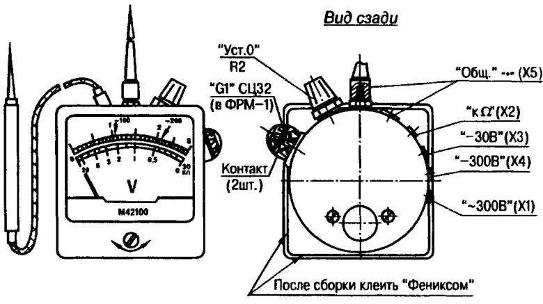
The scale "-30 V" is basic, it is taken ready-made. It is used to bind the divisions in the range with the upper limit "-300 V". And for measuring alternating voltages (due to the nonlinearity of the initial section), as well as for measuring resistances, it is desirable to have additional scales. They are graded according to methods that are described in sufficient detail in the popular literature.
It is advisable to replace the glass in the tester with a plexiglass plate - it will not break when the device is hit or dropped.
V.REZKOV, Vitebsk, Belarus
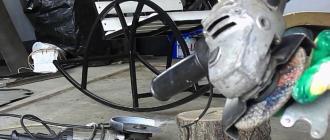
Despite the high reliability of modern car electrics, you still have to deal with its repair. Most often, lights, headlights, side lights or direction indicators stop working. The cause of the malfunction can be both the light bulb itself and the current-carrying contacts or a fuse. All three faults may occur at once. Due to poor contact in the socket or lamp block, it may burn out. At the moment of burnout, an arc arises in the bulb itself, shortening the filament, which leads to a sharp increase in the current circuit. When a light bulb burns out, the fuse often blows too.
It is not an easy task to understand the cause of a breakdown without instruments. We'll have to substitute knowingly serviceable parts. The malfunction can be determined using an arrow tester or multimeter, but not everyone has such a device and it is not very convenient to work with it in a car, especially in bad weather. It is much more convenient to look for a malfunction with the simplest universal do-it-yourself automotive tester.
You can make an automotive tester probe from any ballpoint pen by removing the stylus and placing just one LED of any type and a current limiting resistor in its housing. The parts are connected to each other according to the below given electrical schematic diagram. As you can see, there is no simpler scheme. Any car enthusiast who has no experience in the manufacture of electronic devices can make such a probe with his own hands.

For reliable electrical contact when touching the probe and the possibility of puncturing the insulation of wires when searching for faults, the end of the probe is made in the form of a steel tip. To make such an end from the writing rod, you need to remove the writing unit and insert a thin sewing needle into it from the side of the paste intake. The needle will squeeze out the ball and the sharp end will come out of the nib. If it is inserted with considerable force, then it will be firmly fixed. A conductor is soldered to the needle itself, going to the LED.

The nib should be taken with a brass nib and a large ball (pens with such nibs leave a wide line), otherwise the needle may not enter the nib and will not protrude enough by 1.5-2 mm.
The conductor for connecting the car tester to the minus of the battery or the car body can be soldered directly to the terminal of the resistor R1. But in order to be able to change the conductor in case of its breakage or if a longer wire is required, I made its connection on the thread.

To do this, it is enough to melt a section of a tube with an internal thread, heating it with a soldering iron into a prepared hole in the body of the pen, having previously soldered a conductor of the required length to it.

The LED is installed on the side of the car tester's case, but you can install it on the end of the case, and bring the negative wire to the side.
How to use the tester
I will give examples of how you can check the health of a battery, a fuse, an incandescent light bulb and an electromagnetic relay with a tester.
How to check the battery
To check the presence of voltage at the battery terminals, you need to connect the crocodile clip to the negative terminal of the battery, and touch the positive terminal with the end of the tester probe.

How to check a fuse
How to check an incandescent light bulb
To check the incandescent light bulb with the tester, you need to touch the positive terminal of the battery with one terminal of the lamp base, and touch the tester's probe to the second terminal of the light bulb.

If the LED lights up, then the light is working. If the bulb contains two filaments, such as a car headlight bulb, the filaments are checked one at a time.
How to test a car relay
The automotive relay, in addition to the electromagnet winding, also has contacts that burn out over time and can stop switching electrical circuits. Using a tester, you can check both the integrity of the winding and the serviceability of the contacts.

A standard automotive relay has the following wiring diagram. Conclusions 85 and 86 are made from the relay coil. The output at number 30 is made from the movable contact, 87a from the normally closed contact with the movable contact 30 and 87, this is the output from the contact to which the movable contact 30 is connected when the supply voltage is applied to the winding.

To check the relay winding, you need to touch one of its terminals 85 or 86 to the positive terminal of the battery, and touch the second terminal with the tester probe. If the LED is on, then the winding is intact. The serviceability of the contacts is checked by touching the output of the movable contact 30 to the battery terminal, and the probe to terminal 87a. In the same way, it is easy to check any switches and microswitches.
How to use the tester
when repairing a car's electrical wiring
In practice, when troubleshooting a car's electrical system, there is no need to remove fuses and bulbs. As you know, the negative terminal of the battery is connected to the car body and all electrical equipment in the car is also connected to the body with one terminal. Thus, it was possible to halve the number of wiring wires and increase its reliability. The only exceptions are activators for car door locks, since they need to be supplied with voltage of different polarity, depending on the need to open or close the door lock.
For example, if the bulb of one of the headlights does not shine. A malfunction can be in one of the elements supplying voltage to the light bulb - a switch in the cabin, a relay, a fuse, or a malfunction of the light bulb itself. Most likely, the light bulb itself has burned out, and it is necessary to start checking with it.
To do this, you need to hook the crocodile tester clip on any bare metal part of the car body or the negative terminal of the battery. Check the quality of the contact by touching the positive side of the battery with the stylus. The LED should be on. Turn on the inoperative headlight and with the end of the probe, in turn, touch all the contacts of the light bulb. If this is not possible, then you can pierce each wire with a probe needle in turn, and if there is no voltage on either one (the probe LED did not light up), then the light bulb is intact, and you need to check the fuse.
According to the diagram, see where it is installed and check it without even removing it from the block. To do this, it is enough to touch first to one of its conclusions, and then to another. The tester's LED should light up every time. If it shines only when you touch one of the terminals, then the fuse is blown. If you cannot get to the fuse terminals, then you need to remove it and check it, as described in the article above.
Using this technique, any electrical wiring wires and contacts in the car are checked.
In this short review, we will consider the possibility of self-manufacturing of such an interesting and useful home appliance in everyday life as a simple tester. Such a simple device is very useful for promptly checking the performance of radio components and for use in everyday life.
Despite the fact that you can buy a tester in stores at a fairly low price, self-assembly of such a small device will be an excellent practice for any novice amateur radio technician.

The assembled device is very convenient and may well be used even by masters of their craft. You can see a photo of a homemade tester in the review below.


Schematic diagram of a simple tester
Such a device includes the minimum number of elements for assembly, which are in use in almost any home or can easily be purchased, if necessary, at any radio parts store or even in a hardware store.

In essence, this is the only multivibrator that is assembled on a transistor basis. With its help, rectangular-type pulses are generated.


The control circuit of the current is connected to the elements of the multivibrator on a serial basis in opposite and parallel using two color LEDs.

As a result, the circuit to be tested with the device is tested with AC current, which ensures high accuracy of the test.

How the tester works
An alternating current is removed from the main working component, which is a multivibrator, which in amplitude is approximately equal to that supplied by the power source. Anything above 3.7 V, for example, 16 or 25 V, is suitable as a condensing element.


Naturally, with an open circuit, the LEDs do not light up. When the circuit is closed and current flows through the circuit, the LEDs light up. It's simple.

With such a device, you can very quickly and efficiently check any element for operability or a circuit for a break in it. It is very convenient for use at home, especially by a not particularly well trained person. DIY transistor tester - what could be simpler?


Such a device is assembled either using a simple printed circuit board or by means of a hinged mount. Also in the field of application includes the ability to determine the "plus" and "minus" when you do not know where they are in the element under study. For battery use, 2-3 AAA batteries can be used to minimize the size of the device.

The second method of making a compact tester for use in a car. Such a device will have literally 2 main working functions - the ability to read the voltage “on the ground” and the presence of 12 V in the circuit. Moreover, all this will be available literally when one wiring is connected to the machine's network.


What is needed to create such a functional device:
- an ordinary medical syringe for 5 cm3;
- batteries LR-44 in the amount of 4 pieces;
- two small LED elements with a resistor component;
- a small piece of steel wire;
- wiring with a clamp at its end.

Automotive homemade testers circuits
- In the opposite way, we solder both LEDs used in parallel;
- Through the resistor used, one of the ends must be soldered tightly to the steel wire;
- Install batteries one by one directly inside the syringe body. These are chosen because they fit perfectly into a five-cube syringe;
- The probe is isolated from the syringe with a plastic tube, you check the functionality directly in the machine in practice;
- Check if the LEDs on the 12V element light up.

So, the use of the tester made by you yourself is more than conditioned in everyday life. Believe me, such a small device will definitely come in handy, if not in everyday life, then at those moments when you need to check something in your home or car's electrical network.

Making a tester with your own hands can seriously raise the self-esteem of any person who does not believe that he can do anything with his own hands - only desire is important.

Photos of testers with their own hands