Virtually all headsets that are designed to work with a PC have such "pathetic" characteristics that you try to use a microphone from such a headset for sound recording or the same karaoke, nothing but disappointment will not get. The reason here is one - all such microphones are designed for voice transmission and have a very narrow frequency range. This not only reduces the price of the design itself, but also promotes intelligibility of speech, which is the main requirement of the headset.
Attempts to connect a conventional dynamic or electret microphone usually end in failure - the level from such a microphone is clearly not enough to "build up" the sound card. Additionally, ignorance of the input circuitry of sound cards and improper connection A dynamic microphone breaks the case. Collect the microphone amplifier and plug it "in the mind"? It would be nice, but it's much easier to use the IEC-3 microphone, which at one time was widely used in portable equipment and is still quite common. But to connect "on the mind", of course, have to.
This microphone is electret, has high enough characteristics (the frequency range, for example, lies in the range of 50-15000 Hz) and, most importantly, it has a built-in source repeater assembled on a field effect transistor that not only matches the high resistance of the microphone to the amplifier, but also has more than enough output level for any sound card. The only, perhaps, lack - the microphone requires power. But the current consumption is so small that two finger batteries, connected in series, will last for many months of continuous operation. Let's take a look at the internal microphone circuit, which is located in an aluminum cup, and think about how to connect it to a computer:

Gray color indicates an aluminum cup, which is a screen and is connected to the common circuit wire. As I said, this microphone requires external power supply, and minus 3-5 V need to apply to the resistor (red wire), and plus - to blue. With white we will shoot a useful signal.
And now let's take a look at the microphone input circuit of the computer:
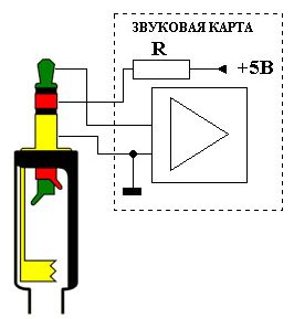
It turns the signal should be applied only to the tip of the connector, marked green, and the red sound card itself supplies +5 V through the resistor. This is done for powering the preamplifier headsets, if they are used. We will not use this voltage for two reasons: firstly, we need a different polarity, and if we simply "turn" the wires, the microphone will "strongly foil". Secondly, the PC power supply is impulse and the interference on these five volts will be decent. The use of galvanic cells in terms of interference is ideal - a clean "constant" without the slightest ripple. So, the full scheme of connecting our microphone to the computer will look like this:

The decoupling capacitor, whose rating can lie in the range 0.1 ... 1 μF, is ceramic.
Microphones (electrodynamic, electromagnetic, electret, coal) - basic parameters, marking and inclusion in electronic circuits.
In electronics, the microphone is widely used - a device that converts sound vibrations into electrical vibrations. A microphone is usually understood as an electrical device used to detect and amplify weak sounds.
Basic parameters of microphones
The quality of the microphone is characterized by several standard technical parameters: sensitivity, nominal frequency range, frequency response, directionality, dynamic range, the module of the total electrical resistance, the rated load resistance,
Marking
The microphone mark is usually applied on its body and consists of letters and numbers. Letters indicate the type of microphone:
MD ............... reel (or "dynamic"),
MDM ............ dynamic small-sized,
MM ............. miniature electrodynamic,
ML ............... tape,
MK ............... condenser,
MCE ............ electret,
MPE ............ piezoelectric.
The numbers indicate the serial number of the development. After the numbers are the letters A, T and B, indicating that the microphone is made in the export version - A, T - tropical, and B - is intended for household radio electronic equipment (REA). Marking the microphone MM-5 reflects its design features and consists of six characters:
first and second ............... MM - microphone is miniature;
the third ................................. 5 - the fifth design;
the fourth and fifth ........... two figures denoting the size;
sixth ............................... letter that characterizes the shape of the acoustic input (O - round hole, C - branch pipe, B - combined).
In the practice of radio amateurs, several basic types of microphones are used: coal, electrodynamic, electromagnetic, capacitor, electret and piezoelectric.
Electrodynamic microphones
(the name of microphones of this type is considered obsolete and now these microphones are called reel)
Microphones of this type are very often used by recording fans, due to their relatively high sensitivity and practical insensitivity to atmospheric influences, in particular, to the effect of wind. They are also not afraid of jolts, are easy to use and have the ability to withstand without damage large levels of signals. The positive qualities of these microphones prevail over their lack: the average quality of sound recording.
At present, for home radio amateurs, small-sized dynamic microphones produced by domestic industry are of great interest, which are used for sound recording, sound transmission, sound reinforcement and various communication systems. Microphones of four complexity groups are produced - 0, 1, 2 and 3. Microphones of small complexity groups 0, 1 and 2 are used for audio transmission, sound recording and amplification of music and speech, and for group 3 - for sound transmission, sound recording and speech amplification.
The symbol for the microphone consists of three letters and numbers. For example, MDM-1, a dynamic compact microphone of the first design.
Of special interest are electro-dynamic miniature microphones of the MM-5 series, which can be soldered directly to the amplifier board or used as an embedded element of electronic equipment. Microphones belong to the fourth generation of components, which are designed for CEA on transistors and integrated circuits. The MM-5 microphone is of the same type in two versions: high-impedance (600 Ohm) and low-impedance (300 Ohm), and thirty-eight standard sizes that differ only in the resistance of the DC winding, the location of the acoustic input and its type. Basic electroacoustic parameters and technical characteristics of microphones of the MM-5 series are given in Table. 3.2.
Table 3.2.
|
Microphone Type |
||
|
Execution option |
low-resistance |
high-resistance |
|
The module of the total electrical resistance of the winding, Ohm |
||
|
Sensitivity at a frequency of 1000 Hz, μV / Pa, not less than (load resistance) |
||
|
Average sensitivity in the range 500 ... 5000 Hz, μV / Pa, not less than (load resistance) |
1200 (3000 Ω) |
|
|
sensitivity in the nominal frequency range, dB, not more than |
||
|
Weight, g, not more than |
||
|
Service life, year, not less than |
||
|
Dimensions, mm |
||
Fig. 3.6. Schematic diagram of the switching on the input of the ultrasonic loudspeaker of the loudspeaker as a microphone
In the absence of a dynamic microphone, radio amateurs often use an ordinary electrodynamic loudspeaker instead (Figure 3.6).
Electromagnetic microphones
For low-frequency amplifiers assembled on transistors and having a low input impedance, electromagnetic microphones are usually used. Electromagnetic microphones are characterized by reversibility, that is, they can be used as telephones. A so-called differential microphone of the type DEMSH-1 and its modification DEMSH-1A are widely used. Good results are obtained when using instead of electromagnetic microphones DEMSh-1 and DEM-4M conventional electromagnetic headphones from the headphones TON-1, TON-2, TA-56, etc. (Fig. 3.7 ... 3.9).
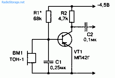
Fig. 3.7. Schematic diagram of switching on at the input of ultrasonic electromagnetic earphone as a microphone
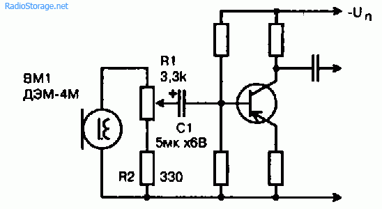
Fig. 3.8. Schematic diagram of the inclusion of an electromagnetic microphone at the input of ultrasonic transistors

Fig. 3.9. Schematic diagram of the inclusion of an electromagnetic microphone at the input of a high-frequency amplifier on an operational amplifier.
Electret microphones
Recently, electret condenser microphones have been used in household tape recorders. Electret microphones have the widest frequency range: 30 ... 20000 Hz. Microphones of this type give an electrical signal twice as large as conventional carbon.
The industry produces electret microphones MKE-82 and MKE-01 in size similar to coal MK-59 and the like, which can be installed in ordinary telephone tubes instead of coal ones without any alteration of the telephone set. This type of microphone is much cheaper than conventional condenser microphones, and therefore more affordable to radio amateurs. Domestic industry produces a wide range of electret microphones, among them the MKE-2 one-sided direction for 1-class coil tape recorders and for integration into the electronic equipment - MKE-3, MKE-332 and MKE-333. For radio amateurs, the most interesting is the condenser electret microphone MKE-3, which has a micro-miniature design. The microphone is used as an embedded device in domestic tape recorders, magnetoradio and radio tape recorders, such as Sigma-VEF-260, Tom-303, Romantik-306, etc.
The MKE-3 microphone is manufactured in a plastic case with a flange for mounting on the front panel of the radio device from the inside. The microphone is not directional and has a circle diagram. The microphone does not allow impacts and strong shaking. In Table. 3.3 the main technical specifications some brands of miniature condenser electret microphones. In Fig. 3.10 is a diagram of the inclusion of an electret microphone of the MKE-3 type distributed in radio amateur designs.
Table 3.3.
|
Microphone Type |
||||
|
Nominal operating frequency range, Hz |
||||
|
Free field sensitivity frequency of 1000 Hz, μV / Pa |
not more than 3 |
not less than 3 |
not less than 3 |
|
|
Uneven frequency response sensitivity in the range of 50 ... 16000 Hz, dB, not less than |
||||
|
The module of the total electrical resistance at 1000 Hz, Ohm, not more than |
||||
|
The equivalent sound pressure level, due to the microphone's own noises, dB, not more than |
||||
|
The average difference in sensitivity levels "Front-rear", dB |
not less than 12 |
not more than 3 |
||
|
Operating conditions: temperature, ° С relative air humidity, not more than |
95 ± 3% at 25 "C |
95 ± 3% at 25 "C |
93% at 25 "C |
|
|
Supply voltages, V |
||||
|
Overall dimensions (diameter x length), mm |
![]()
Fig. 3.10. Schematic diagram of the inclusion of a microphone type MKE-3 at the input of a transistor ultrasonic
Carbon microphones
Despite the fact that carbon microphones are gradually replaced by other types of microphones, but due to the simplicity of the design and high enough sensitivity, they still find their place in various communication devices. The most widespread are carbon microphones, so-called telephone capsules, in particular, MK-U, MK-16, MK-59, etc. The simplest scheme for incorporating a carbon microphone is shown in Fig. Z.P. In this scheme, the transformer should be boosting and for a carbon microphone with a resistance R = 300 ... 400 Ohm it can be wound on an S-shaped iron core with a cross section of 1 ... 1.5 cm2. The primary winding (I) contains 200 turns of PEV-1 wire 0.2 mm in diameter, and the secondary winding (II) consists of 400 turns of PEV-1 with a diameter of 0.08 ... 0.1 mm. Depending on their dynamic resistance, carbon microphones are divided into 3 groups:
1 ......... low-ohmic (about 50 Ohm) with a supply current of up to 80 mA;
2 ......... medium-resistive (70 ... 150 Ohm) with a supply current of not more than 50 mA;
3 ......... high-resistance (150 ... 300 Ohm) with a power supply current of not more than 25 mA.
It follows that in the circuit of a carbon microphone, it is necessary to set a current corresponding to the type of microphone. Otherwise, if the current is high, the coal powder will begin to cake and the microphone will deteriorate. In this case, nonlinear distortions appear. At a very low current, the sensitivity of the microphone decreases sharply. Coal capsules can work and with a reduced current of the power source, in particular, in amplifiers on lamps and transistors. The decrease in sensitivity with a reduced power supply of the microphone is compensated by simply increasing the amplification factor of the audio frequency amplifier. In this case, the frequency response improves, the noise level is significantly reduced, stability and reliability of operation are increased.

Fig. 3.11. Schematic diagram of the inclusion of a carbon microphone using a transformer
The option of incorporating a carbon microphone into the amplifier stage on a transistor is given in Fig. 3.12. The option of incorporating a carbon microphone in combination with a transistor at the input of a tube amplifier of the audio frequency as shown in Fig. 3.13 allows obtaining a large voltage gain.
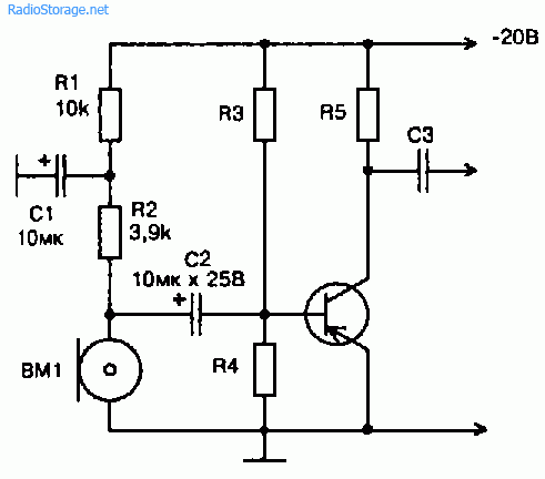
Fig. 3.12. Schematic diagram of the inclusion of a carbon microphone at the input of a transistor ultrasonic

Fig. 3.13. Schematic diagram of the inclusion of a carbon microphone at the input of a hybrid ultrasonic amplifier assembled on a transistor and an electron tube
Literature: V.M. Pestrikov. Encyclopedia of radio amateurs.
3.8. MICROPHONES
Microphones are classified on the basis of the conversion of acoustic vibrations into electrical ones and are divided into electrodynamic, electromagnetic, electrostatic (condenser and electret), coal and piezoelectric.
Microphones are characterized by the following parameters:
Microphone sensitivity - this is the ratio of the voltage at the output of the microphone to the sound pressure acting on it at a given frequency (typically 1000 Hz), expressed in millivolts per pascal (mV / Pa). The higher this value, the higher the sensitivity of the microphone.
Nominal operating frequency range - The frequency range in which the microphone perceives acoustic vibrations and in which its parameters are normalized.
Uneven frequency response - The difference between the maximum and minimum sensitivity level of a microphone in the nominal frequency range.
The module of the total electrical resistance - the normalized value of the output or internal electrical resistance at a frequency of 1 kHz.
Directional characteristic - dependence of sensitivity microphone (in a free field at a certain frequency) from the angle between the axis of the microphone and the direction to the sound source.
The level of the microphone's own noise - expressed in decibels, is the ratio of the effective value of the voltage due to fluctuations in the ambient pressure and the thermal noise of various resistances in the electrical part of the microphone to the voltage developed by the microphone on the load at a pressure of 1 Pa when the useful signal with an effective pressure of 0.1 Pa is applied to the microphone.
In telephones, basically, electrodynamic, electret and carbon microphones are used. But, as a rule, in 95% of button TA are used electret microphones, which have increased electro-acoustic and technical characteristics:
Wide frequency range;
Small uneven frequency response;
Low nonlinear and transient distortion;
High sensitivity;
Low level of own noise. In Fig. 3.61 is a diagram explaining the operation principle of a condenser microphone. The membrane (1) and the electrode (2) made of the electrically conductive material are separated by an insulating ring (3) and are a capacitor. A rigidly stretched membrane under the influence of sound pressure oscillates with respect to a stationary electrode. The capacitor is connected to the electrical circuit in series with the DC voltage source GB and the active load resistance R. When the membrane vibrates, the capacitance of the capacitor changes with the frequency of the sound pressure acting on the membrane. An alternating current of the same frequency appears in the electrical circuit and an alternating voltage appears on the load resistance, which is the output signal of the microphone.
Electret microphones, by operation principle, are the same capacitor, but the constant voltage in them is provided by an electret charge, a thin layer deposited on the membrane and retaining this charge for a long time (over 30 years).
Since electrostatic microphones have a high output impedance, in order to reduce it, as a rule, a source repeater is built in the microphone housing in a field n-channel transistor with pn junction. This allows you to reduce the output resistance to a value of not more than 3 + 4 kΩ and to reduce the signal loss when connecting to the input of the microphone signal amplifier.
Figure 3.62 shows the internal circuit of an electret microphone with three terminals MKE-3.
In electret microphones with two terminals, the microphone output is made by an amplifier circuit with an open drain.
In Fig. 3.64 shows the internal circuit of an electret microphone with two terminals MKE-389-1. The diagram of connecting such a microphone is shown in Fig. 3.63. Under this scheme, it is possible to connect almost all electret microphones with two terminals, both domestic and imported.
In Fig. 3.67 shows the dimensions and purpose of the outputs of electret microphones. In Table. 3.15 shows their technical characteristics.
|
Table. 3.15. Technical characteristics of electret microphones. |
||||
|
Microphone |
Own noise level, dB, not more than |
Supply voltage, V |
||
|
M1-A2 "Pine" M1-B2 "Pine" M7 "Pine" |
5-15 10 - 20 > 5 |
150 - 7000 150 - 7000 150 - 7000 |
1.2 ± 0.12 -1.2 ± 0.12 -1.2 ± 0.12 |
|
|
IEC-1A IEC-1B |
300 -4000 300 -4000 |
2,3 -4,7 2,3 -4,7 |
||
|
MKE-377-1A МКЭ-377-1Б МКЭ-377-1В |
6-12 10 - 20 18-36 |
150 - 15000 150 - 15000 150 -15000 |
2,3 -6,0 2,3 - 6,0 2,3 - 6,0 |
|
|
MKE-378A MKE-378V |
30 -18000 30 - 18000 |
2,3 -6,0 2,3 - 6,0 |
||
|
Microphone |
Sensitivity, mV / Pa, not less than |
Nominal operating frequency range, Hz |
Own noise level, dB, not more than |
The voltage of litany, |
|
MKE-332A |
50 - 12500 |
2,0 - 9,0 |
||
|
MKE-332B |
50 - 12500 |
2,0 - 9,0 |
||
|
MKE-332B |
50 - 12500 |
2,0 - 9,0 |
||
|
FEM-332G |
50 - 12500 |
2,0 - 9,0 |
||
|
MCE-ZZZA |
50 - 12500 |
2,0 - 9,0 |
||
|
MCE-ZZZB |
50 - 12500 |
2,0 - 9,0 |
||
|
MCE-ZZZV |
50 - 12500 |
2,0 - 9,0 |
||
|
MCE-ZZZG |
50 - 12500 |
2,0 - 9,0 |
The current consumption of the microphone MEK-1 is not more than 0.2 mA, MCE-377-1 and MKE-378 not more than 0.35 mA. The current consumption of the microphones M1-A2, M1-B2 and M-7 is no more than 70 μA.
The difference between the MEK-332 microphone and the MKE-333 is that MEK-332 is unidirectional, and MKE-333 is not directional.
The harmonic coefficient at a frequency of 1000 Hz at a sound pressure of 3 Pa for microphones MKE-377-1 and MKE-389-1 is not more than 4%, MCE-378 is not more than 1%.
The unevenness of the sensitivity frequency response in the nominal frequency range for the MCE-3 microphone is not more than 12 dB, and for M1-A2, M1-B2, IEC-1 and MKE-389-1, not more than ± 2 dB.
Microphones are classified according to the peculiarity of converting acoustic vibrations into electrical ones, and are divided into electrodynamic, electromagnetic, electrostatic (capacitor and electret), coal and piezoelectric.
Types of microphones
Microphones are characterized by the following parameters:
The sensitivity of a microphone is the ratio of the voltage at the output of the microphone to the sound pressure affecting it at a given frequency (usually 1000 Hz), expressed in millivolts per pascal (mV / Pa). The higher this value, the higher the sensitivity of the microphone.
Nominal operating frequency range is the frequency range in which the microphone senses acoustic vibrations and in which its parameters are normalized.
The level of the microphone's own noise is the ratio of the effective value of the voltage, expressed by the fluctuations in the ambient pressure and the thermal noise of various resistances in the electrical part of the microphone, expressed in decibels, to the voltage developed by the microphone on the load at a pressure of 1 Pa when the useful signal with effective pressure 0 , 1 Pa.
The unevenness of the frequency response is the difference between the maximum and minimum sensitivity level of the microphone in the nominal frequency range.
Figure 1. Diagram of switching on a condenser microphone.
In Fig. 1 is a diagram explaining the operation principle of a condenser microphone. The membrane (1) and the electrode (2) made of an electrically conductive material are disconnected by an insulating ring (3) and are a capacitor.
A tightly stretched membrane under the influence of sound pressure produces oscillatory motion relative to a stationary electrode. The capacitor is connected to the electrical circuit in series with the DC voltage source GB and the active load resistance R.
When the membrane vibrates, the capacitance of the capacitor changes with the frequency of the sound pressure acting on the membrane. An alternating current of the same frequency appears in the electrical circuit and an alternating voltage appears on the load resistance, which is the output signal of the microphone.
Electret microphones, by operation principle, are the same capacitor, but the constant voltage in them is provided by the charge of an electret, a thin layer deposited on the membrane and preserving this charge for a long time (over 30 years).
Since electrostatic microphones have a high output impedance, in order to reduce it, as a rule, a source repeater is inserted into the microphone housing on a n-channel transistor with a pn junction.
This allows you to reduce the output resistance to a value of not more than 3 + 4 kOhm and to reduce the loss of signal when connected to the input. In Fig. 2 shows the internal circuit of an electret microphone with three terminals MKE-3.
Fig. 2 Internal circuit of the electret microphone MKE-3.
In electret microphones with two terminals, the microphone output is performed according to the amplifier circuit with open drain.

Fig. 3. Internal circuit of the electret microphone MKE-389-1.

Fig. 4. Scheme of connection of electret microphones with two terminals.
In Fig. 3 shows the internal circuit of an electret microphone with two terminals
MKE-389-1. The diagram of connecting such a microphone is shown in Fig. 4. Under this scheme, it is possible to connect almost all electret microphones with two terminals, both domestic and imported.
The table shows their technical characteristics.
| Name mark |
Sensitive- the mVPa |
Range frequencies Hz |
Level noise dB |
For example. Pete. AT |
Consumption. current mA |
Not equal- dimensionality CH dB |
| M1-A2 "PINE" | 515 | 1507000 | 28 | -1,2 | 0,007 | 2 |
| M1-B2 "PINE" | 1020 | |||||
| M4-B "PINE" | >20 | |||||
| M7 "PINE" | >5 | 26 | ||||
| IEC-1A | 620 | 3004000 | 30 | 2,34,7 | 0,2 | 2 |
| IEC-1B | ||||||
| FEM-3 | 420 | 5015000 | 30 | -4,5 | - | 12 |
| FEM-84 | 620 | 3003400 | 30 | 1,34,5 | - | |
| MKE-377-1A | 612 | 15015000 | 33 | 2,36 | 0,35 | |
| MKE-377-1B | 1020 | |||||
| MKE-377-1B | 1836 | |||||
| MKE-378A | 612 | 3018000 | 2,36 | 0,35 | ||
| MKE-378B | 1020 | |||||
| MKE-389-1 | 612 | 3004000 | 26 | - | 2 | |
| MKE-332A | 35 | 5012500 | 30 | 29 | - | |
| MKE-332B | 612 | |||||
| MKE-332B | 1224 | |||||
| FEM-332G | 2448 | |||||
| MKE-333A | 35 | 5012500 | 30 | 29 | ||
| MKE-333B | 612 | |||||
| FEM-333B | 1224 | |||||
| FEM-333G | 2448 |
The current consumption of the microphone MEK-1 is not more than 0.2 mA, MCE-377-1 and MKE-378 not more than 0.35 mA. The current consumption of the microphones M1-A2, M1-B2 and M-7 is no more than 70 μA.
The difference between the MEK-332 microphone and the MKE-333 is that the MKE-332 is unidirectional, and the MKE-333 is not directional.