Alan radios are reliable and durable car radios operating in the civil range. They are created with the latest modern technology, the parts of the devices are made of high quality materials using a semiconductor circuit based on a solid board. The adjustment and installation of these sensitive devices must be approached wisely. Let's see what needs to be done first.
Before installing a radio station of this brand, determine in advance the mounting location in your vehicle so that you can use it comfortably and safely in the future. Fasteners are required with the radio station, with the help of which you can independently fix the radio in the car.
Alan walkie-talkie setup:
- First of all, you need to connect a microphone device, for this you need to plug the plug into the appropriate connector on the device;
- The next step is to check that the antenna is firmly connected to the radio;
- Next, the knob of the “Squelsh” (SQL) automatic noise suppressor system must be turned counterclockwise until it stops;
- Now you can turn on the radio, adjust the volume and select the channel you want to use;
- Given the noise level, you can set the SQL threshold;
- To transmit a signal, you need to press PTT and then speak into the microphone device;
- To receive a signal, the PTT button simply needs to be released and not held.
If for some reason you could not install or configure the radio station yourself, you can always use the services of our qualified specialists at any stage of installation or programming. Our staff will provide you with professional assistance.
Description and Overview
Description of the radio stationALAN78
A backlit multifunctional display and a keypad lock will greatly simplify your use of the ALAN 78-plus radio station. The ALAN78 plus radio has connectors for connecting an external loudspeaker, a signal level meter and a six-pin microphone connector.
1. Appearance of the radio station
- Keyboard backlight
- Multifunction display with backlight
- Small microphone with up/down keys
- Socket for connecting an external signal level meter
- Quick Up/Quick Down Channel Keys
- Connector for connecting an external speaker
- Connector for connecting an external device for measuring the signal level
2. EquipmentALAN7 8+
- ALAN radio station
- PTT with clip
- Bracket in car
- Power cord with fuse
- User manual.
3. The main declared functions.
- Frequency Stability: +/- 0.001%
- Emergency Channel Quick Installation (9D)
- Quick Channel Selection Quick Up/ Quick Down
- Possibility to use 40 grid frequencies "D" (27.415...27.855).
- 400 channel connection.
- Use of amplitude and frequency modulation.
- Has improved sensitivity characteristics
Radio OverviewALAN78 Plus
Car radio Alan 78 PLUS is based on high technologies for mobile communications in the CB range. The Alan78PLUS mobile radio is a compact device with great features.
Alan radio frequency grid78 is formed by a PLL synthesizer based on modern technology using a minimum number of quartz resonators. This achieves high reliability and channel frequency accuracy of the Alan 78 plus car radio.
Compared to previous modifications, it has a wider range. The alan 78+ radio station operates on 80 civil band channels. The receiver uses intermediate frequencies of 10.695MHz and 455KHz.
The high degree of automation of the alan 78+ is designed to ensure the comfort of work. For those who do not have experience on the air, the operation of the station does not represent labor. The user is guided by the channel number and mode of operation. For stable operation of the alan 78 plus chip and the display, a temperature mode of -20 + 60C is recommended.
For safety purposes, the radio is installed in a place protected from moisture and dust. When installing, consider the possibility of easy removal of the transceiver for configuration. If necessary, an alarm can be triggered. The ALAN78+ radio station is a modern transceiver equipment. The simplicity and reliability of using the device made it one of the most popular models of car radios. The use of walkie-talkies of this type allows you to almost completely automate the radio exchange.
ATTENTION! It is forbidden to use the radio station without an antenna connected to it!
Among a wide selection of antennas, you can buy the one you need in RADIOSILA stores!
Radio station ALAN 78+ can be purchased from our departments in Moscow , St. Petersburg , Yekaterinburg , Tyumen , Perm, Chelyabinsk, Ufa, Samara or order delivery to any location in Russia: Kazan,Novosibirsk , Nizhny Novgorod , Omsk , Rostov-on-Don , Volgograd , Krasnoyarsk , Saratov , Voronezh , Krasnodar , Izhevsk , Ulyanovsk , Barnaul , Irkutsk , Novokuznetsk , Orenburg , Kemerovo and other cities.
Alan 78+, alan 78+, ALAN 78+, Alan 78 plus, alan 78 plus, ALAN78+, Alan78+, alan78+, Alan 78+, alan 78+, ALAN 78+, Alan 78 plus, alan 78 plus, ALAN78+, alan78+, 78+, 78 plus.
| Transmitter power | up to 10 W | |
| Guarantee | 6 months | |
| Operating temperature range | -20"С +55"С |
|
| Current consumption, maximum |
0.9 A | |
| Squelch type | Threshold | |
| Antenna connector |
SO 239 | |
| Power cable length | 1.3 m | |
| FREQUENCIES | ||
| Working range | 25.615 - 29.865 MHz | |
| Number of channels | 400 |
|
| Modulation |
frequency (FM) and amplitude (AM) |
|
| Number of subcodes (analogue) | No | |
| Communication channel selection | manual |
|
| OPERATING MODE | ||
| Push-to-talk PTT mode | Yes | |
| Voice activation | No | |
| Busy Channel Scan | Yes | |
| FUNCTIONS | ||
| Tone call |
No | |
| Automatic squelch |
No | |
| Noise reduction adjustment |
Yes | |
| Keyboard lock |
Yes | |
| Turn off noise reduction | Yes |
|
| Sound. key press signal |
No | |
| Volume control |
Yes |
|
| DISPLAY | ||
| Digital display | Yes | |
| Display type | Digital | |
| Display backlight | Yes | |
| INDICATION | ||
| Operating mode indication | Yes | |
| Power on indication | Yes | |
| Ind. selected channel | Yes | |
| Ind. signal transmission | Yes | |
| Ind. signal reception | Yes | |
| POWER SUPPLY | ||
| Mains powered | 12V (13.8V) | |
| Antenna type | External | |
| INTERFACES | ||
| Headset Jack | standard 6pin |
|
| Programming |
No | |
| RECEIVER | ||
| Sensitivity |
0.5 µV | |
| Noise reduction adjustable with max. threshold |
1 mV |
|
| Frequency response |
300 - 3000 Hz +/- 3 dB |
|
| Built-in loudspeaker |
8 ohm |
|
| Intermediate frequency 1 IF: |
10.695 MHz, II IF: 455 kHz |
|
| Nonlinear distortion |
at 1 kHz 5% |
|
| TRANSMITTER |
||
| Output power in AM mode |
up to 10 W |
|
| Output power in FM mode |
up to 10 W | |
| Spurious suppression |
within the normal range |
|
| output impedance |
50 0m |
|
| EQUIPMENT | ||
| Radio stations included | 1 | |
| Antenna |
not included | |
| COLOR / DIMENSIONS / WEIGHT | ||
| Color | black | |
| Dimensions (H*W*D) | 35x140x180 mm | |
| Weight (with PTT) without PTT | (982) 884 | |
|
A country Manufacturer |
Thailand Alan |
|
Vendor code: Barry ASC TXPR002
FM sensitivity at S/N 20 dB: 0.35 μV.
AM sensitivity at S/N 20 dB: 0.5 μV.
Supply voltage: 13.8 V or 24 V.
Current consumption 0.85 A at 24 V / 1.7 A at 13.8 V.
Overall dimensions: 125 x 175 x 40 mm.
Weight: 0.9 kg.
Gross weight: 1260 grams (measured at Viva-Telecom).
Radio features:
Double food.
7 display backlight colors.
Surge filter.
Manual and automatic patented squelch.
Megaphone mode.
By promo code MYCHOICEPRESIDENT Get a 5% discount on your purchase of Barry and any President antenna.
5 500 rub.
Available: O K
Operating frequency range: 26.965-27.855 MHz.
Output power: 4 / 10W.
Types of modulation: AM / FM.
Automatic / manual squelch.
Sensitivity: 0.5 μV.
Sound speaker power: 1W.
Overall dimensions: 105 x 102 x 24 mm. Weight: 295 grams (with microphone).
Operating temperature range: -20...+50 deg. Celsius.
Gross weight: 658 grams (measured at Viva-Telecom).
3 850 rub.
Available: O K
Car CB radio with housing for installation in a niche 1DIN.
Operating frequency range: 26965-27405 kHz.
Types of modulation F3E (FM) and A3E (AM).
Transmitter power: 4 / 8W.
FM sensitivity at S/N 10 dB: 0.5 μV.
AM sensitivity at S/N 10 dB: 0.5 μV.
Supply voltage: universal, 10.5-30 V.
Current consumption 0.3 A nominal / 3 A maximum.
Overall dimensions: 178 x 46 x 158 mm.
Radio features:
Housing size 1 DIN.
Speaker on the front panel with a power of 4 watts.
Dual voltage supply.
Day / night display mode.
Receiver sensitivity adjustment (RF gain).
4 non-volatile memory channels.
Switching to channel 15 with one button.
6 250 rub.
Available: O K
Vendor code: TXPR001
Discount 16%
Car CB radio station of compact design with automatic noise reduction function.
Operating frequency range: 26965-27405 kHz (40 channels).
Types of modulation F3E (FM) and A3E (AM).
Transmitter power: 4 W (AM and FM).
Sensitivity at S/N 20 dB: 0.5 µV AM, 0.35 µV FM.
Supply voltage: 13.8 V.
Current consumption 1.7 A at 13.8 V.
Internal audio speaker power: 2.5W.
Overall dimensions: 25 x 100 x 102 mm.
Weight: 0.32 kg.
Radio features:
7 display backlight colors.
Surge filter.
Manual and automatic squelch.
Roger Beep.
USB connector (5V, 2.1A) for charging a smartphone and other devices.
6 630 rub.
5 590 rub.
Available: O K
Car/base radio powered by car cigarette lighter.
Operating frequency range: 27 MHz. (grid CE)
Number of channels: 40.
Output power: 4W.
Types of modulation: AM, FM.
Areas of application of the radio station:
Truckers, delivery services, road trips.
3 400 rub.
Available: O K
Compact car radio CB range.
Operating frequency range: 26.965 - 27.405 MHz.
Output power: 4W.
Types of modulation: AM / FM.
Manual squelch.
Sensitivity: 0.5 μV.
Sound speaker power: 2 W (at 10% distortion).
Supply voltage: 12-14.5 V.
Overall dimensions: 110 x 45 x 140 mm.
Weight: 665 grams (with microphone).
Operating temperature range: -10...+50 deg. Celsius.
Scope of application: truckers, delivery services.
Communication range: 5-20 km (depending on the antenna used and the terrain).
Radio features:
1. Power cable with a connector in the car's cigarette lighter.
2. Input signal attenuator.
3 100 rub.
Available: O K
P2.1. Purpose
Radio stations of mobile communication "YOSAN", "ALAN 78 PLUS", "ALAN 78 PLUS R" are intended for the organization of two-way and multilateral radio communication in the so-called civilian band (Citizen Band - CB).
This band is reserved for personal radio communication. In the Russian Federation, the CB band covers the frequency band 26.965–27.405 MHz (11 m). It allows the use of AM (26.965–27.110 MHz) and narrowband FM (27.110–27.405 MHz). Any operator has equal rights to use any frequency channel in this range. The frequency 27.065 MHz (channel 9) is recommended to be used as a safety channel.
Radio stations - automobile. When using whip antennas 1.2 m long, they provide a communication range of 6–10 km. When communicating with a stationary correspondent, whose antenna length is longer (usually 3–4 m, which is close to 4) and the antenna is located high enough, the communication range can reach 15–18 km.
Radio stations have similar circuit solutions. Consideration will be carried out on the basis of the ALAN 78 PLUS radio station, specifying, if necessary, the features of other types of radio stations.
P2.2. Specifications
Receiving frequency range: 25.615–30.105 MHz (“ALAN”) and 26.065–28.305 MHz (“YOSAN”). The range is divided into subranges, denoted by Latin letters. Each subband, in turn, contains 40 channels, each 10 kHz wide. The channels are spaced 10 kHz or 20 kHz apart. In table. P2.1 shows the nominal frequencies of 40 channels of the main sub-band (D for "ALAN", C for "YOSAN"), the nominal frequencies of 1 and 40 channels of each sub-band are given in Table. P2.2.
Operating mode: simplex.
Type of modulation: AM and FM.
Transmitter output power: 4W.
Maximum transmitter modulation depth at AM: 85-95%.
Maximum transmitter signal deviation at FM: 2.5 kHz.
Output impedance: 50 Ohm.
Sensitivity at 20 dB output S/N ratio: 0.5 μV.
Adjacent channel selectivity: not less than 65 dB.
Image selectivity: not less than 65 dB.
The power of the audio signal in a load of 8 ohms: 2.0 watts.
Output audio harmonics: 8%.
Supply voltage: 13.2 V 15%.
Current consumption in receive mode: 250 mA.
Current consumption in transmission mode: 1100 mA.
Dimensions: 180 x 140 x 35 mm.
Weight: 850 g.
Operating temperature range: from -10 to +55 C.
Table A2.1
Nominal frequencies of sub-band channels D
Table A2.2
Subrange boundaries
|
25.615-26.055 MHz | |||
|
26.065-26.505 MHz |
26.065 – 26.505 MHz |
||
|
26.515–26.955 MHz |
26.515 – 26.955 MHz |
||
|
26.965–27.405 MHz |
26.965 – 27.405 MHz |
||
|
27.415–27.855 MHz |
27.415 – 27.855 MHz |
||
|
27.865-28.305 MHz |
27.865 – 28.305 MHz |
||
|
28.315–28.755 MHz | |||
|
28.765–29.205 MHz | |||
|
29.215–29.655 MHz | |||
|
29.665–30.105 MHz | |||
P2.3. Block diagram of the radio station
P2.3.1. General principles of construction
The logic of building a radio station is dictated by the following circumstances:
The requirement for operational tuning from one frequency channel to another determines the need to use a frequency synthesizer (MF) as a transmitter carrier generator and a receiver local oscillator.
For tuningless coupling, it is necessary to ensure frequency instability no worse than 10–6, which is possible only with quartz stabilization of the frequency of the reference oscillator.
Taking into account the simplex mode of operation, it is advisable to use the same MF in the transmitter and receiver. For this, the frequencies of the local oscillator of the receiver and the transmitter carrier generator must be close enough.
To ensure high attenuation in the adjacent and image channels, the receiver must be made according to the scheme with double frequency conversion and a high value of the 1st IF. However, at high IF, the receiver local oscillator frequency differs significantly from the frequency of the received (and transmitted) signal, which contradicts the previous paragraph.
The IF values should be standard.
For operational control and monitoring of the operation of the radio station, it is necessary to use a microcontroller.
To resolve the above requirements in a radio station, a simplified block diagram of which is shown in fig. A2.1, the following construction principle is implemented.
MF in transmit and receive modes generates frequencies in a relatively narrow range of 12.8075–19.410 MHz, which facilitates the construction of a voltage-controlled oscillator (VCO) MF.
The receiver is a double frequency superheterodyne. Rated intermediate frequencies: f IF1 = 10.695 MHz, f IF2 = 455 kHz. The receiver uses a lower interface ( f 0 =f G1+ f FC1), i.e. the frequency of the 1st local oscillator (MF) is 10.695 MHz lower than the tuning frequency. Table P2.3.
The transmitter path contains a frequency doubler, therefore, in the transmission mode, the MF generates frequencies f MF = f 0/2. The frequency values of the synthesizer in the transmission mode are also presented in Table. P2.3.
Table A2.3
MF frequencies in transmit and receive modes
|
Transfer mode |
Receive mode | |||||||
|
f 0 MHz |
f MF = f 0 /2, MHz |
f MF = f G1 = f 0 –f IF1, MHz |
f PC1 , |
f PC2, | ||||
|
Rice. P2.1. Simplified block diagram of a radio station |
||||||||
The radio station can work with two types of modulation (AM and FM), which also affects the construction of the block diagram. When operating in the AM mode, collector modulation is carried out: in accordance with the change in the transmitted audio signal, the collector voltage of the two output stages of the transmitting path changes. In FM mode, the supply voltage of these stages is unchanged. A modulating voltage is applied to the MF VCO, changing its instantaneous frequency in accordance with the modulation law. The receiving path contains two different amplifiers of the 2nd IF (UPC-AM and UPCH-FM) and various detectors (BP and BH).
The control of the change in the reception-transmission and AM-FM modes is carried out by the microcontroller.
P2.3.2. Radio frequency synthesizer
The SC is divided into two parts. The integrated circuit of the controller contains:
phase detector (PD);
divider with a constant division factor (Del1);
divider with variable division ratio (Del2);
active elements of the reference generator (OG).
Synthesizer nodes are external to the controller:
low-pass filter (LPF PLL);
tunable voltage controlled oscillator (VCO);
buffer amplifiers (BU1 and BU2);
quartz resonator (KVR) OG; f OG = 4.5 MHz.
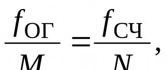
The basis of the frequency synthesizer is the PLL system. It is in the capture mode if the frequencies of the signals arriving at both PD inputs are equal, i.e. the condition

Where M And N are the division ratios of the frequency dividers Del1 and Del2.
By selecting the appropriate frequency channel number, the operator sets the division factor N divider with a variable division factor Del2. As a result, after the end of transients in the PLL loop, the frequency at the output of the VCO takes on the value
 .
.
In AM receive and transmit modes, only one slowly varying voltage is applied to the VCO from the PLL output. In the FM transmission mode, in addition to this voltage, which provides the desired carrier frequency with high stability, a second control voltage is applied to the VCO from the output of the baseband signal amplifier of the FM path (MC-FM). The spectrum of this voltage is limited to the band of a standard telephone channel 300–3400 Hz, and the level is set to provide the maximum value of the MF frequency deviation of 1.25 kHz.
An important role in the operation of the midrange is played by the LPF PLL. The cutoff frequency of this filter is approximately 5 Hz, which ensures good spectral purity of the signal at the output of the synthesizer. On the other hand, the cutoff frequency of the filter is significantly lower than the minimum value of the modulating frequency (300 Hz). In FM mode, this makes it possible to establish the desired nominal frequency value and the required long-term stability of the MF frequency while changing the instantaneous frequency of the VCO in accordance with the modulation law.
Buffer amplifiers BU1 and BU2 provide decoupling of the VCO from external influences and thereby increase the short-term frequency stability.
P2.3.3. transmission path
The MF signal from the output of the buffer stage BU2 enters the frequency doubler (UDV), in the collector circuit of which a two-loop bandpass filter with a bandwidth of approximately 25.5–30.3 MHz is included. Thus, a voltage with a frequency equal to twice the frequency of the MF is released at the output of the UDV. The deviation of the FM signal when passing through the UWT doubles and becomes equal to 2.5 kHz.
Further, the signal is amplified by two preliminary power amplifier stages (PA1 and PA2) with a low-Q resonant load and fed to a powerful output stage (PA3). At the output of UM3, the low-pass filters LPF Prd and LPF are turned on. The cutoff frequency of the filters is approximately 31 MHz, which provides the required attenuation of the side spectral components of the output signal (primarily carrier frequency harmonics), as well as matching the output impedance of the last stage transistor of the transmitter and antenna. The low-pass filter is common to the transmitter and receiver.
In the AM transmission mode, the signal from the microphone is fed to the modulating signal amplifier of the AM path (MU-AM). The MU-AM output provides sufficient modulating signal power required to implement collector modulation in the transmitter output stages. In the FM mode, UM2 and UM3 are supplied with a constant supply voltage.
P2.3.4. Receiving path
The radio receiving path is a superheterodyne receiver with double frequency conversion.
At the receiver input, a low-pass filter (LPF) is included with a cutoff frequency of about 31 MHz. The main purpose of this filter in the receive mode is to suppress interference with frequencies higher than the frequency of the received signal.
From the output of the low-pass filter, the signal goes to the diode limiter (Ogr), which serves to protect the transistor of the radio frequency amplifier (URCH) when the radio is in transmission mode. The adjustable attenuator (Att1) is an element of the receiver's AGC system: its attenuation increases when receiving strong signals. In addition, in the transmission mode, it, like the limiter, attenuates the transmitter signal at the input of the URF.
The band pass filter (BPF) has a bandwidth of 25.5–30.3 MHz. It provides the required attenuation of the receiver in the mirror and other side channels. In addition, a significant attenuation at frequencies above and below the operating range reduces the likelihood of non-linear effects in the URF due to the action of out-of-band interference (blocking, crosstalk and intermodulation).
Transistor URF determines the high sensitivity of the receiver. It is made according to the resonant amplifier circuit, which, on the one hand, allows you to obtain the necessary gain of the cascade, and on the other hand, provides additional attenuation through the side channels.
From the URF output, an amplified signal with a frequency f C is fed to the input of the 1st frequency converter (PrCh1). The signal of the 1st local oscillator with the frequency f G1. The resulting combination product with a difference frequency f WITH - f G1 is distinguished by a piezoceramic filter of lumped selectivity (FSI1), the center frequency of which is equal to the nominal value of the 1st IF ( f IF1 = 10.695 MHz) and the bandwidth is approximately 15 kHz. The selectivity of this filter is not sufficient to provide the required adjacent channel attenuation. It primarily serves to suppress interference on the image channel due to the second frequency conversion.
Attenuator Att2, like Att1, is an element of the AGC system.
Next, the signal is subjected to another frequency conversion in PrCh2. Its inputs receive signals with a frequency f FC1 and f G2. The frequency of the 2nd local oscillator (G2) is stabilized by a quartz resonator: f G2 = 10.24 MHz. The signal with the difference frequency formed in the PR2 f FC1 - f G2 is distinguished by the 2nd lumped selectivity filter (FSI2), the center frequency of which is equal to the nominal value of the 2nd IF (f IF2 =455 kHz), and the bandwidth is 10 kHz. The filter has a frequency response with good squareness and provides the required attenuation in the adjacent channel.
AD is made according to the classical diode scheme. BH - quadrature with FM to PM conversion and subsequent detection by a phase detector based on an analog multiplier.
The radio has a Silent Tuning System (SCN). It is used in FM mode, when strong noise is heard at the output of the receiver in the absence of a signal. Since the standby mode is usually much longer than the correspondent turns on, the noise at the output disturbs the operator.
The BSHN system passes the signal from the output of the preliminary UZCH to the volume control (Reg) and then to the output UZCH only when there is a useful signal at the BH output. The BSHN system consists of a noise signal amplifier (NW), a signal-to-noise analysis (AN) correlation circuit, and a key (BSHN Key). The operator can adjust the BSHN system response threshold up to its complete shutdown.
The receiver AGC system includes an amplitude detector (DAGC), a low-pass filter (LPF AGC) and two adjustable attenuators (Att1 and Att2).
P2.4. Schematic diagrams of the nodes of the radio station
The radio station is a rather complicated device. Therefore, the following is a description not of the complete circuit diagram of the radio station, but of its two parts: the input stages of the receiver and the nodes of the frequency synthesizer.
P2.4.1. Schematic diagram of the input stages of the receiver
On fig. P2.2 shows a circuit diagram of the receiver from the input of the Ogr limiter to the output of the Att2 attenuator (see Fig. P2.1).
The diode limiter is implemented on back-to-back diodes VD1 and VD2. When the input voltage exceeds 0.25–0.3 V, the diodes open and their resistance drops, which prevents a further increase in voltage.
The attenuator Att1 is made on a transistor VT2, which shunts the input when a positive control voltage is applied to it. U p from the AGC system (when receiving a strong signal) or from the controller chip (in transmission mode).
The PF bandpass filter is implemented on elements L2, L5–L7, L9, L11, C8, C9, C11–C13, C16, C17, C20–C22.
The radio frequency amplifier URC is made on a transistor VT1 according to a common base circuit. The load of the transistor is the resonant circuit formed by L4, C5-C7. Since the range of received frequencies is quite wide (25.615–30.105 MHz), the URF provides for the possibility of discrete tuning of the circuit by switched capacitors C6 and C7. The connection of these capacitors is made by transistor switches S1 and S2 according to the controller commands. Schematic diagrams of keys in fig. P2.2 are not shown.

Rice. P2.2. Schematic diagram of the input stages of the receiver
The frequency converter PrCh1 is made on field-effect transistors VT3 and VT4 according to a balanced circuit. The signal voltage is applied to the gates of the transistors, and the local oscillator to the sources. Diodes VD3 and VD4 reduce the level of combination components of higher orders in the drain circuit of transistors VT3 and VT4. At the output of PrCh1, a matching circuit L10, C19 and a piezoceramic filter of lumped selectivity FSI1 ZQ1 are included. Resistor R9 and transistor VT5 form an adjustable attenuator Att2.
P2.4.2. Schematic diagram of midrange nodes
On fig. P2.3 shows a schematic diagram of a voltage controlled oscillator (VCO), two buffer amplifiers (BU1 and BU2), as well as a PLL low-pass filter. The remaining nodes of the MF (FD, Del1, Del2, OG) are implemented on the integrated circuit of the controller.
The VCO is assembled on a VT3 transistor. The oscillatory circuit of the VCO is formed by the inductance L1, the capacitances of the varicaps VD1, VD2 and the capacitors C10–C13, C15, C16. In this case, capacitors C15, C16 form a capacitive divider that creates positive feedback and provides self-excitation of the generator. Capacitors C7, C8, C14 are separating, they do not affect the resonant frequency of the circuit.

Rice. P2.3. Schematic diagram of frequency synthesizer nodes
Switched capacitors C10-C13 are connected to the circuit using transistor switches S1-S4 on the commands of the controller. The need for these capacitors is due to the wide tuning ranges of the VCO (12.8075–19.41 MHz). Capacitors C10-C13 bring the natural frequency of the VCO closer to the currently generated frequency.
The VCO frequency, and hence the frequency at the midrange output, is set using the VD2 varicap. The control voltage is supplied to it from the output of the FD through a two-section low-pass filter PLL. The first link of the filter is formed by the resistor R1, the capacitance C1 and the input capacitance of the composite transistor VT1, VT2 connected in parallel to it, which, in turn, is increased by including the capacitance C3 in the collector-base circuit. The second link of the low-pass filter is formed by resistor R6 and capacitance C6.
Varicap VD1 provides a change in the VCO frequency in accordance with the modulation law when the transmitter is operating in FM mode. The required deviation value is set by potentiometer R5 at the factory setting of the radio.
The voltage generated by the VCO is taken from the emitter of the VT3 transistor and fed to two buffer amplifiers. BU1 is assembled on a transistor VT4, connected according to the scheme with a common emitter. From its output, the signal is fed to a divider with a variable division ratio Del2. Thus, the PLL loop is closed.
BU2 is implemented on the transistor VT5, connected according to the scheme with a common collector. From its output, the signal goes to the doubler of the UDV transmitter and the 1st frequency converter of the receiver PrCh1.
P2.5. Controls and controls of the radio station
The location of the controls and controls of the radio station "ALAN 78 PLUS" is shown in fig. P2.4.

Rice. P2.4. Controls of the radio station "ALAN 78 PLUS"
The numbers in Fig. P2.4 are marked:
1. CHANNEL switch. Frequency channel selection.
2. Multifunctional display with the following indicators:
frequency channel number and letter designation of the subband;
"SIG" - the level of the received signal in the receive mode or "PWR" - the power of the emitted signal in the transmit mode;
"AM / FM" - information about the work in the AM or FM mode;
“RX/TX” – information about operation in the receive (RX) or transmit (TX) mode;
"SCAN" - information about the operation in the scanning mode of frequency channels;
"EMG" - information about the work on the security channel.
3. EMG button - automatic tuning to the safety channel (9th channel of the main subband; frequency 27.065 MHz).
4 and 5. "Q.UP" and "Q.DOWN" buttons - hopping the tuning frequency by 10 channels up or down.
6. AM/FM button - select the type of modulation AM or FM.
7. Button "SCAN" - automatic scanning of the range. The receiver is tuned from channel to channel. Scanning stops when tuned to a working channel.
8. SQUELCH knob - adjusts the threshold of the silent tuning system.
9. “ON / OFF VOL” knob - combined volume control and radio switch.
10. "MIC" connector - a connector for connecting a microphone headset.
On the microphone headset there is a button for turning on the transmitter (tangent) and buttons for rebuilding to the next channel up and down in frequency (“UP” and “DOUN”).
On the rear panel of the radio station there are jacks for connecting an antenna (“ANTENNA”), an external speaker (“EXT”), an external level meter (“S.METER”), as well as a power connector.
The controls of the radio stations "ALAN 78 PLUS R" and "YOSAN" are somewhat different from the considered radio station "ALAN 78 PLUS".
The ALAN 78 PLUS R radio station does not have the EMG, SCAN, Q.UP and Q.DOWN buttons, but there is a DW (Dual Watch) button that provides the ability to control two reception channels at once (main and additional).
The radio station "YOSAN" has buttons "SCAN" and "DW". In addition, there is a "MO / RF" button that changes the mode of the level indicator. In the first position, the indicator shows the level of the modulating signal (the inscription “MOD” is displayed on the indicator), in the second - the level of the received or emitted radio signal (the inscription “SRF” is displayed on the indicator).
Radio station "YOSAN" can perform the functions of a megaphone. In this case, only the audio frequency amplifier of the radio station is used. To enter this mode, use the "PA" (Power Amplifier) switch, combined with the "SQUELCH" control. Megaphone mode only works when an external speaker is connected.